A Method Engineering Language for the Description of Systems Development Methods (Extended Abstract) Sjaak Brinkkemper1, Motoshi Saeki2, and Frank Harmsen3 1 Baan R&D, P.O. Box 143, 3770 AC Barneveld, Netherlands
[email protected] 2 Department of Computer Science, Tokyo Institute of Technology,
Ookayama 2-12-1, Meguro-Ku, Tokyo 152-8552, Japan
[email protected] 3 Cap Gemini Ernst & Young Management Consultants P.O. Box 3101, 3502 GC Utrecht, the Netherlands
[email protected]
Abstract. We propose a Method Engineering Language, called MEL, as a formal representation language for the description of method fragments, i.e. the development processes, and the products and deliverables of a systems development method. The language allows representing the structures of method fragments, the applicable consistency rules, and a variety of method assembly operators, all of which the semantics are formally defined. The MEL language is illustrated by a simple example of a Sequence Diagram of UML.
1
Introduction
Systems development methods have always been described in an informal and ad-hoc manner. Interpretation and application of these methods is therefore subject to personal and circumstantial factors. In order to reason or manipulate with methods in an unbiased, neutral way a universal language for the representation of methods and tools is required and some languages have been developed and applied [1] [5]. In this paper we will introduce a dedicated language for the description and manipulation of methods. We have called this language simply MEL: Method Engineering Language. In general, a specification language requires the expressive power to model the application domain in an effective manner, and should be practical to apply with respect to convenience, efficiency, and learnability [4]. For systems development methods in particular, the language should be able to support the representation and manipulation of 1) method fragments, i.e. method processes and method products, 2) development and project management aspects of methods, 3) conceptual definition and the supportive technical (i.e., tools) aspects of methods, and 4) constraints and rules concerning method fragments. MEL (Method Engineering Language), which we have developed, is intended to strike a balance between formal meta-modelling languages and graphical techniques used for method modelling. The language is able to represent in an integrated manner K.R. Dittrich, A. Geppert, M.C. Norrie (Eds.): CAiSE 2001, LNCS 2068, pp. 473–476, 2001. © Springer-Verlag Berlin Heidelberg 2001
474
Sjaak Brinkkemper, Motoshi Saeki, and Frank Harmsen
IS development methods both from the product perspective and the process perspective, as well as on various levels of decomposition and granularity. Moreover, MEL offers facilities to anchor method descriptions in an ontology, which is especially useful in the context of Situational Method Engineering. MEL provides operations to insert and remove fragments in and from the method base, to retrieve method fragments, and to assemble them into a situational method [2]. In the following sections the various constructs of MEL will be introduced.
2
Description Example in MEL
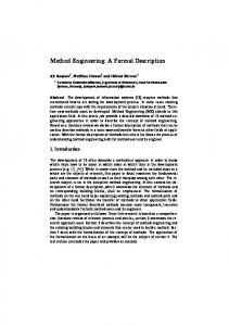
Methods and method fragments consist of product and process aspects. The product aspect specifies what products the developers should construct during a development process, while the process aspect navigates the developers to construct the products. The process descriptions suggest what activities and in what order are performed by the developers. Let's consider an example of the simplified version of Sequence diagram of UML [6, p. 3-97]. Figure 1 depicts the descriptions of the product of Sequence diagram and the process for constructing a Sequence Diagram. Figure 1-(a) shows the former meta-modelled in a Class Diagram of UML, while the latter in Figure 1 (b) is modelled in a Flow Chart.
Fig. 1. Method fragment of sequence diagram
As shown in Figure 1 (a), the objects that are in the system or in the external environments send and/or receive messages and the diagram depicts the timing of message passing, i.e. a chain of messages based on timing order. The association next denotes the timing order of the messages. To construct a Sequence Diagram, we begin with identifying objects. The second step is to pick up a scenario for achieving a function of the system. The scenario is refined and structured in the third step. The MEL description of the Sequence Diagram method fragment is given underneath. Descriptions that begin with the reserved word PRODUCT are product fragments. LAYER denotes the abstraction layer (granularity) of product fragments and, according to [4], there are four granularity levels defined: Concept, Diagram, Model, and Method. Association between concepts is enabled through ASSOCIATION, along with its cardinality and its roles. PART OF and IS_A specify aggregation and generalization relationships on method fragments respectively. We can express rules and constraints regarding method fragments with the RULE
A Method Engineering Language
475
construct, which does not appear in the example, as well as with the CARDINALITY property type. Rules are first order logic formulas and only address the static aspects of product fragments. As shown in the MEL specification, the process descriptions of method fragments are similar to those of conventional procedural programs. However, unlike to procedural programming languages, parallelism and non-determinism of development activities needs to be described. MEL has syntactic constructs to compose a complex process from activities, such as sequential execution, conditional branch, iteration, parallel execution and non-deterministic choice. In the example, the occurrences of hyphen ( - ) before activity names indicate sequential activities. Formally speaking, we have precedence relationship on activities specifying the execution order. Process fragments can be hierarchically decomposed into smaller ones in order to describe complex fragments in a comprehensive way. The construct PART OF relates a child process to a parent fragment in the hierarchical structure. The correlation of process and product fragments is established through the REQUIRED and DELIVERABLES section. PRODUCT Sequence Diagram: ID Sequence Diagram; IS_A Diagram; LAYER Diagram; SOURCE UML; PART OF Analysis Model, Dynamic Model; CREATED BY Construct a Sequence Diagram. PRODUCT Sequence Diagram: LAYER Diagram; PART OF Use Case Model; NAME TEXT; PRODUCT Object: LAYER Concept; PART OF Use Case Model; SYMBOL Rectangle; NAME TEXT; ASSOCIATED WITH {(send,), (receive,)}. PRODUCT Message: LAYER Concept; PART OF Use Case Model; SYMBOL Arrow; NAME TEXT; ASSOCIATED WITH {(send,), (receive,), (next,)}. ASSOCIATION send:
ASSOCIATES (Object, Message); CARDINALITY (1..1, 1..1). ASSOCIATION receive: ASSOCIATES (Object, Message); CARDINALITY (1..1,1..1). ASSOCIATION next: ASSOCIATES (Message, Message); CARDINALITY (0..1, 0..1). PROCESS Construct a Sequence Diagram: LAYER Diagram; TYPE Creation; PART OF Create an Analysis Model; REQUIRED {Interview results}; REQUIRED OPTIONAL Current Information system; ( - Identify Objects ; - Pick up a Scenario of a Function ; - Refine the Scenario as an interaction sequences ) DELIVERABLES {Sequence Diagram}.
476
3
Sjaak Brinkkemper, Motoshi Saeki, and Frank Harmsen
Operational Constructs of MEL
The MEL operations for situational method engineering and method adaptation are the following: 1. Insertion and maintenance of fragments of methods and tools in the method base by a methods administration function, e.g. inserting and removing method fragments to and from the method base; 2. Selection of the method fragments for the project based on a characterisation of the project from a method base; 3. Adaptation of method fragments to suit the aims of the method engineer, e.g. the operations for including a method fragment into another one; 4. Assembly of the selected method fragments into a situational method, e.g. the operations for assembling two product fragments into a new product fragment by specifying the association or associations through which they should be connected, and the operations for creating a precedence relationship between two process fragments or between a process fragment and a set of process fragments. Since the method assembly process is considered as a procedure consisting of a sequence of MEL operations, it can be described as a process fragment. A discussion and an extensive example of assembly operators can be found in [3].
4
Conclusion and Future Work
Departing from a set of requirements and purposes for method engineering languages, we have shown a part of MEL by using a simple example. It may be clear that the current textual format is not suitable as an end-user interface for a method engineer. Due to the complete formalisation of syntax and formal operational semantics of MEL [4], the language is unambiguous and suited to be serve as the underlying formalism for a Computer Aided Method Engineering (CAME) tool. This implementation has resulted in the MEL interpreter and editor contained in the Decamerone tool [3] environment for support of Situational Method Engineering.
References 1. 2. 3. 4. 5. 6.
Brinkkemper, S., and S.M.M. Joosten (Eds.), Method Engineering and Meta-Modelling. Special Issue. Information and Software Technology, vol. 38, nr. 2, pp. 259-305, 1996. Brinkkemper, S., M. Saeki, and F. Harmsen, Meta-Modelling Based Assembly Techniques for Situational Method Engineering. Information Systems, vol. 24, No. 3, pp. 209-228, 1999. Brinkkemper, S., M. Saeki, and F. Harmsen, A Method Engineering Language for the Description of Systems Development Methods. Baan R&D Report, November 2000. Harmsen, F., Situational Method Engineering, Moret Ernst & Young, 1997. Rolland, C., S. Nurcan, G. Grosz, A Decision Making Pattern for Guiding the Enterprise Knowledge Development Process. Journal of Information and Software Technology, Elsevier, 42(2000), p. 313-331. The Unified Modeling Language Specification Ver 1.3, http://www.rational.com, 1999.