Jan 18, 2007 - University of Colorado in partial fulfillment ...... downloading and installing new software. ... devices, (3) support novel methods for accessing the spectrum and (4) reduce the custom ...... FEC includes such techniques as linear block codes [34], cyclic ...... This equation can be used by a cognitive system to.
A Method for Dynamic Reconfiguration of a Cognitive Radio System by Troy Weingart B.S., Montana State University - Bozeman, 1991 M.S., University of Colorado - Boulder, 2000
A thesis submitted to the Faculty of the Graduate School of the University of Colorado in partial fulfillment of the requirements for the degree of Doctor of Philosophy Department of Computer Science 2006
Form Approved OMB No. 0704-0188
Report Documentation Page
Public reporting burden for the collection of information is estimated to average 1 hour per response, including the time for reviewing instructions, searching existing data sources, gathering and maintaining the data needed, and completing and reviewing the collection of information. Send comments regarding this burden estimate or any other aspect of this collection of information, including suggestions for reducing this burden, to Washington Headquarters Services, Directorate for Information Operations and Reports, 1215 Jefferson Davis Highway, Suite 1204, Arlington VA 22202-4302. Respondents should be aware that notwithstanding any other provision of law, no person shall be subject to a penalty for failing to comply with a collection of information if it does not display a currently valid OMB control number.
1. REPORT DATE
3. DATES COVERED 2. REPORT TYPE
18 JAN 2007
00-00-2007 to 00-00-2007
4. TITLE AND SUBTITLE
5a. CONTRACT NUMBER
A Method for Dynamic Reconfiguration of a Cognitive Radio System
5b. GRANT NUMBER 5c. PROGRAM ELEMENT NUMBER
6. AUTHOR(S)
5d. PROJECT NUMBER 5e. TASK NUMBER 5f. WORK UNIT NUMBER
7. PERFORMING ORGANIZATION NAME(S) AND ADDRESS(ES)
8. PERFORMING ORGANIZATION REPORT NUMBER
University of Colorado at Boulder,Boulder,CO,80309 9. SPONSORING/MONITORING AGENCY NAME(S) AND ADDRESS(ES)
10. SPONSOR/MONITOR’S ACRONYM(S) 11. SPONSOR/MONITOR’S REPORT NUMBER(S)
12. DISTRIBUTION/AVAILABILITY STATEMENT
Approved for public release; distribution unlimited 13. SUPPLEMENTARY NOTES
The original document contains color images. 14. ABSTRACT 15. SUBJECT TERMS 16. SECURITY CLASSIFICATION OF:
17. LIMITATION OF ABSTRACT
a. REPORT
b. ABSTRACT
c. THIS PAGE
unclassified
unclassified
unclassified
18. NUMBER OF PAGES
19a. NAME OF RESPONSIBLE PERSON
157
Standard Form 298 (Rev. 8-98) Prescribed by ANSI Std Z39-18
This thesis entitled: A Method for Dynamic Reconfiguration of a Cognitive Radio System written by Troy Weingart has been approved for the Department of Computer Science
Prof. Douglas C. Sicker
Prof. Dirk Grunwald
Prof. John Bennett
Prof. Tom Lookabaugh
Prof. Dale Hatfield
Date The final copy of this thesis has been examined by the signatories, and we find that both the content and the form meet acceptable presentation standards of scholarly work in the above mentioned discipline.
iii Weingart, Troy (Ph.D., Computer Science) A Method for Dynamic Reconfiguration of a Cognitive Radio System Thesis directed by Prof. Douglas C. Sicker
Advances in process technology, manufacturing, and architecture have ushered in an age of faster, smaller, and cheaper electronic devices. Emerging processor technology has made it possible to migrate applications that were traditionally implemented in custom silicon to general purpose processors. In the area of wireless communications, this transition has given birth to the field of cognitive and software-defined radio (C/SDR). These C/SDRs offer a broad range of opportunities for improving the use and utilization of radio frequency spectrum. This includes the creation of radio networks that can reconfigure their operation based on application requirements, policy updates, environmental conditions, and the ability to adapt to a wide range of protocols. One of the key benefits of having a C/SDR is its ability to change communication parameters in response to changes in application needs and/or changes in the radio frequency landscape. Such reconfiguration requires an understanding of how these communication parameters interact within the network protocol stack. Analysis of these parametric cross-layer interactions is a critical precursor in the development of a predictive model and algorithm for dynamic reconfiguration of a C/SDR. This work investigates how parameters at the physical, data link, network, and application layers interact, how desirable configurations of these parameters can be determined, and how these parameters affect the performance of file transfer and Voice over IP applications. An analysis of varying communication parameters across networking layers is used to inform the design, implementation, and evaluation of a predictive model and algorithm for dynamic reconfiguration of a cognitive radio. This model and algorithm allow a C/SDR to dynamically modify its configuration in order to improve
iv system performance. A systematic method for development of a cognitive platform is presented. This method uses statistical analysis of variance and design of experiments techniques to inform the design and implementation of a dynamic reconfiguration algorithm. This algorithm exploits cross-layer interactions to improve system performance, adapt to the needs of users, and respond to changes in the radio frequency environment.
“The views expressed in this article are those of the author and do not reflect the official policy or position of the United States Air Force, Department of Defense, or the U.S. Government.”
Dedication
This work is dedicated to my family. To my wife, the love of my life, faithful friend, and devoted mom; and to my kids, who were always cheerful and understanding when Dad was typing on the computer rather than reading to them or playing soccer in the park. It was a long and difficult journey for our family with the stress of the PhD and living apart from them for the better part of three years. I love you all very very much and couldn’t have made it without you. Finally, I would like to thank my parents for their love, support, and encouragement through the years (love you Mom and Dad).
vi
Acknowledgements
First and foremost I would like to thank my advisor, Doug Sicker, for his patience, tireless effort, outstanding guidance, understanding and friendship. I would also like to thank my co-advisor, Dirk Grunwald, for his thoughtful insight, willingness to offer feedback, and friendship. Finally,pysh I’d like to thank the members of the CU systems lab for their help in creating graphs, proofreading publications, and friendship over the years.
vii
Contents
Chapter 1 Introduction
1
1.1
Challenges in Cognitive/Software Radio . . . . . . . . . . . . . . . . . .
6
1.2
Research Focus . . . . . . . . . . . . . . . . . . . . . . . . . . . . . . . .
10
1.3
Major Contributions . . . . . . . . . . . . . . . . . . . . . . . . . . . . .
11
1.4
Overview . . . . . . . . . . . . . . . . . . . . . . . . . . . . . . . . . . .
13
2 Review of Literature 2.1
2.2
14
Software Defined Radio . . . . . . . . . . . . . . . . . . . . . . . . . . .
14
2.1.1
SPEAKeasy: Military Software Radio . . . . . . . . . . . . . . .
15
2.1.2
Joint Tactical Radio System . . . . . . . . . . . . . . . . . . . . .
16
2.1.3
Rapidly Deployable Radio Network . . . . . . . . . . . . . . . . .
17
2.1.4
Virtual Radios/VANU Inc. . . . . . . . . . . . . . . . . . . . . .
17
2.1.5
End to End Reconfiguratility (E2R) . . . . . . . . . . . . . . . .
18
2.1.6
SoftMAC and MultiMAC . . . . . . . . . . . . . . . . . . . . . .
18
2.1.7
Summary . . . . . . . . . . . . . . . . . . . . . . . . . . . . . . .
19
Cognitive Radio . . . . . . . . . . . . . . . . . . . . . . . . . . . . . . . .
20
2.2.1
Genesis Of Cognitive Radio . . . . . . . . . . . . . . . . . . . . .
21
2.2.2
DARPA neXt Generation Communications . . . . . . . . . . . .
22
2.2.3
Cognitive Radio Networks . . . . . . . . . . . . . . . . . . . . . .
24
viii
2.3
2.4
2.5
2.2.4
Algorithms for Cognitive Radio . . . . . . . . . . . . . . . . . . .
25
2.2.5
Summary . . . . . . . . . . . . . . . . . . . . . . . . . . . . . . .
27
Reliability Within a Network Protocol Layer . . . . . . . . . . . . . . .
28
2.3.1
Physical Layer . . . . . . . . . . . . . . . . . . . . . . . . . . . .
29
2.3.2
Data Link Layer . . . . . . . . . . . . . . . . . . . . . . . . . . .
30
2.3.3
Network Layer . . . . . . . . . . . . . . . . . . . . . . . . . . . .
31
2.3.4
Transport Layer . . . . . . . . . . . . . . . . . . . . . . . . . . .
31
2.3.5
Summary . . . . . . . . . . . . . . . . . . . . . . . . . . . . . . .
33
Dynamic Protocol Adaptation . . . . . . . . . . . . . . . . . . . . . . . .
33
2.4.1
Cross-layer Optimization . . . . . . . . . . . . . . . . . . . . . .
33
2.4.2
Flexible and Adaptive MAC Design . . . . . . . . . . . . . . . .
35
2.4.3
Summary . . . . . . . . . . . . . . . . . . . . . . . . . . . . . . .
37
Focus of Related Work . . . . . . . . . . . . . . . . . . . . . . . . . . . .
37
3 Method
39
3.1
Assumptions . . . . . . . . . . . . . . . . . . . . . . . . . . . . . . . . .
40
3.2
Problem Decomposition . . . . . . . . . . . . . . . . . . . . . . . . . . .
41
3.2.1
Component Framework . . . . . . . . . . . . . . . . . . . . . . .
41
3.2.2
An Abstraction for C/SDR . . . . . . . . . . . . . . . . . . . . .
44
Experimentation . . . . . . . . . . . . . . . . . . . . . . . . . . . . . . .
47
3.3.1
Layout and Setup . . . . . . . . . . . . . . . . . . . . . . . . . .
48
3.3.2
External Parameters and Environmental Variables . . . . . . . .
48
3.3.3
Internal Parameters . . . . . . . . . . . . . . . . . . . . . . . . .
49
3.3.4
Metrics . . . . . . . . . . . . . . . . . . . . . . . . . . . . . . . .
51
3.3.5
Analysis with Average Effect of a Parameter . . . . . . . . . . .
52
3.3.6
Analysis with Design of Experiments . . . . . . . . . . . . . . . .
53
Algorithm Development . . . . . . . . . . . . . . . . . . . . . . . . . . .
59
3.3
3.4
ix
3.5
3.4.1
Algorithm Decomposition . . . . . . . . . . . . . . . . . . . . . .
59
3.4.2
Metrics for Algorithm Evaluation . . . . . . . . . . . . . . . . . .
64
Experimental Platform - Simulation in OPNET . . . . . . . . . . . . . .
65
3.5.1
Setup and Layout . . . . . . . . . . . . . . . . . . . . . . . . . .
65
3.5.2
Limitations of the Simulation Platform
. . . . . . . . . . . . . .
66
3.5.3
Custom Simulation Model . . . . . . . . . . . . . . . . . . . . . .
67
4 Simulation Results and Findings 4.1
4.2
71
Experimental Analysis . . . . . . . . . . . . . . . . . . . . . . . . . . . .
71
4.1.1
Average Effect of Parameter . . . . . . . . . . . . . . . . . . . . .
72
4.1.2
Analysis of Variance . . . . . . . . . . . . . . . . . . . . . . . . .
88
4.1.3
Impact of a Parameter and Multi-Factor Analysis . . . . . . . . . 109
4.1.4
Experimental Analysis - Summary of Findings . . . . . . . . . . 121
Algorithm Performance . . . . . . . . . . . . . . . . . . . . . . . . . . . 122 4.2.1
Comparative Performance . . . . . . . . . . . . . . . . . . . . . . 123
4.2.2
General Performance . . . . . . . . . . . . . . . . . . . . . . . . . 132
4.2.3
Algorithm - Summary of Findings . . . . . . . . . . . . . . . . . 133
5 Conclusion
134
5.1
Contributions . . . . . . . . . . . . . . . . . . . . . . . . . . . . . . . . . 134
5.2
Findings . . . . . . . . . . . . . . . . . . . . . . . . . . . . . . . . . . . . 135
5.3
Future Work . . . . . . . . . . . . . . . . . . . . . . . . . . . . . . . . . 135
Bibliography
137
x
Tables
Table 1.1
Radio Taxonomy . . . . . . . . . . . . . . . . . . . . . . . . . . . . . . .
2
3.1
External Parameters and Environmental Variables . . . . . . . . . . . .
49
3.2
Internal Parameters . . . . . . . . . . . . . . . . . . . . . . . . . . . . .
50
3.3
Metrics . . . . . . . . . . . . . . . . . . . . . . . . . . . . . . . . . . . .
52
3.4
Factors and Responses for 802.11 Wireless Test Example . . . . . . . . .
56
3.5
Results from 802.11 Wireless Test Example . . . . . . . . . . . . . . . .
57
3.6
ANOVA for Latency . . . . . . . . . . . . . . . . . . . . . . . . . . . . .
58
3.7
Reconfiguration Metrics . . . . . . . . . . . . . . . . . . . . . . . . . . .
65
4.1
Internal Parameters . . . . . . . . . . . . . . . . . . . . . . . . . . . . .
72
4.2
External Parameters and Environmental Variables . . . . . . . . . . . .
72
4.3
Metrics . . . . . . . . . . . . . . . . . . . . . . . . . . . . . . . . . . . .
72
4.4
Perspectives on Performance Metrics . . . . . . . . . . . . . . . . . . . .
73
4.5
ANOVA for HL Throughput . . . . . . . . . . . . . . . . . . . . . . . . .
89
4.6
ANOVA for FTP Throughput . . . . . . . . . . . . . . . . . . . . . . . .
90
4.7
ANOVA for VoIP Throughput
. . . . . . . . . . . . . . . . . . . . . . .
91
4.8
ANOVA for RMAC Throughput . . . . . . . . . . . . . . . . . . . . . .
92
4.9
ANOVA for HL Bit Loss . . . . . . . . . . . . . . . . . . . . . . . . . . .
94
4.10 ANOVA for FTP Bit Loss . . . . . . . . . . . . . . . . . . . . . . . . . .
95
xi 4.11 ANOVA for VoIP Bit Loss . . . . . . . . . . . . . . . . . . . . . . . . . .
96
4.12 ANOVA for RMAC Bit Loss
. . . . . . . . . . . . . . . . . . . . . . . .
97
4.13 ANOVA for HL Latency . . . . . . . . . . . . . . . . . . . . . . . . . . .
99
4.14 ANOVA for FTP Latency . . . . . . . . . . . . . . . . . . . . . . . . . . 100 4.15 ANOVA for VoIP Latency . . . . . . . . . . . . . . . . . . . . . . . . . . 101 4.16 ANOVA for RMAC Latency . . . . . . . . . . . . . . . . . . . . . . . . . 102 4.17 ANOVA for HL Jitter . . . . . . . . . . . . . . . . . . . . . . . . . . . . 104 4.18 ANOVA for FTP Jitter . . . . . . . . . . . . . . . . . . . . . . . . . . . 105 4.19 ANOVA for VoIP Jitter . . . . . . . . . . . . . . . . . . . . . . . . . . . 106 4.20 ANOVA for RMAC Jitter . . . . . . . . . . . . . . . . . . . . . . . . . . 107 4.21 Top Three Factors Influencing Response . . . . . . . . . . . . . . . . . . 109 4.22 Top Three Factors Influencing Response and Their Effect . . . . . . . . 120 4.23 Best and Worst Case Static Configurations . . . . . . . . . . . . . . . . 123
xii
Figures
Figure 1.1
European Spectrum . . . . . . . . . . . . . . . . . . . . . . . . . . . . .
5
1.2
Challenges in Cognitive Radio . . . . . . . . . . . . . . . . . . . . . . . .
11
2.1
Development Timeline . . . . . . . . . . . . . . . . . . . . . . . . . . . .
15
2.2
DARPA XG Architecture . . . . . . . . . . . . . . . . . . . . . . . . . .
23
3.1
Research Method . . . . . . . . . . . . . . . . . . . . . . . . . . . . . . .
40
3.2
Component Framework . . . . . . . . . . . . . . . . . . . . . . . . . . .
43
3.3
Adverbs for C/SDR . . . . . . . . . . . . . . . . . . . . . . . . . . . . .
46
3.4
Experimental Process . . . . . . . . . . . . . . . . . . . . . . . . . . . .
47
3.5
Experimental Layout . . . . . . . . . . . . . . . . . . . . . . . . . . . . .
48
3.6
Average Effect on VoIP Latency . . . . . . . . . . . . . . . . . . . . . .
53
3.7
Prediction Cycle . . . . . . . . . . . . . . . . . . . . . . . . . . . . . . .
54
3.8
Components of the Cognitive Algorithm . . . . . . . . . . . . . . . . . .
60
3.9
Message Exchange for Reconfiguration Cycle . . . . . . . . . . . . . . .
62
3.10 Configuration Selection Process . . . . . . . . . . . . . . . . . . . . . . .
64
3.11 Simulation Layout . . . . . . . . . . . . . . . . . . . . . . . . . . . . . .
66
3.12 Node Model . . . . . . . . . . . . . . . . . . . . . . . . . . . . . . . . . .
68
3.13 Cognitive Process . . . . . . . . . . . . . . . . . . . . . . . . . . . . . . .
69
3.14 Media Access Control Layer . . . . . . . . . . . . . . . . . . . . . . . . .
70
xiii 4.1
Average Effect of a Parameter on HL Throughput . . . . . . . . . . . .
75
4.2
Average Effect of a Parameter on FTP Throughput
. . . . . . . . . . .
75
4.3
Average Effect of a Parameter on VoIP Throughput . . . . . . . . . . .
76
4.4
Average Effect of a Parameter on RMAC Throughput . . . . . . . . . .
76
4.5
Average Effect of a Parameter on HL Bit Loss
. . . . . . . . . . . . . .
78
4.6
Average Effect of a Parameter on FTP Bit Loss . . . . . . . . . . . . . .
78
4.7
Average Effect of a Parameter on VoIP Bit Loss . . . . . . . . . . . . .
79
4.8
Average Effect of a Parameter on RMAC Bit Loss . . . . . . . . . . . .
79
4.9
Average Effect of a Parameter on HL Latency . . . . . . . . . . . . . . .
81
4.10 Average Effect of a Parameter on FTP Latency . . . . . . . . . . . . . .
81
4.11 Average Effect of a Parameter on VoIP Latency . . . . . . . . . . . . . .
82
4.12 Average Effect of a Parameter on RMAC Latency . . . . . . . . . . . .
82
4.13 Average Effect of a Parameter on HL Jitter . . . . . . . . . . . . . . . .
84
4.14 Average Effect of a Parameter on FTP Jitter . . . . . . . . . . . . . . .
84
4.15 Average Effect of a Parameter on VoIP Jitter . . . . . . . . . . . . . . .
85
4.16 Average Effect of a Parameter on RMAC Jitter . . . . . . . . . . . . . .
85
4.17 Interaction of Data Rate and FEC on Throughput . . . . . . . . . . . . 111 4.18 Interaction of Data Rate and ARQ on Throughput . . . . . . . . . . . . 112 4.19 Interaction of FEC and ARQ on Throughput . . . . . . . . . . . . . . . 113 4.20 Interaction of FEC and ARQ on Bit Loss . . . . . . . . . . . . . . . . . 114 4.21 Interaction of FEC and xmitPower on Bit Loss . . . . . . . . . . . . . . 115 4.22 Interaction of ARQ and xmitPower on Bit Loss . . . . . . . . . . . . . . 116 4.23 Interaction of Data Rate and FEC on Latency . . . . . . . . . . . . . . 117 4.24 Interaction of Data Rate and ARQ on Latency . . . . . . . . . . . . . . 118 4.25 Interaction of FEC and ARQ on Latency . . . . . . . . . . . . . . . . . 119 4.26 Interaction of Data Rate and FrameSize on Jitter . . . . . . . . . . . . . 120 4.27 Reconfiguration Algorithm . . . . . . . . . . . . . . . . . . . . . . . . . . 122
xiv 4.28 MCC vs. Best and Worst Static Configurations on Throughput . . . . . 124 4.29 MCC vs. Best and Worst Static Configurations on Bit Loss . . . . . . . 126 4.30 MCC vs. Best and Worst Static Configurations on Latency . . . . . . . 127 4.31 MCC vs. Best and Worst Static Configurations on Jitter . . . . . . . . . 128 4.32 Radio Frequency Propagation for MCC vs Best Configuration . . . . . . 129 4.33 MCC vs. Best and Worst Static Configurations - Average Throughput . 130 4.34 MCC vs. Best and Worst Static Configurations - Average Bit Loss . . . 130 4.35 MCC vs. Best and Worst Static Configurations - Average Latency . . . 131 4.36 MCC vs. Best and Worst Static Configurations - Average Jitter . . . . . 131 4.37 MCC vs. Best and Worst Static Configurations - Average Power Output 132 4.38 Time to Reconfigure . . . . . . . . . . . . . . . . . . . . . . . . . . . . . 133
Chapter 1
Introduction
A convergence of technology trends is changing the operational and design characteristics of radio devices. The first of these technology trends is software-defined radio (SDR). SDRs allow much of what was previously done with application specific hardware, such as signal processing, to be accomplished in software. The ideal software radio is one that allows all signal processing, with exception of the analog antenna, to be done digitally [14]. Next are frequency agile devices, systems that can change how and where they operate within the radio spectrum, moving among a set of frequency bands in response to interference or other constraints. Finally, there is cognitive radio (CR), wherein the device can autonomously make decisions about its operation, in response to environmental changes, such as interference. Such capabilities enable SDRs to vary waveforms and frequencies within their hardware constraints, as well as change how their network protocols operate. One analogy that has worked well when discussing C/SDR stems from the way in which traditional analog radio devices were operated. These older devices required the turning of a knob to change frequency or the flipping of switches to enable features. A cognitive engine running on a software-radio would dynamically “turn” and/or “flip” these virtual knobs and switches to affect the radio. While this analogy breaks down in its oversimplification of the problem, some may find it useful.
2 A SDR can be described as a transceiver in which much of the physical layer is programmable, allowing the device to be reconfigured to meet changing needs or changes in the radio frequency (RF) environment. Key to this ability to reconfigure is support for different modulation schemes, frequency adaptation, and portable waveforms. The International Telecommunications Union Radiocommunications (ITU-R) defines an SDR as, “A radio in which the RF operating parameters of frequency range, modulation type, and/or output power can be set or altered by software, or the technique by which this is achieved [40].” Higher up the network protocol stack we have the ability to adapt the media access control and routing capabilities, although this higher layer functionality is generally not considered part of an SDR. The foundations of SDR are rooted in a collection of hardware and software whose objective is to move as much of the radios processing from the analog to the digital domain and from the hardware to the software domain, thus affording the flexibility, interoperability, and efficiency required [14]. Table 1.1: A Taxonomy of Traditional, Software-Defined and Cognitive Radios Radio Type Traditional
Software Defined
Cognitive
Characteristics Specific functionalities determined during initial design Design based on non-adaptive models Implemented in hardware, e.g., ASIC-based technology Limited upgradeability New functionality can be added through software updates Design largely based on software design models Implemented on general purpose processors, relies on software Enhanced upgradeability Required functionality can be determined and negotiated Combines software design and reasoning techniques Implemented in flexible hardware and/or software Intelligent upgradeability
3 In 1999, Mitola coined the term cognitive radio (CR), classifying a CR as a device that is aware of its environment and can adapt its operation in complex manners [39]. At its core, a CR can sense, adapt and learn from its surroundings. Together, cognitive and software-defined radio (C/SDR) can combine into a flexible and aware device. This combination allows for the creation of frequency agile radios, in which the device can autonomously select operating parameters in a way that improves spectrum utilization (referred to as dynamic spectrum utilization). One can envision an advanced wireless network that dynamically assigns spectrum or reconfigures in response to changes in policy and environmental conditions. Flexible spectrum usage raises interesting issues regarding the role of primary and secondary users. For example, to what extent is a secondary user allowed to interfere with a primary user? This level of flexibility in a wireless platform not only allows one to tackle the problem of spectrum utilization, but also offers the ability for devices to cooperatively configure themselves to support application quality of service demands in a networked environment. Table 1.1 provides a summary of the different classes of radios and their characteristics. C/SDRs have a broad range of capabilities and designs. At one end of this continuum are radios that incorporate computational intelligence. These radios require algorithms that sense, learn and act in response to changes in their environment [39]. The ultimate cognitive radio will be able to autonomously negotiate and propose entirely new communication protocols for use in a networked environment. In other words, this technology would allow devices to dynamically reconfigure their operational parameters to enhance performance metrics such as throughput, bit error rate and/or delay. At the other end of this continuum are devices that are functionally equivalent to their analog predecessors, although the newer wireless devices functionality has been implemented on field programmable gate arrays (FPGA), digital signal processors (DSP) and/or general-purpose processors (GPP).
4 One might appropriately ask whether frequency agile SDRs represent anything new. In some ways they do not. There are many systems and devices that incorporate some subset of C/SDR technology. For example, second generation cellular technology incorporates sophisticated transmit power control. Even typical 802.11 cards support many of the characteristics that we are seeking - they rely heavily on software to operate (although not at the physical layer); they can sense their environment (through listen-before-talk and channel sounding); and they can alter their frequency parameters (within a set of channels). However, they do all of these things in a rather rudimentary manner. One could also argue that even conventional hardware radios have some of these characteristics; however, they are much more limited in terms of their ability to dynamically alter their operation and they have certain physical limits in terms of reconfigurability (due to the constraints of adding additional hardware to support additional features). The configurations of such conventional devices are generally set during the design phase and there is little to no ability to alter this configuration post development, whereas SDRs overlay a software architecture on top of this model. This ability to alter the workings of the device post-production is powerful, in that it offers the ability to upgrade and/or patch a device that has already been deployed. Three well known motivations for instantiating C/SDRs are (1) for purposes of efficiently accessing spectrum, which is perceived as a scarce resource and (2) for improving interoperability of wireless devices, and (3) improving economies of scale in manufacturing. In the US and abroad, numerous government agencies (e.g., the Federal Communications Commission (FCC), the National Science Foundation (NSF), the Defense Advanced Research Projects Agency (DARPA), and the European End-toEnd Reconfigurability Project (E2R)), have realized that current radio technology will not adequately meet the demands of the future. Driving a shift in both research and funding is a desire for increased efficiency in our use of the available radio frequency spectrum. A recent study done in the Atlanta
5
Figure 1.1: Mid-high Band Spectrum Sample from a Large City in Europe, 1,200 MHz to 2,200 MHz (This graph is courtesy of Patrick Ryan)
metropolitan area reported that less than 7% of the available spectrum was being utilized during the several months that the study was conducted. Additionally, 77% of the spectrum in this area was completely unused [64]. However, observed availability does not mean that the spectrum is not “owned” by some agency or corporate body. The scarcity of spectrum is influenced by both technical and regulatory practices. However, “ownership” issues aside, it is clear that there is a vast amount of unused and underutilized spectrum. Figure 1.1 presents a graph of spectrum occupancy from 1.2 GHz to 2.2 GHz in a large European city (note the low occupancy in the band with the exception of the UMTS and GMS services). In addition to efficient spectrum use, there has also been a large amount of funding directed at solving interoperability problems encountered between military components and our allies during the conflicts in the Middle East. Domestically, we saw similar interoperability problems between public safety agencies responding to the 9/11 attacks. The ineffective use of the emergency bands during these terror attacks has given impetus
6 to many of the scenarios that illustrate the promise of C/SDR. A government agency could enact a change to local spectrum policy in response to a disaster. These updates to policy, when acted upon by an C/SDR, would reallocate spectrum to support increased demand during the emergency. C/SDR also promises to change the way radio and equipment updates are done. A C/SDR platform could adapt to new standards by downloading and installing new software. A C/SDR could reduce the cost to upgrade system software through remote system updates and upgrades. There are significant economic benefits to be had if one can intelligently exploit the highly flexible and reconfigurable nature of SDR platforms. Developers of wireless hardware can rely on the reconfigurable design of an SDR to decrease the costs associated with upgrading custom hardware (such changes can result in fabrication costs that significantly exceed US $1 million).
1.1
Challenges in Cognitive/Software Radio Challenges in C/SDR are loosely divided into two categories, those dealing with
policy or regulatory concerns and those dealing with technical problems. Often researchers’ interests are consumed by seemingly larger technical issues, when in reality these issues are confounded by policy and regulatory roadblocks. In order to understand the regulatory and policy issues one must understand the key desires of the regulator, primary spectrum user, and their opinion of the fundamental technical issues driving policy. The ability of frequency agile radios to sense radio frequencies and alter operational parameters such as frequency, power, modulation, beam direction and link access protocol creates an opportunity whereby devices could autonomously decide how best to operate to improve their access to the radio frequency environment. However, assessing the radio environment is a difficult task, one that may require the development of new hardware and software, complex propagation assessment techniques and information
7 integration. It also will require the radio community to rethink what defines harmful interference. New certification and assurance techniques will have to be developed in order to assure that frequency agile devices will not misbehave. To understand the need for certification, consider the problems that might arise if secondary user devices interfere with public safety and aeronautical users. The hope is that such adaptive devices will (1) allow for open radio architectures, (2) take advantage of price declines in computing devices, (3) support novel methods for accessing the spectrum and (4) reduce the custom nature of radio chip design. However, it is uncertain whether these devices might intentionally or inadvertently operate outside of their expected RF parameters. Regulators and incumbents must be comfortable with C/SDR technology before they will allow it to operate. Likely this will involve certification of the algorithms and mechanisms that drive the SDR. For incumbent RF license holders, certification gives assurance that the CR will not interfere in their transmission, and that the CR operating in their RF space will relinquish spectrum when required. There is also a large effort at reworking the current command-and-control model of spectrum allotment, assignment and allocation in the FCC. A transition to a legal structure that is more suited to advancements in radio technology, such as C/SDR and ultra-wideband, is underway. Various national regulatory agencies are working on improving spectrum policy, notably the Office of Communications (Ofcom) in the UK, the Ministry of Internal Affairs and Communications (MIC) in Japan and the FCC in the US. Ofcom recently released an in depth analysis of C/SDRs and has been active in promoting novel approaches to spectrum management [88]. In the US, the FCC is actively seeking to improve the efficiency of spectrum management and therein considering new regulatory models. These include (1) the development of secondary markets for spectrum, (2) the specification of receiver standards, (3) the consideration of C/SDRs, (4) exemptions for operation in TV bands and (5) the development of an interference temperature [19, 20, 21]. This regulatory interest represents a fundamental shift in thinking,
8 and is a key indicator that devices that use spectrum in new and exciting ways are in development. The significance of this type of regulatory reform must also be considered in the context of how regulatory agencies typically evolve. The potential for this new technology is quite substantial. However, this potential could be lost or delayed if the regulators find that the technology is not up to supporting new spectrum models. One concern for policy makers is whether interference can be avoided, and whether the device will operate as it should. The potential to interfere with primary spectrum users must be considered, particularly since these incumbent spectrum holders have substantial lobbying influence. Furthermore, current international treaties and laws do not consider spectrum sharing. Regulatory and policy issues notwithstanding, there are also a host of daunting technical problems to overcome. While not the focus of this thesis, there are also many interesting problems at the physical layer to consider. Various physical layer advances are required to achieve highly flexible radios. One of the major challenges in creating a flexible SDR is that of developing a flexible RF front end. This challenge is being met through the ongoing development of Micro-Electro-Mechanical Systems (MEMS) based antenna [18]. Additionally, development of analog to digital converters that are appropriate for SDR systems requires changes to the sampling capability and the range of existing systems. Significant work is underway in the area of FPGA based SDRs [85]. Advances in these areas will have a significant impact on the realization of more flexible SDR platforms and therefore more flexible frequency agile radios. Many of the technical challenges in C/SDR are driven by Joe Mitola’s vision of the ultimate C/SDR [39]. He envisioned a system that was capable of reasoning about its environment. The system would draw upon past experience and current environmental conditions to make intelligent decisions about how it should reconfigure. Key components of realizing his vision are the radios ability to sense, remember, learn and act. In developing such technology, it will be important to understand how a C/SDR should
9 sense the environment, determine what environmental inputs should be processed and when, and also how it will communicate with other network devices. Additionally, it will be import to investigate how C/SDRs synchronize configurations, maintain communication during reconfiguration, and accomplish over-the-air software updates. Changes in the environment, goals, or networking conditions will force the radio to change its current operating mode, much in the way an operating system must respond to interrupts. One must understand how tradeoffs will be balanced by the C/SDR in meeting its goals. Additionally, it will be important to define and evaluate how the C/SDR is affected by interrupts to its current operating mode. The adaptive and dynamic natures of these systems lead to other interesting technical questions. It will be important to quantify the amount of time that a cognitive process can devote to computing a radio configuration, thus allowing characterization of the types of processing can be done without negatively affecting communication. Another challenge is devising a set of metrics that can be used to evaluate and guide the design of the computational engine. Additionally, there are numerous machine-learning problems that must be resolved before realizing the C/SDR vision. One must characterize what types of reconfiguration algorithms (case-based-reasoning, genetic algorithms, expert systems) are appropriate for networks of C/SDRs. These are but a few of many problems that must be overcome in distributed systems, security, and operating systems with respect to C/SDR. Possibilities abound for investigation into the utility of the SDR platform to capitalize on the benefits of cross-layer interaction and dynamic reconfiguration. A C/SDR could be used for research and experimentation with spatially aware applications, adaptive routing, cognitive media access control (MAC) layers, and mutable physical layers. The added flexibility and computational power afforded by a C/SDR has drawn manpower and money to their research and study.
10
1.2
Research Focus Frequency agility, or the ability of the radio to dynamically alter the frequency
it communicates over, is receiving a large amount of interest. The focus on frequency agility is driven by scarcity of the radio frequency resource and the potential for profit, provided one can uncover a way to improve use and utilization of that resource. Research in dynamic spectrum use is centered on ways to vacate or negotiate a clear communication band. However, there are situations in which a C/SDR cannot jump to an interference free channel to operate (i.e., the presence of military jammers, regulatory limitations, and/or scarcity of resources). This thesis focuses on what a C/SDR can accomplish to maximize its performance within a frequency band in the presence of interference. Specifically, the thesis of this work is: A C/SDR system that is experiencing active interference can improve performance by exploiting dynamic cross-layer parametric optimization. The scope of this work is limited to those problems faced by a C/SDR when dealing with a single jamming source, two stationary nodes, and a single communication link between them. In approaching this work, a decomposition of the problem lead to two interdependent areas of focus. For the first area, it followed that in order to develop a dynamic control algorithm for the C/SDR, one must first have a clear understanding of how the C/SDR’s settings affect its performance. For example, to optimize for throughput it is important to know the effect of tuning the radio to - bit rate (high), frame size (small), and transmit power (low). Once understanding the effects of the radio’s settings, one can move on to the second area of focus, the development of the algorithm. Informed design is the key principle in development of the cognitive engine. Chapter 3 will cover the details of this approach and discuss the techniques used for quantifying and analyzing the experimental results, and show how this drove the development of the algorithm.
11 Problem Improve wireless performance by Process expoiting cross-layer parametric interactions
Scope Vagueness of reliability Multi-dimensional complex problem Problem decomposition
Key Specification Metrics Performance Goals Literature Review Experimentation Development
Platform Development Simulation Soft/MultiMAC
Challenge Description Approach
Algorithm Development Global vs local min/max in search space Combine inputs to extend or develop new algorithms
Implementation C/SDR Integrate Adverbs Soft/MultiMAC Simulation Algorithms
Understanding Performace Intra/Inter layer Multi-dimensional Measurement Theory Literature Review Soft/MultiMAC
Figure 1.2: Challenges, Proposed Approaches, and Their Relationship to the Problem.
The scope of the challenges outlined in the previous section is enormous. However, when decomposed and focused by a directed thesis the tasks become more manageable. Figure 1.2 summarizes relevant challenges, the approach, and the relationship to this research. The following section will summarize the major contributions of this work.
1.3
Major Contributions The major contributions of this research are divided into three categories, 1) the
experimental parametric research, 2) the reconfiguration algorithm, and 3) the research platform. The first major contribution of this work is the presentation and analysis of the parametric interactions of the C/SDR platform. The experimental work makes use of Design of Experiments (DOE) and Analysis of Variance (ANOVA) to determine how a cognitive radio’s settings affect its performance. This analysis exhaustively examines
12 how each configuration of the C/SDR affects the performance of the system. The analysis includes single and multi-parameter interactions and effects. Additionally, a model for predicting a radio’s performance given its configuration is presented. The detailed results of the experimental investigation are reported in chapter 4. The second major contribution of the research is the design, implementation, and testing of an algorithm for dynamic reconfiguration of a cognitive system. The algorithm is based on achieving desired performance goals while maintaining the most conservative configuration (i.e., the configuration which meets requirements while maintaining minimum power output). The algorithm is discussed in detail in chapter 4. The final major contribution of this work was the development, testing, and evaluation of a platform for experimentation with C/SDR. The simulation platform developed in OPNET offers the researcher the ability to investigate how a C/SDR’s settings affect metrics of interest, validating the potential of this technique. The platform is flexible enough to allow communication parameters to be changed on a per-packet basis. Additionally, the platform allows for the development and comparison of algorithms for configuration of a C/SDR. This platform is discussed in detail in chapter 3. During the investigation of the thesis many related research questions were explored. Unavoidably, there were tradeoffs in achieving reliable communication and adequate performance over an actively jammed link. This work presents a method for balancing these tradeoffs. How a C/SDR is affected by changes to its current environment or operating mode revealed which changes required immediate, delayed, or no action. Quantifying the amount of time that a cognitive process devotes to computing a radio configurations is presented, thereby allowing characterization of the types of processing can be done without negatively affecting communication. A set of metrics was developed to evaluate and guide the design of the C/SDR’s computational engine. Finally, this work offers a method for specifying the requirements, goals, and limitations of the application or user requesting service from the network.
13
1.4
Overview The remainder of this document is organized as follows. The literature review
in chapter 2 describes prior work and contrasts this research with related academic and commercial work. This is followed in chapters 3 and 4 by a detailed look at the approach, platform, experimentation, and evaluation techniques that were undertaken, followed by detailed findings. Finally, this thesis concludes with a summary of the most significant results and a look at future work.
Chapter 2
Review of Literature
Cognitive and Software-Defined Radio (C/SDR) is a research area that is very broad in scope and could potentially benefit from a highly varied review of the literature. This chapter is focused primarily on methods and techniques, as described in prior work, that help achieve the focus of this thesis. Work that offers to improve performance through cross and intra-layer adaptation, interlayer adaptation, and methods for tuning the C/SDR is of particular interest. However, this chapter is purposefully broad in order to provide scope. The methods that will provide the most impact were targeted for use in the thesis of this work. Each of the following sections is devoted to an area of work directly related to this thesis. This includes a broad range of topics and aspects of SDR, CR and cross-layer and adaptive protocol design. Figure 2.1 provides a timeline of some of the major SDR developments.
2.1
Software Defined Radio This section provides a historical overview of software defined radios and intro-
duces two key components employed in this thesis. As described in the previous chapter, Mitola coined the term software defined radio while he was working at the Defense Advanced Research Projects Agency (DARPA). During the mid 1990s, DARPA and the Department of Defense (DOD) funded various projects crucial to the development of SDR. In recent years, academia and industry have taken the lead in advancing SDRs.
15 Software Defined Radio "Coined" 1991 Rapidly Deployable Radio Network 1994 Joint Tactical Radio System 1997 Cognitive Radio "Coined" 1999 DARPA neXt Generation 2001 Speakeasy 1992
1990
1991
1992
1993
Vanu Inc. GSM Basestation 2004
1994
1995
1996
1997
1998
1999
2000
2001
2002
2003
2004
2005
2006
2007
Figure 2.1: Timeline of Software-Defined and Cognitive Radio Developments
2.1.1
SPEAKeasy: Military Software Radio
SPEAKeasy was a joint program of the Air Force, Army, Navy, and DARPA that arose out of interoperability problems that were experienced during the Grenada conflict [48]. Rumor has it that Army troops called in air support using their personal calling cards. SPEAKeasy sought to develop a radio that would allow multiple waveforms at multiple frequencies to coexist in the same device and be compatible with legacy radios. Along with basic research and development, their production schedule included prototype demonstrations. The initial prototype, shown in 1995, demonstrated multi-band operation, programmability, and bridging. Development and prototype demonstrations continued until late in 1998. Some key ideas and concepts for software-defined radios arose during the development of this system. There was a need for a software architecture that would decouple the radio hardware from the software framework. This would allow hardware to advance independently of the software architecture. Additionally, they saw the need to capitalize on commercially available products, as the DOD could no longer afford to fund proprietary solutions. In order to ease maintenance of the radio, the developers saw a need for over-the-air updating of the radio software. SPEAKeasy was nominally one of the first software radios in operation. Many of the novel ideas and innovations that followed have roots in this program.
16 2.1.2
Joint Tactical Radio System
The Joint Tactical Radio System (JTRS) was founded on concepts that were part of the SPEAKeasy project and a vision document within the military (Joint Vision 2010/2020) [83]. This program is funding the production of a host of radios ranging from inexpensive terminals, with reduced waveform support, to multi-band/mode/channel radios that support advanced narrowband and wide-band capabilities. These high-end radios will also include integrated computer networking features. The primary goal of JTRS is to develop a family of radios that are able to meet expanding bandwidth requirements, are interoperable, affordable, and scaleable. The program managers felt that the only way to meet these objectives was to require that the radios conform to open physical and software architectures. JTRS has experienced significant difficulties in meeting program goals and cost constraints [15]. A key component of the JTRS is the Software Communications Architecture (SCA). The SCA is an open architecture framework that utilizes Common Object Request Broker Architecture (CORBA) to dictate the structure and operation of the radio. Critical components of the architecture are standards for loading waveforms, running applications and system integration. The SCA Hardware Framework (SCA/HW) dictates minimum specifications for hardware devices. These two frameworks assure software written to the SCA will work on compliant hardware. While this approach has some backing, there are numerous shortcomings. First, it has grown into a complex and heavy design. Second, it does not offer any capabilities for the emerging needs of a dynamic system such as a CR. Lastly, it is not well oriented toward lightweight implementations. The SCA is currently at version 3.0 and has been adopted as a standard by the Object Management Group (OMG). The current price tag on the development of the SCA has passed $1.3 billion and costs continue to increase. Additionally, the total production costs of individual components of the project are seeing drastic cost increases. The first
17 to be delivered, the cluster 1 vehicle mounted radios, have risen from $15.1 to $21.6 billion [15]. The cost increases were attributed to daunting technological challenges.
2.1.3
Rapidly Deployable Radio Network
The Rapidly Deployable Radio Network (RDRN) was another early SDR (19941999) that was specifically designed to address problems when implementing mobile, rapidly deployable, and adaptive wireless communications [72]. Researchers created a high-speed ATM-based wireless communication system that was adaptive at both the link and network layers, allowing rapid deployment and response in a changing environment. Their concept of operations was to deploy a backbone of switches that would auto configure into an appropriate topology enabling users to access the backbone via a cellular-like architecture. The RDRN project incorporated digitally controlled antenna beams, programmable radios, adaptive link layer protocols, and mobile node management. Their network layer routing protocol when linked with the directional phase array antenna was the basis for their adaptive point-to-point topology solution. Additionally, at the datalink layer they were able to change modulation, frame lengths, and enable and disable forward error correction. However, project literature states that these parameters are set when the radio is initially configured. They concede that the next step for the project would be to develop an algorithm that would run in the radio processor, enabling dynamic adjustments to power level, coding depth, antenna pointing, modulation type, and data rate.
2.1.4
Virtual Radios/VANU Inc.
Around 1995 there was a large amount of interest in the transition from specialized hardware to general-purpose processors (GPP) in the radio space. In his thesis, Vanu Bose set out to demonstrate that it was possible to implement a high-data rate, computationally intensive, real-time signal processing application on a GPP. This ef-
18 fort formed the basis of his thesis and later launched his company, Vanu Inc [14]. His doctoral work produced a software-radio that was able to run on a general-purpose processor. In this work he acknowledges that there would be significant opportunities to improve wireless networking using software radio technology. He recognized that a radio which could adapt and change its operating characteristics in real-time could significantly impact wireless communication. In November of 2004, Vanu’s software radio GSM base station became the first device to successfully complete the FCC’s certification process governing software radio devices [91]. Mid Tex Cellular operates the first commercial deployment of this system. Vanu’s Anywave GSM base station is capable of remote software updates, allows multiple standards to co-exist on one network, and has the potential to decrease cellular maintenance budgets by as much as 20% [97].
2.1.5
End to End Reconfiguratility (E2R)
The E2R project is one among a host of international efforts to realize the potential of C/SDR. The E2R project aspires to develop designs and prototype systems focusing on the end-to-end perspective. The project, now in its second phase, is focusing on producing platforms that are accessible across the device and user spectrum, ranging from advanced cellular handsets for the consumer to advanced spectrum management tools for the regulator [82].
2.1.6
SoftMAC and MultiMAC
SoftMAC is a software system developed at the University of Colorado by Neufeld et al [61]. This system was built to provide a flexible environment for experimenting with MAC protocols in the wireless domain. The ability to cheaply create, modify and conduct system level experimentation with hardware is often a goal of many research projects. However, many of these projects ultimately fail due to the cost, time, and effort involved in deploying a large scale experimental platform. The SoftMAC plat-
19 form fills this need. It uses a commodity 802.11b/g/a networking card with a chipset manufactured by the Atheros Corporation to build a software radio with predefined physical layers but a flexible MAC layer. Internally, the Atheros chipset provides considerable flexibility over the format of the transmitted packets, though this flexibility is not generally exposed by network drivers. By reverse-engineering many of those controls, SoftMAC provides a driver that allows extensive control over the MAC layer while still allowing use of the waveforms defined by the underlying 802.11b/g/a physical layers. MultiMAC, also developed at the University of Colorado, is intended to extend the basic SoftMAC environment to tackle problems in the areas of dynamic spectrum allocation and cognitive/software-defined radio [25]. It builds upon the functionality in the SoftMAC platform with some specific features in mind. First, MultiMAC allows multiple MAC layers to coexist in the network stack with minimal switching impact. Second, it allows one to dynamically reconfigure the MAC and physical layers on a per packet basis either from logic running as part of MultiMAC or from a user level process. Finally, by leveraging these capabilities MultiMAC allows intelligent reconfiguration of the MAC and physical layers, thus achieving a cognitive MAC. The cognitive MAC layer couples efficient reconfiguration afforded by MultiMAC with computational intelligence. This combination allows the engine to make smart decisions about which MAC layer should be used and which physical layer properties set.
2.1.7
Summary
This early research is important because of the progress made in the realization of the SDR. This research provides valuable insight into the design and implementation of future platforms. Additionally, the systems and research covered in this section give historical perspective and bolster the case for intelligent processing on a software radio. Much of this early work in SDR set the foundation for, and in some cases directly called
20 for research to begin in creating intelligent radio systems. Generally, the research and development in software-defined radio has been characterized by the building of systems to solve specific problems. The DoD efforts are focused on waveform portability and radio interoperability. The RDRN was centered on mobile and rapidly deployable disaster response communication. Vanu Bose’s work focused on solving problems associated with moving traditionally analog or custom ASIC components and processes to a general-purpose processor. Most of the problems in SDR lie in the development of more capable hardware and interoperable software frameworks. This base of adaptive protocol design has allowed for the development of the CU platforms, SoftMAC and MultMAC. Software radio research, although very active, has begun to give way to the recent popularity of cognitive radio.
2.2
Cognitive Radio Scientific and commercial interest in cognitive radio stems from its “lofty” goals:
to increase bandwidth, interoperability, and reliability through adaptive and efficient use of spectrum. In terms of spectrum policy (or the rules that govern spectrum usage), CR offers the ability to intelligently manage access to the spectrum. The popularity of CR in the research community is being fueled, in part, by this goal. Additionally, funding trends in DARPA and NSF have transitioned away from foundational SDR research to cognitive processes running on an SDR platform. It is easy to see that the funding trends and growth in interest are related, however, there have been few published works in the area. Early research has only just begun to tackle the issues raised when a system of these highly reconfigurable SDR platforms are acting in concert. Recall that the first commercially available software-radio platform was just recently made available in 2005. It follows that foundational work in C/SDR is often limited and focuses on the application of textbook techniques and simulations, rather than the genesis of entirely new algorithms.
21 2.2.1
Genesis Of Cognitive Radio
Joseph Mitola is credited with coining the phrase that is used to describe the joining of software-defined radio with computational intelligence, cognitive radio. He described how a cognitive radio could enhance the flexibility of personal wireless services through a new language called the Radio Knowledge Representation Language (RKRL) [39]. RKRL was a language for describing the features and capabilities of a radio. Mitola describes it as a set-theoretic ontology of radio knowledge. Mitola’s doctoral dissertation was presented in May of 2000. His research resulted in development of an architecture for CR and formulation of a set of use cases for computationally intelligent radios. Additionally, he developed a simulation environment in order to test the viability of RKRL. The focus of the simulation was centered on natural language processing. The experience he gained while conducting this simulation lead to the formulation of his architecture for CR. This work set the stage for research in the area of CR by providing enumeration of what it means for a radio to incorporate computational intelligence. He described 9 levels of operation that relate to the functionality of a cognitive device [39]. • Level 0 - Pre-programmed • Level 1 - Goal-driven • Level 2 - Context Awareness • Level 3 - Radio Aware • Level 4 - Capable of Planning • Level 5 - Conducts Negotiations • Level 6 - Learns Fluents • Level 7 - Adapts Plans • Level 8 - Adapts Protocols Indeed, DARPA’s Next Generation (XG) project is now developing radio systems that operate at level 5 (conducts negotiations) and academics are working on devices
22 that operate at level 7 (adapts plans). Mitola also described the possible steps that a CR might take in assessing its environment. These include observe, orient, plan, learn, decide and act. Various complex relationships might be defined among these steps. Mitola took a broad look at CR and the applicable algorithmic methods that could apply.
2.2.2
DARPA neXt Generation Communications
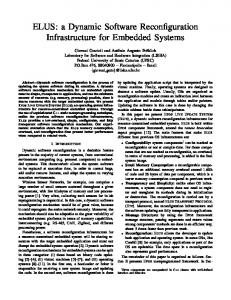
The Defense Advanced Research Projects Agency (DARPA) neXt Generation (XG) Communications Advanced Technology Office (ATO) is the project management arm of a DoD project whose objective is to develop and demonstrate a prototype spectrum agile radio [86]. They set a performance target of increasing spectrum utilization ten fold without causing harmful interference to non-cooperative radios. The project is addressing spectrum management difficulties associated with deployment and spectrum scarcity issues through development of devices and protocols for opportunistic spectrum access. In this scenario a primary user should not experience interference when a secondary user attempts to access a band. One method for mitigating inference by the secondary is to require the secondary to vacate the band and continually check for primary users. Much of the work in this area is dependent upon the development of highly sensitive detectors and the combination of individual and group sensing to determine the RF environment. Environmental data will be used to assist the device in making scheduling decisions about how best to operate. Other data could be derived from location, time of day, and databases containing pertinent data and policies on primary users. Web Ontology Language (OWL) will assist in the decision process by providing rules and behaviors in a machine-readable form. Together this information will allow the system to mark spectrum that is available for use. A secondary objective of the program was to leverage and develop technologies that enable dynamic access to spectrum within constraints provided by machine-
23 Policy Administrator
XG Prototype
Accreditation Boundary OWL Policy Database
Policy Conformance Reasoner
Policy Analyzer
Policy Manager
System Strategy Frequency Database Manager
Policy Enforcer
Scheduler
Accredited Kernel
Detectors
Tuner/Modem
Figure 2.2: The DARPA XG Architecture
readable policies. Technology central to this goal includes adaptive MAC protocols, hardware independent policy-based reasoning and new waveforms. The policy engine operates by obtaining a set of policy conditions that might associate with a certain device, in a certain location, attempting to make use of a certain band. The policies will be expressed in extensible markup language (XML) and the engine will parse these policies to determine a limited set of possible operational conditions for the device. The device then determines how these might best be used to meet communication requirements. Each of these policies is authenticated and its operation traceable. Ultimately, the goal is to provide a framework that describes the policy boundary for a device, and
24 allows the device flexibility to operate within these boundaries in a variety of ways. This system of policy driven operation is depicted in Figure 2.2. Additionally, XG is pursing the creation of a waveform that combines non-contiguous narrowband channels. These waveforms will respond to and capitalize on spectral vacancies in both time and frequency. Higher in the protocol stack the system is able to adapt to future MAC layer protocols and algorithms. Here the difficulty lies in being able to maximize spectrum utilization while still allowing short duration changes in the frequency used without saturating the network with protocol overhead. The XG project’s objectives are addressed through theoretical work, simulation and platform development.
2.2.3
Cognitive Radio Networks
Haykin provides a thorough overview of cognitive radio networks and describes the basic capabilities that a “smart” wireless device might offer [35]. Others describe techniques for applying CRs to improving the coordinated use of spectrum [10, 17]. Sahai et al., describes some of the physical layer limits and limitations of cognitive radios, including the difficulties associated with determining whether or not a radio frequency band is occupied [71]. Nishra has implemented a test bed for evaluating the physical and data link layers of such networks [62]. Additionally, Thomas describes the basic concept of a CR network and provides a case study to illustrate how such a network might operate [77]. It is also worth noting that the standards communities are focusing on cognitive radios. The IEEE 802.22 group is developing a wireless standard for the use of cognitive radios to utilize spectrum in geographically separated and vacant TV bands [23]. Also in the IEEE, the P.1900 workgroup is examining the general issue of spectrum management in next generation radio networks.
25 2.2.4
Algorithms for Cognitive Radio
This section details research in the area of applying intelligence to a software radio. The work ranges from somewhat simple techniques, including Listen Before Talk (LBT) and Dynamic Frequency Selection (DFS), to those more complex like game theory and genetic algorithms. Often the word “algorithm” causes one to envision a complex and involved solution to a problem. However, there are many algorithms that are simple, elegant and applicable to C/SDR. Algorithms of this sort are members of a class of direct methods for tackling problems associated with the design and implementation of a C/SDR. Some of the more well know approaches are the LBT algorithms, all variants on the notion that the sender should sense (listen) to the media before attempting to access it [36, 43, 54]. Another technique, transmit power control, seeks to minimize the transmit power used among nodes decreasing overall interference. Dynamic Frequency Selection (DFS) algorithms have seen a corresponding rise in interest coincident with the increase in popularity of C/SDR. Horne, details four common approaches: (1) Channel Availability Check - before starting a transmission the sender must monitor the channel for a defined period of time in order to determine whether a signal is present (e.g., LBT). (2) In-Service Monitoring - here the radio device must continually listen on the channel by searching for signals between transmissions. (3) Channel Abdication - upon detection of a signal the device must stop transmitting and move to another channel. And finally, (4) Channel Non-Occupancy - if a channel is occupied, the sending device will not utilize the channel for a set time period [36]. These techniques are present in common everyday devices like many cordless 900Mhz phones. These phones sense interference on a channel and switch to another in order to obtain a clear signal. Game theory relies on a mathematical model of an interactive decision process. Game theoretic research in C/SDR advocates an approach nearly opposite to that which
26 is advocated in this work; rather than using simulation or experimentation to inform the development of the algorithm the game theorist uses the analytical power of game theory to guide their algorithmic decisions. In [58, 59, 60], Neel et al. describe their use of this approach. The research cited is concerned about bounding and qualifying potential algorithms according to a “game” that approximates the function of a cognitive radio. The authors contend that game models will give insight into algorithmic complexity. This approach to bounding potential algorithms in a defined game space is helpful; however, it does not appear to offer direct insight into what the underlying algorithm should be. Other work in this area includes the application of machine learning or similar techniques to the problem of decision-making within cognitive radio networks. For example, Rieser describes a biologically inspired cognitive radio engine that employs genetic algorithms to optimize the robustness of the network [70]. He developed a cognitive model and architecture that was able to operate in unforeseen communication environments recalling past successful configurations via “memory”. Genetic algorithms are based upon the guided combination of “chromosomes”. In this case, a chromosome is a representation of a potential configuration of the radio system. His system would generate chromosomes and eventually settle on one that met the specified goal. System goals take the form of a weighted function, wherein numeric values are assigned to give importance to each variable. For example, to equally weight bit error rate and throughput one would give them the same value. The genetic algorithm was driven by a fitness function that was partially based on the weighted function. In genetic algorithms the fitness function is used to determine which chromosomes are passed on to successive generations of the algorithm, whereby the more fit chromosomes are combined in the hopes of forming more “fit” offspring at each successive generation.
27 2.2.5
Summary
Mitola’s visionary work established a common framework for research in cognitive radio. Mitola took a broad look at cognitive radio and the applicable algorithmic methods that one could apply. He also developed a description language (RKRL) for the radio that establishes a common basis upon which one could layer a heterogeneous cognitive process. A prototype system was not built to test his architecture and theories. A Java simulation of one of his use cases was developed and incorporated RKRL. This simulation was focused on natural language processing in the C/SDR domain and is not applicable to this work [39]. A broad range of potential algorithms exists for controlling CRs. LBT and DFS algorithms are important because they are simple algorithmic approaches that afford huge returns. Nevertheless, they suffer from one-dimensionality in that they solely focus on interference free channel access. Investigation of simple algorithms like LBT across multiple dimensions could yield promising results. A collection of simple algorithms acting in concert could drastically outperform individual component solutions. The game theoretic approach is useful if one is interested in characterizing potential algorithms in the “game space”, however, the algorithm behind this characterization remains a black box. The work presented here, informing the algorithm through experimental results, would only see minor benefit, if any, from a translation into the game theoretic space. The results from Rieser’s work in genetic algorithms indicates that a cognitive system can successfully reconfigure the radio in response to changing channel conditions, however, one critical piece of his work is not clear; the process of deriving the fitness function for his genetic algorithm. The fitness function used by Rieser was most likely based upon experimental results or was guided through informed design, thus lending support to the approach presented here. Beyond these described methods, numerous other techniques such as Markov models, neural nets, expert systems, and/or fuzzy logic
28 could be applied. However, the question remains as to which of these will be successfully applied in a fielded system (this thesis attempts to answer this question in part).
2.3
Reliability Within a Network Protocol Layer The intent of a communications network is to provide a means for the transport
of data. A fundamental requirement for such transport is to provide a certain level of reliability - one that maps to the needs of the supported communication. Reliable communications can be broadly defined as the ordered timely reception of data without unacceptable loss. Timely, as it is used here, refers to the applications requirements on data delivery. For example, streaming media applications have much different timing needs than an application that is doing a bulk transfer of email messages. The reliability of a system may be compromised as a result of buffering problems within the network device, due to software/hardware errors, timing problems, corruption of bits, and/or interference. Network reliability is commonly optimized through a variety of techniques at multiple levels of the protocol stack. The instantiation of reliability at the data link (i.e., HDLC) and transport layers (i.e., TCP - acknowledgments and resends) is common, but can also be implemented at the physical and network layers. Physical aspects of a network environment have significant impact on reliability. Attributes of the physical layer can be optimized to ensure low bit error rates. To counteract these differences, wireless protocol stacks rely on signal processing, media access control, and routing to improve overall reliability. When used in combination these techniques can improve the reliability of the network significantly. However, in practice, these measures are designed to operate within a layer and do so without any understanding of the environment or knowledge of the other layer’s capabilities. Signal reliability can be improved through adjustments to power, diversity and direction. Other techniques, including bit rate adaptation and custom signal processing,
29 can also be used to improve the reliability of a signal. At the data link layer, error detection, correction and flow control can all be used to improve reliability. At the networking layer, routing mechanisms can be applied to ensure reliable route connections - for example, flooding techniques can be applied to force multiple copies of a message across different network paths, with the hope that at least one will be successfully received. At the transport layer, there are numerous methods for improving reliability including, checksum techniques, timers, sequencing numbers, acknowledgments (both positive and negative) and windows. This following subsections provide a high level survey of reliability enhancing techniques with respect to the network protocol stack.
2.3.1
Physical Layer
Reliability of a network depends heavily on the type and characteristics of the physical media. Characteristics of optical networks are substantially different from those of wireless networks. Specifically, optical networks have bit error rates (BER) approaching 10−12 whereas radio networks can commonly experience bit error rates of 10−4 . In wireless networks, bit errors (and as a consequence packet loss) may be caused by attenuation, inter-symbol interference, doppler shift and multipath fading [5]. Furthermore, in wireless environments it is common to see bursty disturbances as opposed to the stochastic interference characteristics of wired systems. Radio networks must also be able to adjust to physical phenomena such as reflection, diffraction and scattering. Various techniques can be applied to the physical layer to improve reliable transport including power adjustment, changes in directionality, and encoding techniques. Several researchers have considered the role of directionality as a means of improving the performance of wireless systems [46, 100]. Moving from omni-directional to directional transmission allows for substantial spatial diversity improvements [66]. One technique for improving successful reception of a signal over distance is to increase signal power. However, increasing the signal comes with a price. You might (1) overwhelm the
30 receiver or neighboring nodes, (2) use more signal than is necessary, (3) violate the law (federal spectrum laws) and/or (4) consume unnecessary power (e.g., battery drain).
2.3.2
Data Link Layer
Various reliability mechanisms exist at the data link layer including link layer protocols, flow control, and error detection and correction. Early work in the area sought to design link layers for generally stable networks [38]. While in [3], Awerbuch et al., described algorithms to adapt to expressly unreliable links. A variety of link layer protocols can assist in improving the reliability of communications including, Automatic Repeat reQuest (ARQ), Channel Partitioning Protocols, Random Access Protocols and Turn Taking Protocols [50]. Each of these has their strengths and weaknesses. Certain types of reliable link layer protocols offer flow control. The basic idea is to throttle the sender until the receiver is ready to accept more frames. Both Stop-and-Wait and Sliding Window techniques can be used to prevent the sender from transmitting until the receiver provides permission [50]. Coding techniques can be used to improve the reliability of a received signal and to detect and/or correct errors. Error detection is commonly thought of in terms of parity checks, Cyclic Redundancy Checks (CRC) and other check-summing methods. Lin and Costello, provide a broad overview of basic error control coding techniques [50]. Techniques for one-way error correction are generally based on Forward Error Correction (FEC), which provides error-correcting codes that can automatically correct an error at the receiver. FEC includes such techniques as linear block codes [34], cyclic codes [65], BCH codes [69] and convolution codes [27]. These coding schemes differ substantially in their approach and application. Various researchers have focused on encoding in the wireless space. Work by Zorzi and Rau looks at probing ARQ techniques to lower retransmission in fading environments [101]. Other work by Ayanoglu et al. considered the asymmetric design of ARQ protocols where the complexity resides
31 in the base station [4]. It is well understood that link layer error recovery techniques are required to provide reliable data flows over wireless links. The reliance on transport layer recovery techniques results in poor throughput, loading problems, and inefficient use of the wireless link [26, 51, 52]. The length of the frame can have an impact on reliability. For example, a very large frame might be more efficient for large blocks of data, but if the frame is corrupted and a retransmission is required, the cost in overall channel efficiency can be significant. Various researchers have explored adaptive frame length as a mechanism for improving throughput and range [26, 49]. This work shows that adaptive frame length control can be exploited to improve throughput in the presence of noise.
2.3.3
Network Layer
The network layer allows packets to be routed through a network or internetwork to the proper destination. The goal of a routing protocol is to ensure that devices know what nodes to direct packets through to a destination. Huitema, provides a detailed survey of IP routing [37]. While most routing is based on the transmission of a packet along a single route to a destination, other techniques allow a packet to be replicated and flooded across numerous routes to ensure delivery. In [67], Ramanathan et al. provide an early survey of routing techniques for mobile environments. More recent work by Johnson [42] describes an early effort at mobile routing protocols for IP based networks. Also, in [66], Ramanathan examines the performance of ad hoc routing protocols for beam-forming antenna networks.
2.3.4
Transport Layer
In [30], Garlick et al. describe general problems and techniques for improving reliability at the transport layer. They discuss issues of flow control and sequencing in detail and provide general techniques for addressing these issues. A more recent treat-
32 ment of the subject includes discussion of adaptive bandwidth control and discussion of TCP in wireless environments [6, 16, 74]. A number of techniques exist at the transport layer to ensure reliability, including checksums, timers, sequencing numbers, ACK and windows. Checksums are often used at both the data link and transport layers. Checksums can include a broad range of methods from simple parity checks to complex cyclic redundancy checks [47]. Timers allow for a threshold to be set after which the assumption is that the transmission or acknowledgment failed. Sequence numbers allow for the accurate ordering of transmitted packets. In this scheme buffers hold packets while making requests for retransmission of erroneous or failed packets. Acknowledgements serve to inform the sender whether a packet has been received or a retransmit is required. Windowing allows for a negotiated increase or decrease in the number of packets sent over a period of time. This allows a receiver to throttle the sender while it processes packets [47]. Transport protocols such as TCP, while intended to be independent of the underlying network stack, were tailored to the operation of wired systems. Wireless networks differ from wired networks in significant ways. First, in wired networks lost Protocol Data Units (PDU) are typically a result of router discard due to congestion, whereas in wireless networks lost PDUs are typically a result of bit errors or handoff failures. Therefore, rather than apply congestion control (to minimize congestion at the router), a better technique is to detect the loss quickly and retransmit [7]. In addressing this difference, two solutions have emerged. One approaches the problem by suppressing congestion control [53] and the other tries to hide the problem by presenting a lower effective bandwidth (throttling at the link layer) [8]. A second difference between wired and wireless networks are the typical power and computational constraints. This has motivated the design of lightweight transport algorithms such as Mobile-TCP [33]. A more challenging consideration is to provide a transport protocol that operates well across both wired and wireless links, which represents an increasing percentage of net-
33 work traffic. This type of protocol will require algorithms that can adapt to changes in the network links as the transmission occurs, much as the work proposed here.
2.3.5
Summary
It is apparent from this survey of reliability techniques that there are a host of potential avenues to explore and consider in development of an experimental platform and algorithmic solution. The various techniques cited above were all considered in the design of cognitive engine presented as part of this work. The major difference between the work referenced here, and the solution presented, is the extension of reliability from an intra-layer process to one which spans layers. C/SDR provides a mechanism for exploring the effects of cross-layer reliability techniques. For example, you could have a directional antenna change routes to move traffic around a pocket of interference while turning on FEC and changing framesize. The experimental approach presented provides valuable insight into the potential of C/SDR to realize beneficial cross-layer effects.
2.4
Dynamic Protocol Adaptation This section describes efforts within the research community to improve system
performance through cross-layer adaption. This section also describes work on hybrid and flexible MAC design.
2.4.1
Cross-layer Optimization
Research in the area of cross-layer optimization in wireless systems has been an area of focus in recent years. Others have also spent a considerable amount time and effort investigating cognitive radios. However, the potential of improving the performance of a wireless system by combining cross-layer optimization with cognitive systems is just emerging as a research area. Since its inception, the layering principle, which segments
34 network functions and specifies standard interfaces between layers, has served the networking community well. There is a long research history of optimizing such functions within a layer, in a sense incremental-intra-layer optimization. This work includes such efforts as improved encoding techniques at the physical layer, novel media access techniques at the data link layer, adaptive routing design at the network layer, and enhancements to retransmit algorithms at the transport layer. However, various challenges, such as demand for bandwidth, the unsuitability of the standard TCP/IP protocol suite for wireless networks, the Internet commerce boom, etc. are driving researchers to look more closely at how the traditional networking layers interact and function. Much of the networking protocol research has been wire centric. The advent of wireless systems, with fundamentally different physical and data link layer characteristics, is pushing the need to rethink boundaries and the typical isolation of layers in traditional network protocol design. Work in the area of cross-layer optimization has typically focused on enhancing throughput, Quality of Service (QoS) and energy consumption [9, 31, 41]. However, these types of cross-layer optimizations tend to be limited in their application. In fact, most of the work in this area tends to focus narrowly on two layers, producing unique solutions. In other words, they do not incorporate a broadly adaptive solution nor do they consider user level requirements. Vadde et al. have applied response surface methodology and Design of Experiments (DOE) techniques to determine the factors that impact the performance of mobile ad hoc networks (MANETs) [78, 79, 80]. Their research considers routing protocols, QoS architectures, media access control (MAC) protocols, mobility models and offered load as input factors and throughput and latency as response factors. Their analysis demonstrates the usefulness of these techniques and shows where certain input factors can outperform others within a MANET.
35 Kawadia and Kumar present an interesting critique of cross-layer design in [45]. They warn that cross-layer optimization presents both advantages and dangers. The dangers they discuss include the potential for spaghetti design (in other words, complex seemingly unstructured design), proliferation problems and dependency issues.
2.4.2
Flexible and Adaptive MAC Design
MAC is a sublayer of the data link layer and the logical interface between the physical and link layers. The MAC is concerned with such things as link level addressing, frame limiting, error detection and control of the physical transmission [75]. Many of the more popular MAC protocols are defined by the IEEE 802 group [84]. In very simple terms, the MAC layer frames data and passes it to the physical layer. The task of arbitrating access to the physical medium is carried out through a variety of techniques embedded within the MAC layer. Commonly known algorithms for controlling access to the physical layer include Aloha, DQDB, CSMA/CD, CSMA/CA, and Token-ring. Some of these techniques are fairly simple, such as Aloha, wherein when frame arrives the MAC immediately forwards it to the physical layer for transmission. Other MACs like CSMA sense if the media is busy before transmitting. 802.11 defines a set of MAC specifications for wireless LANs. It provides coordination of access among clients and the base station by specifying a set of expected operations for access and reservation of the link. Primary 802.11 MAC functions include: scanning for channels, authentication and privacy, link control, access point association, RTS/CTS reservations, power control and packet fragmentation [1]. To gain access to the media, the standard defines two methods - distributed coordination function (DCF) and point coordination function (PCF). DCF is based on CSMA/CA and relies on a reservation timer (referred to as the Network Allocation Vector or NAV) to indicate when a transmitting client will be done. Clients must determine the time it will take to complete transmission and include this time in the duration header of the frame. DCF
36 also includes a random backoff timer to help prevent waiting clients from simultaneously starting transmission after the channel becomes available. Acknowledgments from the receiver allow the sender to know whether or not there was a collision. PCF on the other hand provides a polling technique, wherein the access point polls clients for their access requirements and assigns usage (providing support for synchronous data like video) [1]. Work on enhancements to wireless MACs is described in various papers. This prior research has shown that network efficiency can be increased by using multiple MAC layers simultaneously. Other work has shown that problems inherent in 802.11 networks can be improved upon by “overlaying” one MAC protocol on top of an existing protocol [68]. Finally, a variety of hybrid techniques and subtle variations on existing MACs have been proposed [28, 29, 56, 73, 32, 99, 57, 11, 12, 44, 55, 63]. Various hybrid MAC approaches are described in [73, 32, 99, 57, 11, 12, 44, 55, 63]. These approaches combine CSMA like bandwidth requests with scheduled allocation of bandwidth. That is, they incorporate the aspects of two separate types of MACs to form a composite MAC. Similar to these hybrid approaches there has also been work done in creating an overlay MAC layer (OML), which attempts to overcome the fairness and allocation problems inherent in the 802.11 MAC [68]. In [28, 29, 56], Farago et al. describe MetaMAC, a method for automatically selecting an optimal MAC protocol among a set of existing protocols. Their approach is to create an adaptive layer that sits on top of a set of existing MAC protocols. Rather than relying on a centralized controller to coordinate the selection process, MetaMAC makes use of a local feedback mechanism in selecting which MAC to apply to a packet. MultiMAC, described later, borrows from and extends this MetaMAC concept. An important initial difference between this work and MultiMAC is that MultiMAC is an actual implementation of an adaptive MAC layer. MultiMAC also provides flexibility in how and when the MACs are selected. For example, selection of a MAC could be driven by changes at the MAC layer (e.g., frame errors) or a user level process making requests for reliable transmission.
37 2.4.3
Summary
Hybrid MAC protocols are typically one-of-a-kind solutions. That is, a new “MAC” is created that embodies a set of requirements in order to attain a desired goal. Solutions of this nature must all interoperate at the MAC layer in order to function. As described later, the experimental platform used in this thesis exports an interface to the user level where the rules for deciding which MAC to use for transmitting a certain packet are viewable and editable. Unlike the MetaMAC and overlay MAC approaches, neither the number and selection of MACs nor the rules to choose between them are “hard-wired” into the system. This allows one to start with a set of criteria for the selection of a MAC layer. Depending on the context, one could also adapt and modify criteria using a case-based reasoning algorithm, thus transitioning to a cognitive platform. MetaMAC attempted to optimize the ability of a specific MAC protocol to access the media, only considering the success or failure of the access. This limits the range of possible MAC behaviors. For example, a MAC protocol that provides forward error correction with CSMA may be less successful at acquiring the media than a protocol with no error correction that uses oblivious access. On the other hand, in a noisy environment, the protocol with error correction would actually accomplish more. The complication in this example is that stations can only estimate the “useful work” or “yield” of packets they receive, unless the channel conditions are symmetric, some additional protocol may be needed to communicate this end-to-end information.
2.5
Focus of Related Work There is a large amount of prior work and active research that can be brought to
bear on the problem of developing a system that is able to improve wireless performance in the presence of a jamming node. This work is particularly focused on research
38 in the areas of cross-layer adaptation, interlayer adaptation, and methods for tuning the C/SDR. Key concepts that were applied to this research are the use of adaptive mechanisms (data rate, power), cross-layer exploits (selective queueing), and tuning of the cognitive algorithm (informed case-based reasoning). The methods that provided the most impact were targeted for use in this thesis. The next chapter will highlight their use.
Chapter 3
Method
Cognitive radios offer a broad range of opportunities for improving the use and utilization of radio frequency spectrum. Affording the opportunity to create radio networks that can reconfigure their operation based on application requirements (e.g., latency and/or throughput), environmental conditions (e.g., noise floor) and/or operational policies (e.g., commands to vacate a particular frequency band). Such reconfiguration requires an understanding of cross-layer interactions within the network protocol stack. These devices will also require the development of algorithms to determine when to reconfigure and investigation of how this change impacts the network. In developing such algorithms, it is necessary to understand the implications of varying parameters at the physical, data link and network layers. While it might seem intuitive to increase the transmit power of a radio to ensure that it is heard by the intended recipient, this increase could also harm the communication of other nodes in the area. Furthermore, it might not be beneficial to enable a forward error correction on a channel with low bit error rates. Thus, it is necessary to understand the implications of turning the knobs on the radio prior to doing so. The method used in this work is founded on this principle. The research conducted in this thesis follows a three phased approach. The first phase consisted of decomposing the larger research problem into smaller more manageable pieces. The second phase, the experimental work, was composed of the
40
P L A T F O R M
Phases
Technique
Problem Decomposition
Component Framework Abstraction for C/SDR
Parametric Experimentation
Parametric Analysis Design of Experiments
Algorithm Development
Goal Based Reasoning Requirements Vector
Figure 3.1: Research Method
data collection and analysis. In this phase the parameters of the C/SDR are varied and their impact on the metrics of interest is observed. The third phase builds upon the work done in phase two with the design, development, implementation, and evaluation of an algorithm for controlling a C/SDR. A task which runs parallel to the final two phases, is the development of an experimental platform upon which the parametric runs and algorithm development and evaluation could be performed. The remainder of this chapter includes a discussion of the assumptions made in conducting this research, the problem decomposition, the parametric experimental work, the cognitive algorithm, and the experimental platform. Figure 3.1 provides an overview of the process.
3.1
Assumptions The assumptions detailed in this section are largely based upon approximating
the function of 802.11 and a typical military scenario in which a secure base of operations is communicating to a forward location. The following is the set of assumptions and limiting factors that served to focus the research:(1) The system will only deal with a single hop wireless connection. There is a host of multi-hop routing, MAC, and other research supporting the consideration of a multi-hop implementation; however, in order to maintain consistency with a standard 802.11 device, single-hop was chosen. Single-
41 hop is in-line with current 802.11 operation, as both station to station and station to base station communication are single-hop. (2) Communication nodes will keep their position static. Similar to single hop this limitation reflects the way most 802.11 users operate. WiFi users tend to remain in one position for minutes rather than moving constantly. (3) Experimentation is limited to node-to-node communication. (4) The work is focused on what a C/SDR can accomplish to maximize its performance within a frequency band. (5) Finally, the layout of the nodes is such that the effects of the jammer node are primarily localized at one of the two communicating nodes (e.g., in this work the jammer effects are felt primarily by the client node). This was done in an effort to mimic a typical military communication scenario. In this scenario, a relatively secure server node (e.g., a military base) is attempting to communicate with a position that would be closer to opposition forces, therefore subject to a jamming source (e.g., a forward location).
3.2
Problem Decomposition This section presents the initial phase of the research method. This phase is
primarily a thought experiment, therefore the conclusions serve to provide background for the successive phases in the approach. This section begins with a presentation of the component architecture, which was developed to further understanding of how one could decompose cognitive functionality in a system of radios. This is followed by a presentation of a method for representing application requirements and/or limitations. This representation forms the basis of a method that could be used by a C/SDR in conjunction with parametric knowledge to determine desirable configurations.
3.2.1
Component Framework
This framework is based upon decomposition of the requirements and tasks that a cognitive software-defined radio should be able to perform. As with any framework,
42 the goal is to create a manageable way of conceptualizing the object of study. A C/SDR incorporates a myriad of inputs and outputs and their interdependencies, similar to any large software system. The framework divides the problem in a way that makes these interactions manageable, while not restricting the potential flexibility of the system. Additionally, the framework addresses problems that arise in a system which is composed of radios with differing capabilities and requirements. The guiding principle in developing this framework was that the C/SDR needs to compute a desirable configuration based on policy, the environment, requirements, and the radio’s capabilities. It is also beneficial to theorize on how a fully functional C/SDR might operate in order to provide a basis from which to focus on specific research questions. Figure 3.2 is a graphical depiction of the component framework. A description of the individual components of the framework follows. • Requirements Collection Component - User and application needs will be a large factor in computing a desirable configuration. This component is responsible for collecting these requirements and getting them to the component that will make decisions about reconfiguration. One can imagine requirements such as, bandwidth needs, jitter tolerance, latency, pay for service parameters, security classification, and priority. • Policy Component - One of the promises of C/SDR is the ability to dynamically incorporate policy. This component is responsible for ensuring that the system can react to changes in legal operating parameters. These parameters may change based upon geography, emergency conditions, and/or changes in law. • Capabilities Component - This subsystem is responsible for collecting the capabilities of each of the C/SDRs in the network. This component would collect a description of the hardware and software characteristics of the C/SDR.
43 Reliability Jitter Throughput Latency
Requirements Collection
Directionality Waveforms Power
Capabilities
Policy
Law Emergency actions Geography
Maintenance Configuration Selection GPS Interference Channel Sounding
Group Communication
Predictive Environmental Sensing
Historical Data
Topology Cognitive SDR Network
Realtime Analysis
Figure 3.2: Component Framework for Cognitive Software Radio
A language like Mitola’s Radio Knowledge Representation Language (RKRL) could be used to specify the radios capabilities [39]. • Real-time Analysis Component - This subsystem would monitor real-time performance of the C/SDR network in order to effect configuration changes. Collected data would feed into a predictive component. • Predictive Component - This subsystem analyzes past configurations and data to reason about proactively reconfiguring the C/SDR network. For example, one common problem in metropolitan areas is cell saturation during morning and evening commute times. Using this component’s functionality the C/SDR could proactively act during these times to alleviate congestion.
44 • Environmental Sensing Component - This system is responsible for collecting information about the C/SDRs environment. Technologies like GPS and/or beam steering could be used. • Topology Generation Component - This component will generate topologies based upon input from the other components. Directional antennas, changes in power output, and dynamic routing will vastly improve the efficiencies of the C/SDR through spatial reuse. • Configuration Selection Component - This system determines the best configuration of the C/SDR and informs the nodes in the C/SDR network, via the Group Communication Component, of the reconfiguration. • Maintenance Component - This component is responsible for managing the software running on the C/SDR. This would include installation of software upgrades and patches or other maintenance activities. Ideally, this could be accomplished remotely through over-the-air/over-the-network updates. • Group Communication Component - This component is responsible for communicating across the C/SDR network. A C/SDR system may or may not incorporate all of the functionality detailed in this framework. The research presented in this thesis incorporates aspects of each component with the exception of the topology, policy and maintenance components.
3.2.2
An Abstraction for C/SDR
One of the research questions that must be answered when a C/SDR reconfigures, is how should one specify the requirements and limitations of the application to the cognitive process. How well the network is able to meet the needs of the application is dependent on the radios capabilities. The ability to dynamically redefine the lower
45 layers of a radio device offers tremendous opportunity to improve reliability [22]. This is in stark contrast to the static nature of traditional radio devices, which tend toward fixed operational modes and a potential for less efficient use of the available RF spectrum. Beyond the technical and regulatory limitations, the static nature of the protocol stacks associated with these devices further limit their potential efficiency. This type of inefficiency is often due to higher layers making incorrect assumptions about lower layers and channel conditions. Such inefficiencies are further exposed when the protocols are evaluated against new metrics such as energy efficiency, overhead or impact on the noise floor. As a result, and as described in Section 2.4.1, cross-layer approaches to overcome these deficiencies have become a common theme in the literature [31, 9, 41, 45]. A C/SDR is one vehicle for capitalizing on these cross-layer interactions. Such cross-layer interactions occur at different layers of the network protocol stack. For example, TCP may depend on the link layer for information about the cause of packet loss or expiration of timers. In the absence of such knowledge, TCP may relate the cause to network congestion. In reality it might be that transient noise introduced extra errors. Similarly, one may depend on the routing, link and physical layer to provide QoS. The routing layer may try to use multiple routes while the link layer may assist by choosing less congested links. Originally, many protocols were designed with little consideration of the properties of lower layer layers of the protocol stack, for example, application protocols viewed wireless networks as being similar to wired networks. However, the link and physical layers play a significant role in achieving good performance in wireless networks. For example, choosing a higher capacity link at the physical layer or avoiding nodes with high link-layer contention can improve throughput dramatically [9, 41, 45]. Other desirable network performance metrics may also be met through cross-layer interactions. For example, energy consumption, though a physical layer property, may depend on the needs of the higher layers. A routing protocol may vary transmission power depending on its need to reach just one or many nodes [31, 45].
46 Application
Transport VoIP Adverb Tuple
Network
[Reliable | Unreliable] [Quickly | Slowly] [Locally | Globally] [Quietly | Loudly] [Cheaply | Costly]
Link
Physical
Figure 3.3: The VoIP Adverb Tuple is Accessed Across the Layers of the Protocol Stack to Affect Changes in the C/SDR.
One may ask how should such cross-layer interaction be expressed. In other words how should the requirements, goals, and limitations of the application or user be communicated to the C/SDR. One could abstract the higher layer interaction from the lower layers using adverbs. In the traditional linguistic context, adverbs are used to modify verbs, adjectives or other adverbs. In the proposed model, one applies the adverb analogy to modifying verbs associated with communication. For example, one might want the data to be sent quickly, reliably, or locally. Similarly, the properties of the layers can be abstracted using an adjective. Again, in the traditional context adjectives are used to describe nouns. In our model, an adjective is used to describe a communications attribute or goal. For example, a network link can be capacious, the medium can be described as noisy, or a requirement like reliable placed on the C/SDR. Fig. 3.3 depicts an adverb tuple that could be used to influence the cognitive process in the software radio. Additional details on adverbs and adjectives can be
47 found in the proceedings of the 2005 International Symposium on Advanced Radio Technologies (ISART) [93]. The section which follows describes the experimental design, data collection and analysis portions of the method. start Set Platform Configuration
Run on Platform
Next Configuration
Collect Data
Environmentals Jammer Power Application Load Parameters Forward Error Correction FrameSize Automatic Repeat Request Bit Rate Transmit Power Selective Queuing
Figure 3.4: Parameters and Environments are Changed for Each Run
3.3
Experimentation Phase two of the method requires the characterization of how the C/SDR’s set-
tings affect its performance. This portion of the research followed the basic procedure shown in Figure 3.4. The procedure is as follows: (1) One of the possible permutations of the radio/environment is selected. This configuration includes environmental factors (i.e., application load, jammer power) as well as those that are internal to the C/SDR (i.e., forward error correction, bit rate). (2) This configuration’s performance is evaluated on the experimental platform and data collected (i.e., how did this setting affect throughput). (3) This process is repeated until every possible configuration of the system is examined. This basic experimental procedure is followed by analysis of the data using simple averages. The average effect of a parameter is calculated across all possible configurations. For example, this technique allows for determining the effects of enabling or disabling forward error correction on throughput. This simple technique,
48 though useful, should be built upon by utilizing Design of Experiments (DOE) and Analysis of Variance (ANOVA) methods [2]. The subsections which follow discuss the node layout used for the experimentation, the variables involved, the set of C/SDR parameters, the evaluation metrics, and the techniques used to analyze the results. 225 m
Server
175 m
Client
Jammer
Figure 3.5: Experimental Layout
3.3.1
Layout and Setup
The experiments consisted of two nodes communicating in the presence of a noise source (e.g., a noncooperative node on a different network, an environmental noise source or a jammer). Figure 3.5 shows the physical layout of the two communicating nodes in relationship to the noise source. The distances chosen were selected to isolate the server node as much as possible from the effects of the jamming node. The physical layout of the nodes and noise source is fixed across all of the runs. As mentioned earlier, the potential configurations of the experimental system are dependent upon two sets of variables, those parameters and settings which are external to the C/SDR and those which are internal. Additionally, there are a set of metrics that are used to evaluate the performance of the system.
3.3.2
External Parameters and Environmental Variables
This section details those parameters and variables which were external to the C/SDR in our experimental work. Table 3.1 provides a list of those parameters and their settings.
49 Table 3.1: External Parameters and Environmental Variables Parameter Jammer Noise Level Offered Load
Settings 1,4,11 mW 0.5,1.5,5.5 Mbps
• Jammer Noise Level - The uncooperative (or jamming) node is emitting noise bursts in a Poisson distribution centered around an interarrival time of 0.0125 seconds and a burst length of 2048 bits at one of three power levels. In the development of the experimental platform, a broad range of noise parameters including different distributions, inter-arrival times and power levels was analyzed. A group of settings that provided appreciable interference without overwhelming the communicating nodes was used. • Offered Load - Load on the system was generated from two applications running on the server node. The first application was a constant bit rate source designed to mimic the transmission of a file from the server to the client. The second application generated a stream of data designed to mimic a Voice over IP (VoIP) load on the system (with the call originating at the server and terminating at the client). The requirements and needs of these applications were distinct, in that VoIP is very inelastic with respect to latency and jitter, whereas file transfer is tolerant of large variances.
3.3.3
Internal Parameters
This section details those parameters and variables which were internal to the C/SDR. Table 3.2 provides a list of those parameters and their settings and the respective layer in the protocol stack. • Selective Queueing - This parameter affects the way in which packets are treated in the transmit queue. If enabled and the system recognizes that the
50 Table 3.2: Internal Parameters Factor Selective Queueing Automatic Repeat Request (ARQ) Framesize Forward Error Correction Bit Rate Transmit Power
Levels off/on off/on 2048,9216,18432 bits off/on 1,2,5.5,11 Mbs 5,32,100 mW
Layer Network MAC MAC MAC Physical Physical
packet is a VoIP packet it will enqueue the packet at the front of the transmit queue, thereby giving preference to latency sensitive applications. Otherwise, the packet is enqueued at the end of the transmit queue. • Automatic Repeat Request (ARQ) - ARQ causes the receiver’s media access control layer to send an acknowledgment frame confirming that it has received data from the sender. If the acknowledgment is not received the sender will retransmit the frame. In our experimental platform the system will retry a frame several times before failing. Failure is not reported and the system transmits the next frame in the transmit queue. • Frame Size - This setting determines the maximum size of a transmitted frame (at the media access control layer). If the MAC receives a frame that is larger than the current setting, the frame is fragmented by the MAC based on the current max frame size. For example, if the max frame size is set at 2048, and an application sends a 4500 bit frame, the MAC layer would fragment the application data into two 2048 bit frames and one 404 bit frame. • Forward Error Correction - When enabled this parameter uses a forward error correction scheme to encode the data. A forward error correction scheme adds parity overhead to the data in order to enable bit-error recovery at the receiver. A Reed Soloman code was modeled in the experimental platform [50].
51 • Bit Rate - This is the transmit rate of the system, measured in bits per second. There are four values used for bit rate. These values were chosen to mimic those available to an 802.11b wireless physical layer. As in 802.11, the experimental platform also adjusts the modulation accordingly as bit rate changes. • Transmit Power - This is the transmit power of the transmitter measured in milliwatts. There are a significant number of parameters and their settings. This set of parameters and environmental variables requires 2,592 experimental runs to provide complete coverage of the C/SDR’s configuration space. The next section details the performance metrics used to evaluate the experimental platform.
3.3.4
Metrics
The performance data used to evaluate the system was collected from the perspective of an application making use of the platform. Three sets of statistics were collected, an overall measure, a measure from the perspective of the file transfer application, and a measure from the perspective of the VoIP application. For example, if the system’s total throughput were measured at 200,000 bps this could be composed of a 90,000 bps VoIP stream and a 110,000 bps file transfer stream. Overhead at the MAC layer is encompassed in the statistics reported. For example, if ARQ was enabled this could potentially result in a lower bit loss at the application layer as well as higher latency (due to the acknowledgment frame exchange). Each of the metrics is shown in Table 3.3. • Bit Loss - This is a measure of how many bits were lost during the run. It is reported as a percent. • Latency - This is a measure of the average length of time for a packet to reach its destination during the run. It is reported in seconds.
52 Table 3.3: The Set of Metrics Metric Bit Loss Latency Jitter Throughput
Units Percent Seconds Seconds bps
• Jitter - This is a measure of the variance in latency from frame to frame. The average for the experimental run is reported in seconds. • Throughput - This is a measure of the number of bits transmitted successfully over the duration of the experimental run. This is measure in bits per second. When taken from the perspective of the application layer, as reported in this thesis, this measure is known as goodput, as all overhead is taken out of the measure (i.e., protocol bit overhead, retransmits, etc). The following sections detail the methods used in analyzing the experimental data.
3.3.5
Analysis with Average Effect of a Parameter
The initial approach to looking at the data collected during the experimental phase was to use a simple average across all runs to determine the effect of a parameter setting. A chart from chapter 4 is provided as an example in Figure 3.6. This chart shows the average effect of changing parameter settings on VoIP latency. The effect of enabling Selective Queueing on VoIP latency is quite pronounced, the average latency across the runs when selective queueing is disabled is over 22 seconds compared to nearly zero when it is enabled. Latency is very high in this example due to overloading of the system and queueing at the MAC layer. This technique is a good way to get a sense of the effect of changing a parameter on the system. This method has some pronounced weaknesses in that it does not identify interactions between parameters, nor is does it
53 (VOIP) Latency over Parameter Settings 35 30
Latency (Seconds)
25
SelQ (Off, On) ARQ (Off, On) Frame Size (2.0, 9.2, 18.4 Kb) Data Rate (1, 2, 5.5, 11 Mbps) TX Power (5, 32, 100 mW) FEC (Off, On)
20 15 10 5 0
Parameter Settings
Figure 3.6: Average Effect on VoIP Latency
have the statistical power required to produce an accurate predictor of the system’s performance. For these reasons DOE and ANOVA methods were also used.
3.3.6
Analysis with Design of Experiments
One should be able to predict or determine which parameter settings are able to deliver a specified performance goal based on a set of possible system configuations, environmental conditions and an expressed demand. In practice, this would be a continuous process, as illustrated in Figure 3.7, or alternatively it could be used once during a pre-deployment training phase. Such a process requires the development of a predictive model to configure the C/SDR. The radio is then used for communication and data on the achieved performance goals is recorded. The collected performance data is then used as input into the prediction mechanism, thus allowing derivation of a new predictive model.
54
Figure 3.7: Prediction Cycle
This can either be a continuous process, dynamically reacting to environmental changes, or a static process, used once in order to determine an initial starting point. The DOE process and the subsequent development of an algorithm demonstrate that multilinear models are sufficient for predicting a system configuration or informing a process that achieves target performance goals (specific results from this process are reported in chapter 4). The use of multi-linear regression models is most easily understood using the terminology of DOE and ANOVA techniques. This framework demonstrates which factors or parametric settings significantly contribute to predictive accuracy. The power of cognitive radio is drawn from its ability to reconfigure in response to a change in the radio frequency environment or a change in application requirements. Central to developing any technique for intelligently reconfiguring the cognitive network is a solid understanding of how an individual radio’s settings can affect its performance. DOE is set of tools and methods for determining cause and effect relationships within a system or process [2]. Traditionally, DOE has been used in the process industry to optimize product yield or to maximize production line efficiency. In our case, we use DOE to help determine which configuration of the CR’s parameters will have the most positive impact on performance. DOE is ideally suited to answer questions of the form,
55 “What is the best configuration of input factors or combination thereof to maximize an output or response?” Use of the DOE methodology requires a set of structured tests wherein permutations are made to the input parameters and the effects or responses of those changes are analyzed. Thus, DOE provides a method for understanding the relationships among input parameters and response metrics. The DOE process allows researchers to determine the significance of input factors acting alone, as well as in combination on the measured response. DOE makes no assumptions about how the various inputs interact or impact the outputs. This technique requires a set of experiments that produce adequate and statistically significant coverage of the experimental space. Mechanically, it relies on ANOVA to provide an assessment of the significance of the test results. The core statistical process at work is the calculation of the F-test [2]. This test compares the variance among the treatment means versus the variance of the individuals within the specific treatments. Another way of looking at the F-test is as a ratio of signal to noise. The first step in using DOE is to identify the input variables and the responses. Each input variable has a number of levels. The input variable is varied along each of the levels and the result is measured. Tables 3.1 and 3.2 list input parameters, environmental variables and their settings. Each of the simulation runs evaluates the performance of the experimental system at each of the potential parametric settings. Table 3.3 is a list of the responses or metrics used to evaluate each mutation of the settings. One can independently look at the performance of any of the parameters (alone or in combination with other parameters) against any one of the metrics used to evaluate the system. A software suite developed by Stat-Ease was used to perform the DOE calculations [90]. This system also generates an equation for predicting a response given a set of input parameters. This equation can be used by a cognitive system to react to changes in environmental conditions or requirements. The following section illustrates to how to apply DOE and ANOVA and serves as a basis for later analysis.
56 Table 3.4: Factors and Responses for 802.11 Wireless Test Example Factor Frame Size Bit Rate Transmit Power
3.3.6.1
Units Bits Mbps mWatts
Levels 2048,18432 1,2 5,100
Response Latency Latency Latency
An Example
The first step in the DOE analysis is to identify those factors (i.e., inputs to an experiment) that will have an effect on the response (i.e., output of the experiment). Factors have different levels or values, for example, an 802.11 wireless card may have the capability to transmit at two different power settings. Specifically, in this example the factor, transmit power, has the levels of 32 and 100 mWatts. Whereas the response is a single value that represents a metric, observation, or measure. In this wireless card example, latency, the response, is measured across a noisy link at each of the levels of the factor. Table 3.4 shows a set of factors for an experiment wherein one determines which factors, or interactions between factors, have the most significant impact on latency. An interaction occurs when a factor at one level does not produce the same response at each level of another factor (i.e., latency is not consistent when power is fixed at 32mW and Bit Rate varies from 1 to 11Mbps). Once the factors, their levels, and the responses are determined you are ready to move on to the next step. Next a set of experiments is run that iterate through all the combinations of factors at each of their levels. This wireless example requires eight experiments to encompass all of the possible configurations. Table 3.5 shows the set of experiments and the observed latency for each run. With a simple example such as this, you may be able to determine the best configuration through simple inspection of the results. However, when there are many factors, levels, and responses optimization by inspection becomes a time consuming, error prone and difficult task.
57 Table 3.5: Results from 802.11 Wireless Test Example Run Order 1 2 3 4 5 6 7 8
Frame Size 2048 18432 2048 18432 2048 18432 2048 18432
Bit Rate 1 1 2 2 1 1 2 2
Transmit Power 5 5 5 5 100 100 100 100
Latency 0.01430 0.01257 0.00660 0.00570 0.01453 0.01276 0.00660 0.00580
The next step in the analysis is to make use of statistical methods to identify the those factors or interactions that impact the response, in this case latency. DOE makes use of ANOVA to determine which factors or interactions most impact the response. Rather than provide a primer on the statistics at work in the ANOVA, an interpretation of the results better serves the goal. The method used to calculate and build the ANOVA table is described in [2]. Table 3.6 is the ANOVA generated for the experimental runs given in Table 3.5. The sum of squares for the model and residual are shown in the first column of the ANOVA table. The next column is the degrees of freedom associated with the sum of squares. Next is the mean square, or the sum of squares divided by the degrees of freedom. The ratio of the mean squares of the model over the mean squares of the residual forms the next column, and is referred to as the F-value. The F-value is compared to the reference distribution for F, in order to determine the probability of observing this result due to error. In this example, we are using the reference distribution for a 95 percent confidence ratio. If you look closely at the table you will see that Frame Size and Bit Rate and their interaction are the factors that, according to their high Fvalue and their probability for error, are the most significant factors impacting latency (those factors and interactions with a P Value Prob < F of 0.1 or less are statistically significant).
58 Table 3.6: ANOVA for Latency Source Model A-FrameSize B-BitRate C-TransmitPower AB AC BC
Sum of Mean Squares df Square 1.119E-4 6 1.865E-5 3.233E-6 1 3.233E-6 1.082E-4 1 1.082E-4 2.753E-8 1 2.75E-8 4.499E-07 1 4.499E-7 9.643E-10 1 9.643E-10 1.607E-8 1 1.607E-8 R2 : 0.99
F Value 6472 1122 37537 10 156 0.335 5.573
P Value Prob