MiCAP: A custom Reconfiguration Controller for Dynamic Circuit Specialization Amit Kulkarni
Vipin Kizheppatt
Dirk Stroobandt
ELIS department, Computer Systems Lab, School of Engineering Sciences, ELIS department, Computer Systems Lab, Ghent University, Mahindra Ecole Centrale, Ghent University, Sint-Pietersnieuwstraat 41, Hyderabad, Telangana, India - 500043 Sint-Pietersnieuwstraat 41, Ghent B-9000, Belgium Email:
[email protected] Ghent B-9000, Belgium Email:
[email protected] Email:
[email protected]
Abstract—Field Programmable Gate Arrays (FPGAs) belong to a class of semiconductor devices whose hardware can be changed according to our needs. The configuration data (bitstreams) of an FPGA define the functionality of the FPGA. Therefore, a user can design the hardware and change it by modifying the bitstreams for a given set of requirements. One way of doing this is using Dynamic Circuit Specialization (DCS), an FPGA implementation technique that is optimized for a parameterized design. A design is said to be parameterized if some of its inputs are infrequently changing compared to the rest. In the DCS technique, for every change in parameterized input values, a new specialized circuit is generated during run-time and the FPGA is reconfigured accordingly. The time taken to reconfigure the FPGA with a specialized circuit is called reconfiguration time and is a major overhead of the DCS technique. To reduce this overhead, we propose an efficient custom reconfiguration controller built with a simple architecture which is customized to implement DCS. Our results indicate an increase in the reconfiguration speed by ≈ 17% and the FPGA resource utilization is reduced by ≈ 50% compared to the standard Xilinx reconfiguration controller.
I.
I NTRODUCTION
Partial Run-time reconfiguration is the ability to modify some parts of FPGA logic blocks, while the rest of the logic remains active. Dynamic Circuit Specialization (DCS) is a form of run-time reconfiguration used to implement a parameterized application. Instead of implementing these parameters as regular inputs, in the DCS approach they are implemented as constants and the design is specialized for these constants. For every change in parameter values, the design is re-optimized for new constant values by micro-reconfiguring the FPGA. Micro-reconfiguration is a fine-grain form of reconfiguration used in DCS. In contrast to other FPGAs, Xilinx FPGAs have been partial reconfigurable since quite some years. The FPGA architectures contain a set of components to execute the reconfiguration, such as the Internal Configuration Access Port (ICAP), a data access bus (Processor Local Bus or Advanced eXtensible Interface bus) and an embedded processor (PowerPC or ARM cortex A9). The ICAP is a built in hardware macro, which has direct access to the configuration memory and it requires a reconfiguration controller that is built as part of the design to manage bitstream movement between the ICAP macro and the processor. The Hardware ICAP (HWICAP, an Intellectual Property block provided by Xilinx) is a reconfiguration controller that contains a complex state machine and a First c 978-1-4673-9406-2/15/$31.00 2015 European Union
In First Out (FIFO) buffer designed to access the bitstreams from the configuration memory of the FPGA. The efficiency of these components affect the reconfiguration speed of DCS. The “LUT reconfiguration speed” is defined as the number of Look Up Tables (LUTs) reconfigured per unit of time. Conversely, the “LUT reconfiguration time” is the time taken by the system to reconfigure a LUT in a design. Investigations have shown that reconfiguration time is a major limiting factor for the DCS implementation on a Xilinx FPGA [1]. The main reason for the slow reconfiguration speed is the complexity of the HWICAP architecture and the lower communication bandwidth between the processor and the ICAP controller, resulting in a data throughput of 19 MBps [2]. We proposed a novel idea for improving the reconfiguration speed of DCS [3]. However, this improvement comes at the cost of the application’s performance (the maximum clock the application design can support); an average of 6% of the application’s performance needs to be compromised. This approach may not be suitable if the application’s performance is an important metric. Therefore, in order to improve the reconfiguration speed of DCS without affecting the application’s performance we propose a custom reconfiguration controller called MiCAP, built on a Xilinx 7 series FPGA (Zynq-SoC). MiCAP has a much simpler controller architecture than the HWICAP. The rest of this paper is organized as follows: the state of the art is described in Section II. In Section III, we explain the architecture of the Xilinx ICAP primitive called ICAPE2 used in the Xilinx 7 series FPGAs. In Section IV, we describe the architecture of our custom reconfiguration controller called MiCAP, followed by the description of the experimental setup in Section V. In Section VI, we present our results and discuss the effect of the custom reconfiguration controller on the reconfiguration speed of DCS. We finally conclude this paper in Section VII. II.
S TATE OF THE A RT
Dynamic Circuit Specialization (DCS) enables us to implement a parameterized application with less FPGA resources (mainly Look Up Tables) compared to the classic static (conventional) implementation. An average reduction of 42% in FPGA resources is observed for an 8-bit, 16-taps adaptive Finite Impulse Response (FIR) filter application. This helps
A. The HWICAP driver The HWICAP supports a software driver function called “XHwIcap_SetClbBits” to perform the reconfiguration. This function accepts two crucial function arguments: 1) Location co-ordinates of a TLUT: This information is used to generate the frame address that is used to point to the frame that contains truth table entries of the TLUT. 2) Truth table entries: These are the specialized bits generated after the specialization stage of the DCS tool flow. The TLUT truth table entries need to be overwritten with these specialized bits. Fig. 1.
Dynamic Circuit Specialization tool flow.
in shortening the critical path of the design and hence it also improves the filter’s performance[4]. The tool flow that implements DCS consists of two stages: a generic stage and a specialization stage. In the generic stage, a parameterized application (or design) described in a Hardware Description Language (HDL) is processed to yield a Partial Parameterized Configuration (PPC) and a Template Configuration (TC) as depicted in Figure 1. The PPC contains bitstreams expressed as Boolean functions of input parameters of a parameterized design. The TC contains static ones and zeros hence they are used for the non-reconfigurable parts of the problem. Other members of our research group explained how a parameterized design is mapped onto virtual Look Up Tables (LUTs) called Tunable Look Up Tables (TLUTs) [5]. TLUTs are the intermediate representation of physical LUTs of an FPGA with truth table entries (a part of the bitstreams) that are expressed as Boolean functions of the parameters instead of as regular bitstreams. Therefore, during the reconfiguration, only the truth table entries of the TLUTs are replaced with the specialized bits that are generated during the specialization stage. In the Specialization stage, the Boolean functions are evaluated for specific values of the parameters thus generating specialized bitstreams. For every infrequent change in parameter values, the Boolean functions are evaluated by a Specialized Configuration Generator (SCG). The SCG can be implemented on an embedded processor such as the PowerPC or the ARM cortex-A9 present within the FPGA core. The SCG reconfigures the FPGA via a configuration interface called HWICAP, by swapping the specialized bitstreams into the FPGA configuration memory. The HWICAP encapsulates the ICAP primitive (port) of the FPGA and forms a controller that orchestrates the swapping of specialized bitstreams via the interface port ICAP. The bitstreams are accessed in the form of frames, and a frame is defined as the smallest addressable element of an FPGA configuration data. Each frame has its unique frame address that can be used to point to the frame during the reconfiguration. The software to implement DCS is available as an open source project on GitHub [6].
The reconfiguration takes place in 3 major steps: 1) Read frames: using the frame address, a set of four consecutive frames containing the truth table entries of a TLUT are read from the configuration memory. 2) Modify frames: the current truth table entries of a TLUT are replaced by the specialized bits. The modified frames contain specialized bitstreams. 3) Write-back frames: using the same frame address, the modified four frames are written back to the configuration memory, thus accomplishing the micro-reconfiguration. Therefore, a reconfiguration controller in this case should be capable of reading and writing the frames from the configuration memory and a processor needs to be involved to modify the frame contents. The micro-reconfiguration incurs 3 major costs. These costs are major drawbacks of DCS: 1) PPC memory size: memory space required to store all the Boolean functions of the parameterized application. 2) Evaluation time: time taken by the SCG to evaluate the Boolean function for a specific set of parameter values. 3) Reconfiguration time: time taken to update all the TLUTs of a parameterized design with the specialized bits. In other words, time taken to accomplish the microreconfiguration. The reconfiguration time is a major overhead of the DCS approach. Using the HWICAP, the time taken to reconfigure one TLUT is 230µs. The main objective of the custom Microreconfigurable Configuration Access Port (MiCAP) controller is to reduce the reconfiguration time and facilitate a faster runtime reconfiguration compared to the standard HWICAP. B. Related work A number of custom reconfiguration controllers implemented on the AXI bus and a high speed open source controller [7] have been proposed for the efficient partial reconfiguration that offer a high throughput ≈ 400 MBps. ZyCAP [8] is a high speed controller built with AXI-DMA that makes use of high performance ports (HP) for a high speed data (frames) transfer between the DRAM and the Programmable Logic (PL) region of the Zynq-SoC. However, all of these controllers (implemented on the AXI bus) do not support the configuration read-back (which is very essential for DCS) and provide high performance only when the bitstream size is very large. The controllers require the bitstreams to be stored in dedicated BRAM or external memory. This means
ICAPE2 Macro
ICAP commands + Specialized Bitstreams Wr_en
Parameterized bitstreams (Frames) Din [31:0]
Dout [31:0]
Input Buffer (FIFO) Din [31:0]
Fig. 2.
MiCAP_rd_wr_done
O [31:0] I [31:0]
RDWRB CSIB
MiCAP_en
Rd_en
ICAP State machine
Rd_en
Output Buffer (FIFO) Wr_en
Dout [31:0]
ICAP primitive in Zynq-SoC. MiCAP_rd_en
the controllers are suitable only for pre-prepared bitstreams following the standard Xilinx PR flow. In our case, the bitstreams are generated dynamically by modifying the frame content. Therefore, we need a lite-weight, read-write capable, low overhead controller. We used the idea of the open source controller of [7] to build a custom controller for micro-reconfiguration. We have designed the MiCAP with an efficient architecture comprising of a simple state machine along with few memory elements. With the help of MiCAP the configuration data of the Zynq-SoC FPGA can be accessed faster than the standard HWICAP. The MiCAP’s detailed architecture is explained in Section IV. III.
I NTERNAL C ONFIGURATION ACCESS P ORT (ICAP / ICAPE2)
The Static Random Access Memory (SRAM) cells of LUTs, Switch blocks, Connection blocks, Block Random Access Memory (BRAM) blocks and Digital Signal Processing (DSP) blocks together form the configuration memory of an FPGA fabric. The Xilinx ICAP primitive provides internal access to the configuration memory of the FPGA. This interface can be used to download configuration data into the configuration memory during run-time. It is also possible to read the configuration data from the configuration memory. The ICAP can also be used for reading the status register of the configuration memory. The structure of the ICAP interface with the FPGA configuration memory is depicted in Figure 2. The ICAP primitive contains two separate data ports for reading (O) and writing (I) the data. Each bus supports a data width of 32-bits. It has a clock input (CLK) and an active-low ICAP enable (CSIB) input. The ICAP primitive can support a maximum clock frequency of 100 MHz for a reliable implementation. The CSIB is an active-low, chip enable signal used to turn the ICAP ON/OFF. There is a read/write select input signal (RDWRB) used to select the direction of the data. By setting the “RDWRB” signal to high, the data can be read from the configuration memory and to write the data back to the configuration memory one has to set the signal to low. The data is written at the rising edge of the clock. Therefore, the writing of configuration data can be controlled by either the clock or the CSIB signal. There is no “Busy” signal, in contrast to the ICAP primitive present in the Virtex-5 and Virtex-6. The validity of the read data is checked deterministically [9]. To access the configuration bitstreams of an FPGA, a series of commands has to be written to the ICAP’s input for every rising edge of the clock cycle. These commands help the user to orchestrate the ICAP to read the configuration data or write the configuration data to the configuration memory. Therefore,
Fig. 3.
MiCAP architecture.
to start the access (either read or write) of the configuration frames, it is mandatory to send the ICAP commands first. Therefore, the access begins with the ICAP write activity. The frame address is placed at a certain location in between these commands to let the ICAP know which frames have to be accessed. With a clock input of 100 MHz and a data width of 32 bits, the maximum throughput of the ICAP is 400 MBps [10]. However, the HWICAP that encapsulates the ICAP port supports only 19 MBps due to its inefficient architecture that contains a complex state machine and a communication overhead between the ICAP and the processor which is unnecessary for DCS. Therefore, we need a lite-weight controller to improve the reconfiguration and overall performance of DCS. ICAP Commands To access the configuration memory of an FPGA, a series of commands have to be written to the ICAP’s input for every rising edge of the clock cycle. The ICAP read command consists of a read command header that contains the frame address to point to the corresponding frame and a read command tail to desynchronize and safely close the ICAP after reading the bitstreams. Therefore, to read the bitstreams, an ICAP read command header has to be sent to the ICAP and then capture the bitstream data followed by sending the ICAP read command tail to desynchronize the ICAP. Similarly, the ICAP write command consists of a write command header that contains the frame address and a write command tail to desynchronize the ICAP. To write the configuration data into the configuration memory, an ICAP write command header has to be sent to the ICAP. Next, the ICAP is ready to accept the frames that are to be written into the FPGA configuration memory. Finally, we close the ICAP by sending the write command tail. IV.
C USTOM RECONFIGURATION CONTROLLER : M I CAP
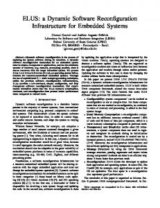
The basic architecture of MiCAP is shown in Figure 3. The MiCAP consists of 4 major parts: two asynchronous FIFO buffers, an ICAP state machine and the ICAP primitive. All the elements of the MiCAP are synchronized by a common clock with a frequency of 100 MHz. 1) Input Buffer: This is an asynchronous FIFO buffer that holds the ICAP read and write commands along with
State machine a) Wait state: In this state, the MiCAP waits until all the data (frames + ICAP commands) are filled into the input FIFO. b) Read state: The MiCAP’s read activity is triggered by the processor by setting “MiCAP_en” and “MiCAP_read_en” signals to high. In this state, first the RDWRB signal is set to high and then the ICAP primitive is enabled by setting the CSIB signal to a low value. The read command present in the input buffer is fetched and written to the ICAP’s input port. The command is written for every rising edge of the clock. Once the read command is sent, the ICAP starts fetching the configuration data. The frames fetched from the ICAP are written into the output buffer. Once the read activity is completed, the ICAP is disabled by setting the CSIB signal to high. The “MiCAP_rd_wr_done” signal is set to high once the MiCAP’s read activity is accomplished. c) Write state: The MiCAP’s write activity is triggered by the processor by setting the “MiCAP_en” signal to high and set the “MiCAP_read_en” signal to low. In this state, first the RDWRB signal is set to low and then the ICAP primitive is enabled by setting the CSIB signal to low. The write command is fetched from the input buffer and the command is written to the ICAP’s input port. Once the write command is sent, the ICAP believes that next incoming data is the configuration data that has to be written into the configuration memory of the FPGA. Now the state machine reads the data from the input buffer and writes the data into the ICAP input port. The ICAP continues to write the data sent from the input buffer into the configuration memory until the input buffer is empty. The “MiCAP_rd_wr_done” signal is set high once the MiCAP’s write activity is accomplished. We propose two versions of the MiCAP: the Basic MiCAP and the MiCAP with single port RAM. The latter version of the MiCAP contains an extra single port RAM that holds the ICAP read and write commands well before the data transaction
ICAPE2 Macro MiCAP_en
O [31:0] I [31:0]
RDWRB CSIB
specialized configuration data which is to be written into the configuration memory. The application software is responsible to store all the configuration data into the input buffer before triggering the write activity of the MiCAP. Therefore, the input buffer acts as the configuration data source for the MiCAP’s write activity. 2) Output Buffer: This is also an asynchronous FIFO buffer that holds the configuration data fetched by the ICAP primitive during the read activity. All the data read from the configuration memory via the ICAP is stored in the output buffer. Therefore, the output buffer acts as a sink to the MiCAP’s read activity. Once the data is ready, the processor has to read the frames from the output buffer. 3) ICAP primitive: This is a design element that gives access to the configuration data of the FPGA. Using this element the commands and data can be read or written into the FPGA configuration memory. The ICAP primitive architecture of the Zynq-SoC is explained in Section III. 4) ICAP State machine: This is the brain of the MiCAP. It contains multiple states that orchestrate the MiCAP’s read and write activity. The state machine contains 3 major states: Wait state, Read state and Write state. The description of each of the states is as follows.
MiCAP_rd_wr_done
Input Buffer (FIFO) Din [31:0]
ICAP State machine
Rd_en
Output Buffer (FIFO) Wr_en
Address Counter [31:0]
MiCAP_rd_en
Rd_en
Din [31:0]
Dout [31:0]
Wr_en
Wr/Rd
Dout [31:0]
Dout [31:0]
Single-port RAM ICAP RD-WR Commands Din [31:0] (Frame Address)
Fig. 4.
MiCAP with single port RAM.
begins. These commands are non-volatile in contrast to the data in the input buffer, hence the MiCAP can make use of these commands multiple times as needed. Therefore, the input buffer (FIFO) is used to hold only the specialized bitstreams (frames) that replace the stale frames present in the configuration memory. This saves significant amount of time during the reconfiguration since only the configuration frames are transferred between Processing System (PS) and PL of the Zynq-SoC. Figure 4 shows the MiCAP with single port RAM. The state machine handles the multiplexing of data between the frames from the input buffer and the ICAP commands from the single port RAM to establish the proper reconfiguration process. However, this version of the MiCAP utilizes more FPGA resources (LUTs and FFs) compared to the basic MiCAP. V.
E XPERIMENTAL S ETUP
In this Section, we describe the experimental setup of the parameterized design implemented using DCS with MiCAP. We implemented the MiCAP on a self-reconfigurable DCS platform and measured the throughput. A. FIR filter We used a 16-taps, 8-bit adaptive Finite Impulse Response (FIR) filter as a parameterized design implemented using DCS [3]. The filter taps are parameterized. Hence, for every infrequent change in coefficient input values (C1 to C16), a specialized bitstream is generated. The FIR filter is built with sixteen 8-bit multipliers (implemented using LUTs of the device) and they consume 384 TLUTs of the Zynq-SoC FPGA. This filter can be used for a DSP application in which FIR filters are used to realize the filtering of unwanted bandwidth of signals. If the frequency of the bandwidth is required to change infrequently then a parameterized FIR implementation would suit better than the classic FIR implementation. B. The self-reconfigurable platform for DCS We used a self-reconfigurable platform [11] used for building a parameterized FIR filter using DCS. The MiCAP is used as a configuration interface. The PPC Boolean functions are stored in the DRAM memory of the PS and all the actions of
TABLE I.
R ECONFIGURATION SPEED COMPARISON BETWEEN HWICAP AND M I CAP
Controller AXI-HWICAP MiCAP MiCAP with single port RAM
TLUT Reconfiguration time (µs)
Throughput (MBps)
Total Reconfiguration time(ms)
230 210
19 22
88.3 80.6
194
23
74.4
the Micro-reconfiguration are controlled by the ARM CortexA9 processor. Therefore, the user can use a simple program to run software on the processor to control and measure the reconfiguration activity. The whole system is connected using the AXI-lite bus for the data transfer. C. Performance measurement of MiCAP The parameterized FIR filter was executed on a selfreconfigurable platform. The soft timers were deployed to measure the reconfiguration time. The FIR filter coefficients were changed manually by the user to simulate the reconfiguration. With the help of soft timers, the time taken to reconfigure one TLUT was measured. The resource consumption of the MiCAP was also measured by using the Xilinx implementation report. Finally, we studied the impact of MiCAP’s reconfiguration speed on the overall DCS system.
TABLE II.
T IME EXPENDITURE
Micro-reconfiguration Task
Time (µs)
Read activity Write activity Boolean evaluation and Modify activity Total
97 95 18 210
TABLE III.
R ESOURCE UTILIZATION
Controller
FF
LUTs
BRAMs
Max. Clock freq. (MHz)
AXI-HWICAP MiCAP MiCAP with RAM
675 221 234
500 290 330
1 0 0
100 100 100
Table II shows the time distribution of the reconfiguration time for a TLUT. Clearly, the time taken to transfer the data between the processor and the PL region holds the major stake in the reconfiguration time. This is due to the inefficient data transfer via the general purpose (GP) ports of the ZynqSoC. To counter this problem, we can make use of the higher performance ports (HP). However, the HP ports cannot be accessed by the ARM processor directly. Therefore, a Direct Memory Access (DMA) module needs to be instantiated. The DMA uses the HP ports to transfer the data between the PL and the DRAM memory of the PS. This is planned for future work. B. Resource utilization
VI.
R ESULTS AND D ISCUSSION
A. Reconfiguration Speed The data transaction occurs between the PS and PL regions of the Zynq-SoC to accomplish the micro-reconfiguration. The data transfer occurs via general purpose ports (GP) of the Zynq-SoC. The DCS reconfiguration time for a single TLUT using different reconfiguration controllers is tabulated in Table I. Clearly, the time taken to reconfigure one TLUT using basic MiCAP is ≈ 10 % less than the HWICAP. The reduction in reconfiguration time was because of the optimized state machine built within the MiCAP. However, by deploying a single port RAM to store the ICAP read and write commands instead of filling the commands by the processor to input buffer FIFO, the reconfiguration speed was increased by ≈ 17 % compared to the HWICAP. The main reason for the increase is that we bypassed the data (ICAP commands) transfer between the PS and PL via the GP port. The reconfiguration time of the DCS with MiCAP can be split into three parts: 1) Read activity time: It is the time taken to fetch 5 frames (1 dummy frame + 4 frames) from the configuration memory and transfer the data to the ARM processor via the GP ports. 2) Write activity time: It is the time taken to write 5 frames (4 frames + 1 dummy frame) from the processor to the configuration memory. The frames are transfered from the processor to the input buffer (FIFO) of the MiCAP via the GP ports. 3) Modify activity time: It is the time taken to evaluate the PPC boolean function and modify the bitstreams to generate specialized bitstreams.
The FPGA resource utilization of the reconfiguration controllers is tabulated in Table III. Clearly, the MiCAP utilizes 67% less Flip Flops than the HWICAP. We also observe a reduction in LUT utilization by 42%. In addition there were no BRAMs utilized by the MiCAP in contrast to the HWICAP. In [12], authors have shown that the HWICAP is the most power hungry part of DCS. Since the MiCAP consumes less FPGA resources, we envisage that power consumption by the MiCAP is less than the HWICAP and thus proving its power efficiency. C. Functional Density The overall effect of the improvement in reconfiguration speed on the application can be best explained using the functional density curve. The functional density (Fd ) is defined as the number of computations (N) per unit area (A) and unit time (T) as shown in Equation 1. Fd =
N AT
(1)
In our experiment, the number of computations ‘N’ is all the operations executed by the FIR filter. The value of ‘A’ depends on the resources of the FPGA (mainly TLUTs). The value of ‘T’ is the sum of the filter execution time, the reconfiguration time and the time taken to specialize. The functional density curve is plotted against the rate of change of parameter values (i.e., the number of clock cycles in between two parameter changes). The functional density shows the efficiency of the implementation as a function of how fast the parameter values change. The functional density curve of the FIR filter with four different implementations (is shown in Figure 5):
curve. Improving the reconfiguration speed leads to flexibility in the parameterized design which allows the parameters to change more frequently compared to the DCS implementation using the HWICAP. The MiCAP is a custom reconfiguration controller designed to implement DCS. The source code can be accessed at [13]. VIII.
Fig. 5.
Functional Density curves.
1) Generic (without reconfiguration controller): FIR filter implemented without DCS. 2) HWICAP: FIR filter implementation with DCS using HWICAP. 3) Basic MiCAP: FIR implementation with DCS using basic MiCAP. 4) MiCAP with single port RAM: FIR implementation with DCS using MiCAP with single port RAM. In Figure 5, the x-axis represents the average time (in clock cycles) between two parameter value changes. The Generic implementation without reconfiguration has no variation in the functional density since it uses a fixed number of FPGA resources. The curve for DCS implemented with MiCAP rises before the conventional DCS because of the improvement in the reconfiguration speed and hence the parameter values are allowed to change faster than before with the same gain in area. Similarly, the functional density curve for the DCS implementation using MiCAP with single port RAM rises just before the functional density curve with basic MiCAP due to the slight improvement in reconfiguration speed. The DCS with basic MiCAP and MiCAP with single port RAM has less implementation area (less number of LUTs) therefore, the functional density of each is much higher than the DCS with HWICAP. VII.
C ONCLUSION
The reconfiguration controller plays an important role in partial reconfiguration and in particular in the DCS implementation technique. The HWICAP supplied by Xilinx can be used as a reconfiguration controller to implement the conventional DCS technique. However, the HWICAP suffers from a high communication overhead between processor and the ICAP resulting in inefficient performance. This inefficient controller architecture affects the reconfiguration speed and hence the HWICAP can provide a maximum data throughput of only 19 MBps where as the ICAP itself could potentially handle 400 MBps. Therefore, the reconfiguration speed is one of the major limitations of DCS. To counter this problem, we have proposed a custom reconfiguration controller called MiCAP. The MiCAP is built with an optimized state machine that makes the controller simple enough to support a data throughput of 23 MBps. Therefore, data throughput is significantly increased by 21% compared to the HWICAP. This helps to increase the reconfiguration speed of DCS by 17%. We have also discussed the overall effect of this improvement on the parameterized application by plotting the functional density
F UTURE WORK
In our future experiments, we would like to deploy the AXI-DMA component to the MiCAP. The DMA uses high performance ports (HP) of the Zynq-SoC for the high speed data transfer. This would reduce the time expenditure of the data transfer between PS and PL regions. Therefore, by making use of the DMA we expect a drastic improvement in the reconfiguration speed. R EFERENCES [1] A. Kulkarni, K. Heyse, T. Davidson, and D. Stroobandt, “Performance evaluation of Dynamic Circuit Specialization on Xilinx FPGAs,” in FPGAworld Conference 2014, Proceedings. Stockholm, Sweden: Association for Computing Machinery, 2014, pp. 1–6. [2] “Xilinx LogiCORE IP AXI HWICAP (v2.02.a) (ds817),” http://www.xilinx.com/support/documentation/ip_documentation/ axi_hwicap/v2_02_a/ds817_axi_hwicap.pdf, accessed: 2014-05-14. [3] A. Kulkarni, T. Davidson, K. Heyse, and D. Stroobandt, “Improving reconfiguration speed for Dynamic Circuit Specialization using Placement Constraints,” in ReConFigurable Computing and FPGAs (ReConFig), 2014 International Conference on, Dec 2014, pp. 1–6. [4] K. Bruneel, W. Heirman, and D. Stroobandt, “Dynamic data folding with parameterizable configurations,” ACM Transactions on Design Automation of Electronic Systems, vol. 16, no. 4, 2011. [5] K. Heyse, T. Davidson, E. Vansteenkiste, K. Bruneel, and D. Stroobandt, “Efficient implementation of virtual coarse grained reconfigurable arrays on FPGAs,” in Proceedings of the 23rd International Conference on Field Programmable Logic and Applications. Piscataway, NJ, USA: IEEE, 2013, pp. 1–8. [6] K. Bruneel, K. Heyse, A. Kulkarni, and D. Stroobandt, “TLUT tool flow based Dynamic Circuit Specialization,” 2012. [Online]. Available: https://github.com/UGent-HES/tlut_flow [7] K. Vipin and S. Fahmy, “A high speed open source controller for FPGA partial reconfiguration,” in Field-Programmable Technology (FPT), 2012 International Conference on, Dec 2012, pp. 61–66. [8] K. Vipin and S. Fahmy, “Zycap: Efficient partial reconfiguration management on the Xilinx Zynq,” Embedded Systems Letters, IEEE, vol. 6, no. 3, pp. 41–44, Sept 2014. [9] “7 Series FPGAs Configuration User Guide (ug470),” http://www.xilinx. com/support/documentation/user_guides/ug470_7Series_Config.pdf, accessed: 2014-05-14. [10] S. Hansen, D. Koch, and J. Torresen, “High speed partial run-time reconfiguration using enhanced ICAP hard macro,” in Parallel and Distributed Processing Workshops and Phd Forum (IPDPSW), 2011 IEEE International Symposium on, May 2011, pp. 174–180. [11] K. Bruneel, F. Abouelella, and D. Stroobandt, “Automatically mapping applications to a self-reconfiguring platform,” in Design, Automation Test in Europe Conference Exhibition, 2009. DATE ’09., April 2009, pp. 964–969. [12] A. Kulkarni, R. Bonamy, and D. Stroobandt, “Power Measurements and Analysis for Dynamic Circuit Specialization,” in ReConFigurable Computing and FPGAs (ReConFig), 2015 International Conference on, Dec 2015, pp. 1–6. [13] A. Kulkarni and D. Stroobandt, “MiCAP: A custom Reconfiguration Controller for Dynamic Circuit Specialization,” 2015. [Online]. Available: https://github.com/UGent-HES/MiCAP