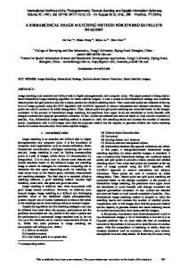
Dec 3, 2003 - multiple users, according to their positions and postures. In this paper, one of the ... camera (left) and constructed CG panoramic image. (right). Efforts are made .... ray and the incident ray; the incident ray being tangent to the desired .... zontal one by making the surface of the mirror vertically convex. Fig.20: ...
ICAT 2003 December 3-5, Tokyo, Japan
A method for panoramic stereo image acquisition Kenji Tanaka
Junya Hayashi
Tomohiro Endo
Susumu Tachi
The University of Tokyo, 7-3-1, Hongo, Bunkyo-ku, Tokyo 113-8656, Japan {tanaken, junya, yendo, tachi}@star.t.u-tokyo.ac.jp
Abstract One of the key technologies for one-to-many visual communication is panoramic stereo, in which stereoscopic images for arbitrary horizontal directions are presented to multiple users, according to their positions and postures. In this paper, one of the methods for capturing panoramic stereo motion pictures is proposed and evaluated, along with an experimentation. Through preliminary experimentation, we have confirmed the effectiveness of methods using a curved mirror. Key words: panoramic stereo, omni-directional imaging, catacaustic
1. Introduction One of the approaches to construct a vision-based communication system is to control a remote vision sensor according to the motion of an observer. An example of this approach is telexistence[1], where information such as image or sound is captured and displayed according to the head position, direction, or motion of a user. This approach can be efficient when there is only one observer, because the full bandwidth of the data channel can be used for the image presented to him/her. Meanwhile it is important to collect more information than what a single ordinary slave camera can. For example, an omni-directional image system can provide a wider FOV (field of view) view[2], which contributes to the sense of immersion. It also reduces the sense of disconfort induced by tracking error and delay, which are inevitable in a master-slave vision system[3]. On the other hand, multiviewpoint systems help multiple people to view same objects or scenes at the same time in different ways. The ideal approach is to capture and reconstruct rays at every location(Vx , Vy , Vz ), at every possible viewing angle(θ, φ), for every wavelength (λ) and at any time (t) as defined in 7D plenoptic function[4]. For instance, the NHK Science and Technical Research Laboratories developed a real-time full-color integral photography with an HDTV camera and a lens array[5]. Although it provides rays at different locations, at different possible viewing angles, for three color bands and at any time, the resolution of the output image is still very low. This is the reason why the proportion of data bandwidth for each axis of 7 dimensions has to be designed according to the application.
2. Panoramic stereo Panoramic stereo approach is characterized by capturing or reconstructing stereoscopic image for a wide FOV. For a still image, we can acquire a panoramic stereo image by panning two relatively fixed cameras. Figure 1 (left) shows that the viewpoint of each eye varies according to the viewing direction. We can also simulate the image acquisition using CG (Computer Graphics). Figure 1 (right) shows an example of a part of panoramic stereo motion picture. In this example, 360 degrees are divided horizontally into 32 equal directions where the models in the world coordinate are transformed with individual view matrices. field of view point of view
Fig. 1: Variety of point of view and field of view of left camera (left) and constructed CG panoramic image (right). Efforts are made to capture panoramic stereo images in real scene. Shum’s concentric mosaic[6] is a method for describing ray information by restricting the path of view point. However, the approach is only applicable to still images. Naemura et al.[7] have also investigated multi-user immsersive stereo for still scene. Peleg et al.[8] proposed some practical methods to capture omni-stereo motion pictures. Shimamura et al.[9] have constructed an omni-directional stereo image sensor that uses the vertical parallax to reconstruct the horizontal parallax. However it is difficult to estimate the detailed depth of objects robustly. This paper provides a solution to capture panoramic stereo motion pictures at a video rate.
3. Panoramic stereo image acquisition using cylindrical mirror In this section, we propose a practical method for panoramic stereo image acquisition. A simple method to capture a panoramic stereo image is to pan relatively fixed two cameras. However, for motion pictures, this ap-
proach fails because you have to rotate the cameras by 30 revolutions per second. In another approach, we can use optical elements instead of moving parts. A lens can be a candidate for an optical element[8]. However, with a chromatic aberration, a system using lenses can deteriorate the output image quality. Here, we focus on a system using curved mirrors. 3.1
Use of a catacaustic
An omni-directional vision sensor using a hyperboloidal mirror can generate an image taken from a single viewpoint in combination with a standard perspective camera. However, using a cylindrical or spherical mirror, the viewpoint for each viewing angle does not remain concentrated on a single point but moves continuously along a curve. This curve is called a catacaustic. Here we analyze the reflection of a cylindrical mirror. When parallel rays reflect on a cylindrical mirror, the viewpoint for each ray draws a curve (the blue curve in Figure 2). Since ”viewpoint” is defined as the limit of intersection point of two adjacent ray paths, the envelope line is calculated as follows:
�
1 (x, y) = cos3 t, (4 + 2 cos 2t) sin t 4
�
(1)
circle. Among these, for a cylindroidal mirror whose ratio of the semiminor axis and the semimajor axis is 0.8, the envelope is evaluated as:
�
(x, y) = cos3 t, 0.3125(2.2 + 1.64 cos 2t) sin t
�
(2)
The envelope becomes more like a circle, though it is still an approximation. Here we define the “catacaustic center” as a foot of a perpendicular dropped from a point on the curve where the derived function of the curve becomes zero. Figure 3 shows this situation. The blue line shows the catacaustic curve. The circularity of the arc exceeds 0.9. View points and viewing directions (orange circles and arrows) are overlaid in order to show that by collecting the reflected rays, we can capture light rays required for a panoramic stereo image sensing. Thus, we can build a panoramic stereo image sensor without a moving part using a curved mirror. A ray tracing CG simulation was conducted using a cylindroidal mirror. A cylindroidal mirror is placed at the center (Figure 4), and objects are placed at a distance of two meters. 1
(cos t, 0.8 sin t) 0.75
0.5 1 0.25 0.75
(cos t, sin t)
(?, ?)
0
0.2
0.4
0.6
0.8
1
0.5
Fig. 3: The use of cylindroidal mirror 0.25
0
0.2
0.4
0.6
0.8
1
Fig. 2: Catacaustic This curve is known to be a Nephroid[10], a special case of a catacaustic. Engineering applications of a catacaustic curve include compound parabolic concentrator[11], an array of parabolic mirror used to collect sun rays. However, image sensors using catacaustic have been relatively unexplored. A panoramic stereo image capturing using catacaustic curves is proposed by Peleg et al.[8]. Since the proposed method uses a pair of concave curved mirrors, the horizontal FOV for each eye is limited to within 180 degrees. In order to overcome the limit, we propose a method using a convex mirror. Reflections on spheres and cylinders are elaborated in [12]. 3.2
Cylindroidal mirror
Although Nephroid is not exactly a circle, it gives an approximation of a circle. As cylindrical mirrors are easier to be manufactured than mirrors of other arbitrary curves, this approximation is very important. Since the catacaustic of an ellipsoid can be solved in the same way, we can easily find a more suitable form among ellipsoids, whose catacaustic becomes a better approximation of a
Fig. 4: Settings used in the computer graphic simulation Figure 5 shows the images captured from cameras two meters in front of and behind the mirror. Figure 6 shows the reconstructed panorama image for right and left eyes. The conversion was performed so that the direction of the ray varies proportionally to the horizontal axis. One vertical line indicates that the line is copied from the corresponding line in Figure 5. In the sparse area, the horizontal resolution is relatively low. In this situation, the horizontal focal point (within the horizontal
Fig. 5: Image reflected on the cylindroidal mirror (far). Front (top) and back (bottom). plane that includes the axis of camera lens) moves along the catacaustic curve mentioned above. However, the vertical focal point exists near the camera. Thus, the vertical optics can be approximated as an afocal system, and the vertical FOV is limited by the height of the mirror. In order to widen the vertical FOV, one possible alternative is to capture the image near the mirror. Figure 7 shows a simulated image.
Fig. 8: The focus locus of near captures lation. This time, the catacaustic curve is defined as a circle, and the shape of the original surface is unknown. The exit ray is horizontal in this figure.
Fig. 6: Reconstructed images for both eyes. Right (top) and left (bottom)
Fig. 9: Calculation model The surface can be determined by solving a numerical differential equation, using a condition that the normal of the curve bisects the angle formed by the horizontal exit ray and the incident ray; the incident ray being tangent to the desired circular catacaustic curve. The differential equations are
Fig. 7: Reflected image (near) In this condition, because the catacaustic curve does not reach the point (1, 0) in Figure 8, the horizontal FOV becomes smaller and the vertical FOV becomes larger instead. There is still a problem that the distance between the vertical focal point and the horizontal focal point varies according to the direction. This makes the vertical focal point be different from the horizontal one. Furthermore, the gap will differ from left and right eyes, which can be a problem. 3.3
Exact solution
Now, we will go on to an exact calculation of the surface shape of the mirror. Figure 9 shows an exact formu-
f � (t)
=
tan
f (0)
=
1
φ 2
(3)
where φ is supplementary angle of the incident angle, and (a, b) is the tangent point to the catacaustic curve. φ
=
tan−1
at + bf (t)
=
1
=
1
2
a +b
2
b a (4)
A part of the result is shown in Figure 10. Figure 11 shows a method to draw the catacaustic shape. First entwine a rubber band around the desired catacaustic shape. One end of the rubber band is fixed at the position of camera. Starting from the top in the figure, draw a curve with a pencil. Always make the pencil move depending on or
against the resultant force of the rubber band. We can draw a mirror that is able to capture light rays incoming from directions over 240 degrees (Figure 21 upper).
Fig. 10: Part of solution of the differential equation. Fig. 12: Cylindrical mirror (left) and experimentation setup (right). Border of the mirror Desired catacaustic shape
Top View
objects
ray direction
Cylindrical mirror
catacaustics
200cm
30cm
camera
camera 12cm
rubber band
Fig. 11: Method to draw a catacaustic shape.
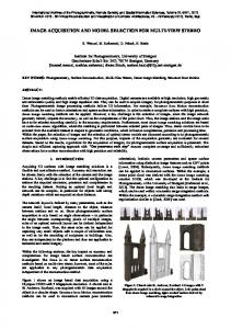
4. Experimentation In order to evaluate the feasibility of this method, we have conducted a preliminary experimentation using a cylindrical mirror (Figure 12). The mirror is an acrylic cylinder, on which aluminium vapor is deposited. The purpose of this experimentation is to find the practical range of direction, in which panorama image is reconstructed with an enough resolution. In this experimentation, we use still objects, and the image for the left eye and the image for the right eye are captured sequentially using a camera. The Camera is placed 1.8m from the catacaustic center. Shown in Figure 14 are reflected images, and shown in Figure 15 are the reconstructed panoramic stereo images. Obviously, the horizontal resolution varies according to the direction, and defines the practical range of direction angle. The relation between direction and resolution was calculated and plotted(Figure16), which coincides with a visual observation. We confirmed that the horizontal resolution remains greater than one fourth of that of the center for a range of ± 30 degrees from the
Fig. 13: Setting – pens and balls
Fig. 14: Reflected images – pens and balls
Fig. 18: Reflected images – penguins Fig. 15: Panoramic stereo for left eye (top) and right eye (bottom) front. Within that range, we could have an image of VGA resolution using an HD camera.
Resolution [ratio]
1 left eye
right eye
Fig. 19: Omni-stereo panoramas – near 0.25 0
-45
-30
0
30
45
Phi [deg]
pect ratio (r� , the apparent width divided by the apparent height) can be calculated as: r� =
Fig. 16: Relation between direction and resolution Figure 18 is another example. The camera is placed at 1.0 m from the center.
1 k1 w = k2 r 2πdh d
(5)
where k1 , k2 are constant, and r = w/h. Since the aspect ratio is inversely proportional to the distance, this effect is particularly prominence when the objects are near the center. In order to avoid this effect, one possibility is to make efforts to coincide the vertical focal point with the horizontal one by making the surface of the mirror vertically convex.
Fig. 17: Setting – penguins
5. Discussion 5.1
Aspect Ratio
As mentioned above, the vertical focal point is different from the horizontal one. This is why the aspect ratio of an object varies according to its distance from the catacaustic center. In other words, the aspect ratio of the scene varies according to the distance we focus on. As shown in Figure 20, when you focus on the penguin, yellow ball becomes tall, and when you focus on the yellow ball, the penguin becomes short. This effect is essential to this system. Using width (w), height (h) of an object, and its distance from the catacaustic center (d), the apparent as-
Fig. 20: Omni-stereo panoramas – near and far 5.2
System design
Using the knowledge above, we can outline possible designs for a panoramic stereo motion-picture capture system.One of those is a system consisted of one cylindrical mirror and two HD cameras.Cameras placed at 1 m in the right side and left side of the mirror capture a panoramic stereo image reflected on the mirror. The image is geometrically converted in real time into a panoramic stereo image.With this system, one can capture panoramic stereo
rays for a range of about 240 degrees for each eye. The panoramic stereo region for both eyes is about 90 degrees. One possible option to overcome the limit is to rotate the curved mirror around the catacaustic center. An image is captured twice per one revolution (Figure21 lower). Since off-center incident rays come from all the directions, a 360-degree panoramic stereo image is captured within one revolution without using a high speed camera. The occlusion by cameras can be avoided by using half mirrors.
approach to virtual environment navigation. In Proceedings of SIGGRAPH ’95, pages 29–38, 8 1995. 3. Carolina Cruz-Neira, Daniel J. Sandin, and Thomas A. DeFanti. Surround-screen projectionbased virtual reality: The design and implementation of the cave. In Proceedings of SIGGRAPH 1993, Computer Graphics Proceedings, Annual Conference Series, pages 135–142. ACM, ACM Press / ACM SIGGRAPH, 1993. 4. E. H. Adelson and J. Bergen. The plenoptic function and the elements of early vision. In Computational Models of Visual Processing, pages 3–20. MIT Press, 1991.
mirror
5. F. Okano, H. Hoshino, J. Arai, and I. Yuyama. Real-time pickup method for a three-dimensional image based on integral photography. Applied Optics, 36(7):1598–1603, 1997. 6. H. Y. Shum and L. W. He. Rendering with concentric mosaics. In Proceedings of SIGGRAPH 1999, Computer Graphics Proceedings, Annual Conference Series, pages 299–306. ACM, ACM Press / ACM SIGGRAPH, 1999.
Top View
camera
camera
Fig. 21: Curved mirror and its use in two-phase mode
6. Conclusion We proposed a method to capture panoramic stereo images, using a catacaustic of a cylindrical or cylindroidal mirror. We can capture off-center incident rays coming from a range of directions at a moment. Through a preliminary experimentation, we have confirmed the effectiveness of the method. Although the horizontal resolution of the obtained panoramic images varies according to the direction, we confirmed that it remains greater than one fourth of that of the center for a range of ± 30 degrees from the front. Future works include an effort to coincide the vertical focal point with the horizontal one. The proposed method can be applied to applications such as playback-type virtual reality or one-to-many realtime transmissions of immersive images. Acknowledgement This research has been supported by the CREST project of JST (Japan Science and Technology Corporation).
References 1. S. Tachi et al. Tele-existence(i)-design and evaluation of a visual display with sensation of presence. In Proceedings of RoManSy’84 The Fifth CISM-IFToMM Symposium, pages 245–254, 1984. 2. Shenchang Eric Chen. Quicktime vr – an image-based
7. Takeshi Naemura, Masahide Kaneko, and Hiroshi Harashima. Multi-user immersive stereo. In IEEE Int’l. Conf. on Image Process. (ICIP’98), volume I, pages 903 – 907, 10 1998. 8. S. Peleg, M. Ben-Ezra, and Y. Pritch. Omnistereo: Panoramic stereo imaging. IEEE Trans. on PAMI, pages 279–290, 2001. 9. J. Shimamura, N. Yokoya, H. Takemura, and K. Yamazawa. Construction of an immersive mixed environment using an omnidirectional stereo image sensor, 6 2000. 10. Christiaan Huygens. Traite de la Lumiere. 1692. 11. R. Winston and Walter T. Welford. High Collection Nonimaging Optics. Academic Press, 1989. 12. Georg Glaeser. Reflections on spheres and cylinders of revolution. In Journal for Geometry and Graphics, volume 3, pages 121 – 139, 1999.