Abstract. In this paper, we propose an efficient stereo image rectification method using the horizontal baseline. Since the stereo camera is generally manually ...
Efficient Stereo Image Rectification Method Using Horizontal Baseline Yun-Suk Kang and Yo-Sung Ho School of Information and Communicatitions Gwangju Institute of Science and Technology (GIST) 261 Cheomdan-gwagiro, Buk-gu, Gwangju 500-712, Republic of Korea {yunsuk,hoyo}@gist.ac.kr
Abstract. In this paper, we propose an efficient stereo image rectification method using the horizontal baseline. Since the stereo camera is generally manually arranged, there are geometric errors due to the camera misalignment and the differences between the camera internal characteristics. Although the conventional calibration-based stereo image rectification method is simple, it has an opportunity to provide the results that have some visual distortion such as image skewness. Therefore, the proposed method calculates the baseline for stereo image rectification, which is parallel to the horizontal line in the real world. Using this baseline, we estimate the camera parameters and the rectification transform. By applying the transform to the original images, we obtain the rectified stereo images. Experimental results show that the results of the proposed method provide the better rectified stereo image without visual distortion. Keywords: Image rectification, stereo image, stereo camera, 3DTV.
1
Introduction
Three-dimensional (3D) TV provides us more realistic video contents than the current two-dimensional (2D) television broadcasting. Since the input signal of 3DTV is composed of more than single viewpoint images or videos, users can watch the scene with immersive feeling. In recent years, much research on 3DTV and 3D content generation has been investigated to satisfy the increasing demands for realistic multimedia services in the world [1]. In order to generate 3D contents for 3DTV, at least two view images are required basically. Two cameras, called the stereo camera, capture a 3D scene or object in the real world from two different positions. Users watch this stereo image with 3D sense with stereoscopic displays. Moreover, from this stereo image, we can estimate the scene’s depth information using stereo matching [2], and also generate novel view images based on the depth. However, there is a constraint to use stereo images for 3D applications. Two image planes of the stereo camera determine their epipolar geometry that satisfies the epipolar constraint between two images. Epipolar constraint is that a point in one image has its corresponding points in the other image along an epipolar line. Y.-S. Ho (Ed.): PSIVT 2011, Part I, LNCS 7087, pp. 301–310, 2011. © Springer-Verlag Berlin Heidelberg 2011
302
Y.-S. Kang and Y.-S. Ho
Therefore, if the epipolar lines l in each image plane are parallel, the correspondding points have the same vertical coordinates. In other words, there is no vertical piixel difference between two im mages. In this case, the stereo image has only horizonntal displacement. The visual quality q of the image as the 3D contents increases and aalso the stereo matching processs becomes very simple [3]. Unfortunately, the practtical stereo image captured by a manually arranged stereo camera does not have the parallel epipolar lines. Therre are not only position and orientation differences but aalso internal parameter differencces between two cameras. In order to solve these problems p in stereo images, we perform image rectificatiion. Image rectification is rotatio on and movement of two image planes that makes epipoolar lines parallel each other. The rectified stereo image is then considered as the imaages captured by two physically--equal cameras with only horizontal camera interval. Image rectification has been b studied for long time. There are two categories; onne is based on the image features [4] [5], and the other is calibrated case [6] [7]. Recenntly, rectification has been exten nded to cover the multiple views [8]. In general, the reesult of image feature based rectiification has some visual distortion such as image skewiing. It is also influenced by th he extracting features. While the calibration based im mage rectification gives more stable s results and rectified camera parameters whichh is essential information for 3D 3 applications. However, the stereo cameras have too be calibrated before the rectificcation, and the reliability of calibration is also influencee on the results. In this paper, we explain n a stereo image rectification method using the horizonntal baseline. We introduce thee stereo geometry briefly in Section 2. In section 3, we explain the proposed metthod. After scene capturing and camera calibration, we calculate the horizontal basseline for rectification. Using this baseline, we estimate the rectification transform. By applying this transform to the original stereo image, we obtain the rectified stereo im mage. After showing the experimental results in Sectionn 4, we conclude this paper in Section S 5.
Fig. 1. Stereo geometry
2
Stereo Geometry
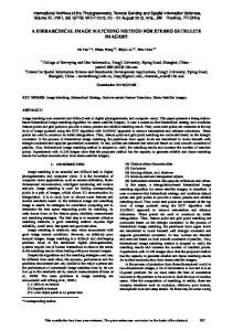
Figure 1 shows the geomettry of stereo image. There are two camera centers C1 and C2, and the object at the po oint M in the 3D space. These three points are in the woorld
Efficient Stereo o Image Rectification Method Using Horizontal Baseline
303
coordinate system, and two o cameras also have their own coordinate systems. E Each camera coordinate system has h three axes; vertical, horizontal, and principal axes. T The principal axis is also called d the optical axis, which indicates the optical ray directtion of the camera. By operating two cameraas, the object located on M is projected to the image pooints m1 and m2 in each image plane. The corresponding point of m1 in the right im mage plane has to be on the epiipolar line. The epipolar line of the right image planee is defined as the intersecting line l between the right image plane and the plane descriibed by M, C1, and C2, which is called the epipolar plane. Figure 2 shows the geo ometry of the rectified stereo image that has the paraallel epipolar lines in each imaage plane. All the points in the Fig. 2 excluding M are changed and also each im mage plane is rotated and moved. Therefore, two im mage planes and epipolar lines arre parallel to the line through C’1 and C’2 which is callled the baseline. In this case, two image points m’1 and m’2 have the same verttical coordinates. It means thaat there is no vertical pixel displacement between ttwo corresponding points.
Fig. 2. Rectified stereo geometry
3
Proposed Stereo Image I Rectification Method
In this section, we explain n our proposed method to rectify the stereo image. In the conventional method bassed on the camera parameters [6], the baseline for rectification is determined as a the line through C1 and C2 in Fig. 1. Then, C’1 and C’2 are the same as C1 and C2 after rectification. If this baseline is not parallel to the horizontal line in the real world, w the rectified image can be skewed with respect to the users’ view. Therefore, the proposed d method calculates the baseline that is parallel to the horizontal line in the reall world. Figure 3 shows the procedure of the propoosed method. After scene captturing, we estimate the camera parameters by cam mera calibration [9]. By using th hese camera parameters, we calculate the baseline whichh is parallel to the real horizonttal line, and then we estimate the camera parameters off the
304
Y.-S. Kang and Y.-S. Ho
rectified stereo image based on the baseline. Finally, we obtain the rectified stereo image by applying the rectification transform to the captured images. This transform is computed using both of the original and estimated camera parameters.
Fig. 3. Procedure of the proposed method
3.1
Baseline Calculation
After obtaining camera the parameters by camera calibration, we calculate the baseline. Baseline calculation begins with the initial line which is obtained by connecting the two camera centers. From this initial line, we can calculate the baseline. The baseline must satisfy the following two conditions. First, this baseline and the initial line are on the same plane that has its normal vector as the direction of the new principal axis. The new principal axis is determined as the direction orthogonal to both of the initial line and the average direction of all the original vertical axes. It means that the baseline can preserve the orientation of the camera array which is obtained based on camera positions. The second condition is that the baseline is parallel to the horizontal line in the real world. It guarantees that the rectified stereo image according to this baseline does not have the skew problem. In order to obtain such a baseline, we use a line image projection algorithm that requires an image containing a short and non-tilted line like Fig. 4(a). Through the line image projection, we can measure the slope of the initial line, and then we can calculate a suitable correction vector to make the baseline parallel to the real horizontal line.
Fig. 4. Line image projection
Efficient Stereo Image Rectification Method Using Horizontal Baseline
305
In order to measure the slope of the initial line, we assume that the line image is left of the stereo view. We then project this image so that the horizontal axis of the image plane is parallel to the initial line. As a result, the projected image has the line tilted as the slope of the initial line as indicated in Fig. 4(b). We can measure the slope of this line by counting the number of pixels between the start-point and the end-point of the line. This measured value means the slope of the initial line. After measuring the slope of the initial line, we need a correction vector to obtain the baseline that satisfies the second condition. Figure 5 shows how to calculate the correction vector. The cross product between the new principal axis and the initial line vector makes the orthogonal vector. The correction vector is then calculated as the sum of the initial line vector and the orthogonal vector.
Fig. 5. Correction vector calculation
Fig. 6. Baseline calculation
In order to calculate the baseline, we measure the slope of the correction vector. By using the line image projection again, the projected image in accordance with the correction vector has an opposite slope to the initial line like Fig. 4(c). Finally, we can calculate the baseline which is parallel to the real horizontal line by summing the initial line vector and the correction vector with a proper scale factor. Let i and c be
306
Y.-S. Kang and Y.-S. Ho
the slopes of the initial line vector and the correction vector, respectively. The scale factor s is defined as the ratio of i and c. The baseline vector is then calculated as Eq. 1 where and mean the initial line vector and the correction vector, respectively. Figure 4(d) shows the baseline that is parallel to the real horizontal line. This process is indicated in Fig. 6.
(1)
3.2
Camera Parameter Estimation
After calculating the baseline, we estimate the rectified camera parameters. We firstly find the new camera centers. In the proposed method, the left camera center is considered as the reference and we estimate the new camera center of the right camera. Then the new camera center of the right camera is defined as a point that is apart with the user-input camera distance along the direction of the baseline. After that, we consider the camera rotation matrices. We estimate each camera rotation matrix that satisfies the following conditions. The horizontal axis of every image plane becomes parallel to the baseline vector. All the principal axes are defined in common as the direction perpendicular to both of the baseline vector and the average of all the original vertical axes. Then, the vertical axis of each image plane is orthogonal to both of the new principal axis and the baseline vector. Thus, the rotation matrix for the rectified stereo camera R’ has the form shown in Eq. 2, where and mean the directions of the baseline vector and the average of all the original vertical axes, respectively.
(2)
Then, we estimate the common camera intrinsic parameters. The focal length and the principal point are obtained as the averages of their original values, respectively. The same focal length of each camera makes all image planes coplanar. There are also uniform horizontal displacement between corresponding points and few vertical mismatches in pixels between corresponding points due to the same principal point of each camera. Finally, we obtain the rectified camera projection matrices which are composed of the estimated camera parameters like Eq. 3. (3)
Efficient Stereo o Image Rectification Method Using Horizontal Baseline
3.3
307
Rectification Transfform
For the last step, we can generate the rectified stereo image by calculating and applying the rectification transform. We consider the epipolar geometry for eeach he point-to-point mapping between images of the origiinal viewpoint. Then, we use th and estimated cameras calleed the 2-D homography H [10]. Finally, the transform m for k-th image is obtained by y using this homography like Eq. 4. By applying this transform to each image, wee can obtain the rectified stereo image. (4)
4
Experimental Ressults
For experiments, we capttured two sets of stereo image. We used two typess of cameras; one provides 10 024x768 and the other provides full HD (1920x10080) resolution. The first test im mages are shown in Fig. 7(a), the distance between ttwo cameras is about 6.5cm. Th he second test images are shown in Fig. 7(b), the distaance between two cameras is 40 0cm in this case. Figure 8(a) and Fig. 8(b) show that the captured images have the practical p stereo geometry which is shown in Fig. 1. Thhere were vertical pixel displacement between corresponding points, and also we notice the camera rotation differen nce.
(a) Yut-game(1024x768)
(b) Bear(1920x1080) Fig. 7. Captured images
308
Y.-S. Kang and Y.-S. Ho
Figure 9 shows the rectiified result by the conventional method [6]. We notice tthat the rectified images are skewed. s This skewness is due to the skewed baselline connecting the original C1 and a C2. Especially for the second image set, although thhere is a little geometrical misaalignment in the original images, the rectified results hhave more visual distortion.
(a) Synthetic image of Yut-game Y
(b) Synthetic image of Bear
Fig. 8. Syn nthetic images for the captured stereo images
(a) Yut-game
(b) Bear Fig. 9. Skewed result images
Figure 10 shows the rectified stereo images and their synthetic images by the wn in Fig. 10, the result images are not only rectified w well proposed method. As show but also almost parallel to o the horizontal line in the real world. It is because the
Efficient Stereo o Image Rectification Method Using Horizontal Baseline
309
baseline for rectification is calculated to be parallel to the real horizontal line. Alsoo, as shown in Fig. 10(c) and Fig g. 10(d), there are few pixels of vertical difference betw ween corresponding pixels.
(a) Yut-game
(b) Bear
(c) Synthetic image of Yut-game Y
(d) Synthetic image of Bear
Fig g. 10. Results by the proposed method
5
Conclusion
In this paper, we presented d a stereo image rectification method using the horizonntal baseline. The proposed metthod avoids that the rectified images become skewed due to the miscalculated baseline. The baseline in the proposed method is calculated too be parallel to the horizontal lin ne in the real world using the initial and correction vecttors calculation. Therefore, thee experimental results show that the results from the proposed method have less geometrical misalignment without the visual distorttion compared to the convention nal method.
310
Y.-S. Kang and Y.-S. Ho
Acknowledgements. This research was supported by the MKE(Ministry of Knowledge Economy), Korea, under the ITRC(Information Technology Research Center) support program supervised by the NIPA(National IT Industry Promotion Agency) (NIPA-2011-(C1090-1111-0003)).
References 1. Smolic, A., Kauff, P.: Interactive 3D Video Representation and Coding Technologies. Proc. of IEEE, Spatial Issue on Advances in Video Coding and Delivery 93(1), 99–110 (2005) 2. Sun, J., Zheng, N.N., Shum, H.Y.: Stereo Matching Using Belief Propagation. IEEE Transactions on Pattern Analysis and Machine Analysis (PAMI) 25(5), 787–800 (2003) 3. ISO/IEC JTC1/SC29/WG11 M12030: Comments on Input and Output Format of MVC (2005) 4. Hartley, R.: Theory and Practice of Projective Rectification. International Journal of Computer Vision 35(2), 115–127 (1999) 5. Loop, C., Zhang, Z.: Computing Rectifying Homographies for Stereo Vision. In: Proc. of IEEE Conference on Computer Vision and Pattern Recognition (CVPR), pp. 125–131 (1999) 6. Fusiello, A., Trucco, E., Verri, A.: A Compact Algorithm for Rectification of Stereo Pairs. Machine Vision and Application 12(1), 16–22 (2000) 7. Kang, Y., Lee, C., Ho, Y.: An Efficient Rectification Algorithm for Multi-view Images in Parallel Camera Array. In: Proc. of 3DTV Conference 2008, pp. 61–64 (2008) 8. Kang, Y., Ho, Y.: Geometrical Compensation for Multi-view Video in Multiple Camera Array. In: Proc. of International Symposium ELMAR, pp. 83–86 (2008) 9. Camera Calibration Toolbox for Matlab, http://www.vision.caltech.edu/bouguetj 10. Hartley, R., Zisserman, A.: Multiple View Geometry in Computer Vision. Cambridge University Press (2003)