Protocols may follow different paradigms, such as, for example, multi rendez- vous, call-return ... exchanging data and control on their communication channels. In a typical top- .... English manuscript, a set of marketing requirements, etc. This must be ..... DAC'91: 28th ACM/IEEE Design Automation Confer- ence, San ...
A M e t h o d o l o g y for S y s t e m - L e v e l D e s i g n for Verifiability * Paolo Camurati, Fulvio Corno, Paolo Prinetto Politecnico di Torino, Dipartimento di Automatica e Informatica, Turin, Italy
A b s t r a c t . Working at system level is attracting increasing interest. New issues must be taken into account, such as validation and verification at all steps. This paper presents a system-level design methodology that supports verification. Starting from a description in a proper subset of VHDL, a Petri Net description is obtained and used for validation purposes and for building the corresponding automaton. An efficient BDDbased tool for Process Algebra manipulation supports formal equivalence proofs. Experimental results show that the approach is feasible also for real-size industrial cases.
1
Introduction
The boundaries of hardware description are rapidly migrating towards higher and higher levels of abstraction. Until not long ago, designers mainly worked at register-transfer level, whereas new activities are now emerging. A m o n g the most relevant ones, we list specification description and validation, and system-level description and verification. A system's specification generally requires a description of its evolution along time in terms of actions and events it receives as inputs or produces as outputs, as they would be seen by an external observer that knows nothing about the inner structure or behavior. At this level, the system is seen as a single process, communicating with the outside world through "communication channels". A data type and a protocol are associated to each channel. Data types vary according to user needs: a nonexhaustive list includes bit-vectors, integers, events, enumerated data types, etc. Protocols may follow different paradigms, such as, for example, multi rendezvous, call-return, send-and-forget, set-and-forget, etc. The behavior of the process can be described resorting to "prescriptive techniques", based on the definition of properties of the system or to "descriptive techniques", based on abstract models of the system [13]. Moving down one level toward more details, a partitioning of the tasks takes place and the system can be seen as several processes that concurrently evolve, * This work has been partially supported by the ESPRIT Working Group 6018 "CHARME-2" and by the Italian National Research Council project Progetto Spe-
ciale "Specifiche ad Alto LiveUo e Verifica Formale di Sistemi Digitali".
81
exchanging data and control on their communication channels. In a typical topdown design approach, in this early phase the hardware, firmware, or software implementation of components should still be an irrelevant choice, in order to allow an unconstrained exploration of alternatives, without over-limiting designers' freedom. Partitioning is iterated a number of times, until each process refers only to behaviors that are assumed to be primitive. At this stage, implementation details should not bother the higher-level specification. Communication channels could, for example, have different data types or protocols, each being adequate to its level. In this case, suitable correspondences must be defined by the user to make two adjacent levels comparable. Projection and hidin# on both the data types and the protocols seem to be a suitable choice. This design methodology is naturally depicted by an "abstraction tree", representing the relation among each process and its implementation. As in topdown design, the root is the system-level description, whereas the leaves refer to elementary behaviors, communicating with protocols that are native for the adopted technology. The goal is not to provide yet another design methodology, rather to support verification at all steps, defining a theoretical framework and providing some tools. Designing with constraints imposed by mechanized verification is a form of design for verifiability, where designer's freedom is limited by the design methodology in order to guarantee verifiability. The proof of functional correctness mainly consists in showing that a specification and one of its possible implementations are equivalent, given a suitable notion of equivalence, e.g., observational equivalence for Process Algebras [15], trace equivalence for FSMs [12], or testing equivalence [7]. The choice of the particular definition depends on the degree one is allowed and interested in looking into the internal behavior of the processes to be proven equivalent. Properties are mainly related to the temporal behaviour and Temporal Logic [2] is a good formalism to express them. Symbolic Model Checking algorithms provide an efficient way to perform checks [1]. In a critical assessment of the formalisms proposed in the literature with respect to description and verification at system-level, Temporal Logic's applicabilRy is limited to properties, i.e., to partial specifications. Extensions to FSMs [10], [17] have as a major limit their inability to define a meaningful notion of equivalence and abstraction. In the case of programming languages such as C or ADA, the eventual link to hardware is not supported. VHDL [11], with its notion of processes and signals, can be a valid choice, especially as designers are familiar w i t h it, but it wasn't intended to support formal proofs, rather simulation. A system-level design and verification methodology requires a considerab|e effort to both provide a format acceptable to designers and support for formal proofs. The formal model for the internal representation are Process Al#ebras [14], [15], whereas the designer interface is based on VHDL. Process Algebras support in a uniform way description, validation, verification, with proof algorithms [3] that can be efficiently implemented to deal with real-world systems
82
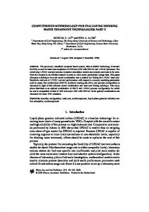
[5]. User input is translated from VHDL to Process Algebras with a two-stage process (Fig. 1), resorting to an intermediate Petri Net model. The VHDL description is translated in an annotated Predicate-Transition Petri Net, which is input to EVAL [8], an industrial verification tool able to animate, check properties, compose and reduce Petri Nets. Nets are then translated by EVAL to an equivalent Process Algebra form. A BDD-based tool is used to run formal proof algorithms on the Process Albegra description. System descriptions can thus be written in VHDL or directly as Petri Nets or Process Algebras. The verification methodology is open to other input formats, as long as a Process Algebra translation is possible. |llllmmmlmlWIIIIIIlIWlllllmmNullll L i
9
a
i
"
USER
=
.= =
Fig. 1. The flow of information
Section 2 presents the design methodology, comprehensive of the description and of the verification phases. As the communication model is crucial in system-level descriptions, it is dealt with in Section 3. Section 4 shows how Process Algebras can be interfaced to the system-level description and verification methodologies, serving as a lower-level, but efficient tool for formal proofs. Section 4 introduces an example and experimental results, whereas Section 5 draws some conclusions.
2
The
Design
Methodology
A comprehensive design methodology should be able to guarantee the verifiability of each design step, from the initial system specification to the final implementation. The approach we present here aims at this goal resorting to the specific set of tools described in the following Sections. As verification is driven by the available tools, it is necessary to restrict designers' freedom, so that a set of rules are obeyed that guarantee the applicability of the tools themselves. Such restrictions are collected in a set of "Design for Verifiability" rules [16], [4], like what happened in the field of testing with "Design for Testability" [18].
83 2.1
Definitions
"A system is a model of some portion of the real world that evolves along time, exchanging with the external environment information items, namely synchronizations and data". An implementation is a description of the system in terms of building blocks. Eventually, the building blocks become elementary for the environment, e.g., software procedures, programming language primitives, complex functional models, cell libraries, etc. The model that is assumed for system evolution is that of discrete events occurring along time and whose effect is to change the internal state of the system and/or to trigger a communication with the environment. Explicit time references are not allowed: only a discrete branching structure of time is used, with a complete before/after ordering relation between events.
2.2
Verification M e t h o d o l o g y
The goal of verification is to establish the correctness of the implementation with respect to the specification, i.e., the existence of a relation between the two which takes into account those aspects which are considered of relevance. Depending on the form in which specification and implementation are described and on the detail one wants to extract from them, several possible relations are of interest. In particular, the tools presented in this work support the proof of the following relations: hi-simulations, property satisfaction (model checking), testing relations (equivalences and preorders). System complexity often prevents verification in one step, i.e., direct proof of the relation between specification and the implementation based on elementary building blocks. This problem must be solved by describing the design process, from the specification to the implementation, as a sequence of refinement steps. This effectively bridges the gap between the two by providing several intermediate descriptions, such that verification is possible for each adjacent pair. The refinement steps of the design process start with a first formal specification of the entire system, from some informal description such as an idea, an English manuscript, a set of marketing requirements, etc. This must be validated, normally by means of test case simulation. Each following step lies between two formally specified descriptions, the specification and the implementation at that level, to emphasize that the latter is obtained by refining the former. Of course, the implementation at a level becomes the specification for the the next one, until the final implementation in terms of elementary building blocks is obtained.
2.3
Description Methodology
In order to guarantee the correct verification of the output of a design step, some constraints on the aforementioned model are imposed.
84
DFV rule # 1 At each step the system must be described as a set of concurrent processes, which communicate among themselves and with the external environment through communication ehar~nel8 (CCs). The goal of this rule is to enable verification tools to adopt the model that is commonly used by Process Algebras, leading to enhancements in system partitioning and in the use of hierarchy.
DFV rule # The output of each design step, no matter how it is obtained, must coincide with one of the intermediate descriptions used for the verification purposes. The rationale behind this rule is the need to verify each design step. Additional descriptions, not needed if design were the only issue, can be introduced for verification purposes, only. For instance, if mixed-level verification is adopted, additional system descriptions must be provided, namely the ones in which a component is detailed while the rest of the system is at a higher level of abstraction. The behavior of each component process can be described according to prescriptive or descriptive techniques. The former ones are related to properties the system should possess, the latter ones to its behavior in terms of abstract models. Properties are commonly used by designers as partial specifications that cover limited aspects. Due to their nature, particular care must be taken in their selection, trying to cover all or as many good and bad features as deemed necessary. They are usually expressed as assertions in some multi-level hardware description languages (HDL), such as VHDL [11] or in Temporal Logic [2]. Descr@tive ~echniques require a formalism which, at each refinement step, musti -
-
-
be expressive enough to catch any aspect considered relevant at that step; support mechanized verification of these aspects; be acceptable by designers and support links to major CAE systems.
A major problem is that no formalism supports the three requirements: the description methodology must allow the adoption of the best satisfying formalism for each aspect. In order to consistently support different formalisms, it must be possible to translate a description in one formalism into a description in any of the other formalisms, preserving the relevant aspects of the former. As a consequence, once again restrictions must be imposed on the use of a formalism in the form of DFV rules, that guarantee that such translation is possible. As a starting point, the following formalisms have been considered: - VHDL [11], the industry-standard HDL;
85 - the EVAL [8] input description language, based on Predicate-Transition Petri Nets [9] annotated with Prolog predicates; - Process Algebras, used as the mathematical underlying model but not directly accessible by designers. Briefly, DFV rules for different formalisms basically ensure the possibility of translating them, directly or through intermediate steps, in Process Algebra. For instance, VHDL support is accomplished by a multi-step translation process: 1. the VHDL source of each process is translated to Petri Nets, annotated with state variable values; 2. the Petri Net description is input to EVAL, which handles communications and hierarchy between different processes; 3. EVAL is used to automatically generate an automaton (an agent in Process Algebra terms) for each process or group of processes, up to the automaton of the complete system; 4. the (partial or complete) automaton description of the system is input to a BDD-based tool implementing Process Algebra operations and proof procedures. This allows us to combine the expressive power and the popularity of VHDL with the animation facilities of Petri Nets and EVAL and, finally, with the support to formal verification provided by Process Algebras.
3
The
Communication
Model
In modeling system behavior, it is assumed that any communication between processes is accomplished through communication channels. Each CC is possibly connected to several senders and several receivers, allowing different forms of m a n y - t o - m a n y communications. There is no difference between an internal channel and a channel communicating with the environment, except for the possibility of hiding internal CCs to abstract from unnecessary detail. Formally, a communication channel is defined by the 4-tuple CC = {MS, CP, CR, DR}
where: - M S specifies the message set, i.e., the set of information messages that can
be transmitted through the channels; - C P specifies the protocol that the communication flowing through C C obeys; - C R specifies the composition rule, i.e., the rule to be followed in composing
messages provided by multiple transmitters; - D R specifies the dispatching rule, i.e., the rule to be followed in dispatching
the messages to potential receivers.
86 DFV
rule #3
The message set able and finite.
MS
of a communication channel
CC
must be enumer-
The goal of this rule is to impose a constraint on the possible values flowing through channels in order to guarantee that the composite system is still finite state. Synchronization c h a n n e l s are a special kind of channels not used for data transmission, but just for synchronization. The model smoothly handles this case by defining an appropriate message set M S = {2_} for synchronization channels, where _1_is a d u m m y value. In the general model for communication channels, some specific cases have been considered, in particular those C C types that are often used by designers. Three alternative c o m p o s i t i o n r u l e s control the interaction of multiple senders over a single channel: -
-
-
= " a l l " : all transmitters must be ready to transmit for communication to happen. This models synchronization among transmitters; C R = " o n e " : at most one transmitter at a time is granted access to the channel, thus implementing a sort of mutual exclusion; C R -~ " s o m e " : no restriction is imposed on the number of actual transmitters.
CR
In the case of multiple senders over a non-synchronization channel, actual data values must agree for the communication to occur. Symmetrically, three alternative d i s p a t c h i n g r u l e s are defined to control the set of receivers to which the incoming message is delivered: all receivers get a copy of the message; at most one receiver receives the message; " s o m e " : no restriction is imposed.
-
DR
= "all":
-
DR
= "one":
-
DR
=
Based on the analysis of the currently used communication models, four are introduced, modeling different physical interpretations for logical channels. There may be multiple transmitters or receivers, according to the aforementioned composition and dispatching rules: protocols
-
-
C P = " m u l t i - r e n d e z - v o u s " : communication takes place when the sender is ready to send and the receiver is ready to receive. At that point, communication is accomplished simultaneously by all involved transmitters and receivers. This protocol is particularly useful when describing high-level synchronization structures disregarding their implementation. CP = "call-and-return":the sender transmits and "holds", awakening the receiver which is waiting for a message. Only when the receiver acknowledges the end of the task triggered by the message, the sender is allowed to resume its activity. This communication model strictly mimics calling conventions for software, with added support for concurrent subroutines (multiple receivers) and shared computational resources (several senders).
87
-
-
4
CP = "send-and-forget": the t r a n s m i t t e r emits an event, i.e., a value that appears for an instant on the bus. The event is read if the receiving side is ready to accept a message; otherwise, it is lost. This protocol easily models asynchronous, interrupt-driven designs, where receivers are edge-triggered devices. C P -~ "set - a n d - f o r g e t " : the t r a n s m i t t e r writes a value on the channel. At any time, the receiver is allowed to read the most recent value written on it. This model is particularly suited for describing latched values, which are being polled by the receivers.
Process
Algebras
The basic Process Algebra model is defined and it is shown how the richer system evolution model presented in the previous Sections can be m a p p e d onto it. 4.1
Definitions
In Process Algebra, a system is defined as several processes interconnected by means special operators. Each process is allowed to evolve by exchanging actions with the external environment. Moreover, a process m a y evolve via an invisible or internal action, identified by the symbol r. The evolution of a process is defined by a Labeled Transition S y s t e m L T S -(S, A, R, so), where: - S is the set of states of the process, and so E S the initial state; A is the set of ezternal actions the process is allowed to exchange: this set is called the sort of the process and identifies the communication ports available to the process itself; - R is the Transition Relation, R C_ S • 2 A • S, which characterizes the evolution of the system from a state to another state by means of a transition labeled by a set of external actions. Evolution by internal actions T is modeled by the e m p t y set. -
Operators are defined that build composite processes starting from simpler ones. Each operator is given an operational semantics interpreted on LTSs, defining the structure of the resulting LTS starting from the component ones. The Process Algebra adopted for this work is a variant of Circal [14], consisting of operators for action prefixing, internal choice, ezternal choice, parallel composition, hiding, and relabeling. The form of communication allowed between processes is defined by the parallel composition operator: whenever two processes are composed in parallel, their c o m m o n communication ports (those appearing in both sorts) are connected. The channel type is forced to be a synchronization one, with a strict multi-rendez-vous protocol, where composition and dispatching rules are of type "all".
88 The next two subsections explain how the complex communication model described in the previous section may be implemented with the rather primitive Process Algebra communication paradigm. The possibility of linking the two representations justifies the adoption of the high level communication channel model in formal descriptions, as their semantic is implicitly defined by the translation rules. 4.2
Value-passlng
The mapping of a valued CC with a message set M S to Process Algebra channels is based on enumerating the possible values. Care must be taken to avoid unnecessary channels: the possibility of specifying contemporary actions will be used to exponentially reduce the number of needed channels. A CC with a given M S r {A_} will be implemented as a strobe channel and [log2(IMS[)] data channels, with a n associated binary encoding for the possible values taken from MS. Communication over this channel is defined by the following rules: 1. when no communication occurs, no event is allowed on the strobe channel, but no constraints are imposed on data ones; 2. when a value is transmitted, an event is generated on the strobe channel and concurrent events are generated on the data channels corresponding to the ones in the binary encoding of the intended value. This encoding algorithm for valued communication channels has the desired property of denying synchronization between messages carrying different values. Moreover, as the strobe channel is unique, the set of data channels is forced to act synchronously, supporting the notion that they are all part of a single CC. 4.3
Protocols, Composition and Dispatching Rules
In order to model complex protocols resorting to the native multi-rendez-vous protocol for Process Algebras, special protocol handler processes are added between transmitters and receivers, constraining communication to obey the desired protocol. Handling of composition and dispatching rules is quite easy since it consists in listing the allowed communication combinations and placing, by means of the parallel composition operator, the constraining process between the communicating ones. In order to increase modularity, this process is built by the composition of several simpler ones, each one connected to a potential sender or receiver (Fig. 2). Each process is responsible for a local choice according to the desired rule and the parallel composition operator is used to extract a global behavior consistent with all the possible local choices. It is important to notice that, despite the daisy chain connection of handlers, no priority is imposed to the processes: all possibilities are taken into
89
~
mmmI | I H | | | | | | | | | | I | | |
~
~
Im||l||l|m|lll
~
Transmitters
f|lll||ll|||m||lm||||l|ll|m|llll||~
...............
I
DR
I
Fig. 2. Placing protocol handlers account and, when more than one is possible, a nondeterministic choice is taken. Moreover, this mechanism adds no complexity to the system since the handler processes are purely combinational ones, having only one state. No sequential behavior overhead is imposed on the system for modeling purposes. As an example, protocol handlers for different composition rules for multirendez-vous protocols are detailed as follows, where the daisy-chain inputs and outputs are i and o, respectively and the communication channel with the actual process is ~: -
-
"all":
P =
(i o
z)P;
"8ome": P = (i o ~)P + (o ~,)P + (i o)P; "one": P = (i o ) P + (o ~)P;
Besides the composition and dispatching rules, the protocol is handled by a separate process, modeling the temporal constraints between transmission and reception, and, when applicable, the memory possessed by the channel. 5
Experimental
results
The system implementing the translation and verification task is composed by a VHDL to Petri Net translator, by the EVAL software and by a BDD-based formal verification tool for Process Algebras [5]. The VHDL translator is currently being implemented, the home-made software amounts to about 15,000 lines of C code and runs on a Sun 4/75 SparcStation2 with 32 Mbytes. Experimental data concern an improved version of the example of [6], i.e., computers willing to exchange information items over a shared bus with a simple communication protocol. A VHDL description of the system was manually translated to Petri Nets. EVAL was then used to generate a Labelled Transition System, which was processed by the symbolic proof algorithms.
90 In Tab. 1 columns 2 and 3 report the number of states and transitions of the systems. Column 4 shows the CPU time needed to check for equivalence with the higher level specification.
'
Ibus,2 66 bus-3 [13441
CPU
2771 24 3 7 1
a8.2 I 1 420.8
Table 1. Experimental data
Proofs of typical temporal properties of the bus, such as: -
-
s a f e ~ y ("bad things will never occur"), e.g., no message will be delivered to the wrong receiver; l i v e n e s s ("good things will occur in the future"), e.g., all requests to send will eventually be served
are performed in a matter of minutes. A bug was found, as the protocol wasn't deadlock-free.
6
Conclusions
Working at system-level is attracting increasing interest from both the industrial and the academic world. New issues must be taken into account, such as validation and verification at all steps. The main contribution of this paper is a comprehensive system-level design methodology that supports at each step formal verification of correctness. In order to make designers use a formal tool without the need for a profound reconversion, a subset of VHDL has been chosen as the input description formalism. This also allows a link to existing CAE frameworks. A Petri Net description is automatically extracted and the EVAL package is used to validate it and to produce automatically the corresponding automaton. This is the semantic structure used by a Process Algebra manipulation tool to perform various kinds of proofs, based on different notions of equivalence. The tool is efficient, as it is based on BDDs and symbolic traversal techniques. Future work will consist in the mechanization of the translation from VHDL to Petri Nets and on providing data on industrial examples.
References 1. B arch, J.R., Clarke, E.M., Long, D.E.: Representing Circuits More Efficiently in Symbolic Model Checking. DAC'91: 28th ACM/IEEE Design Automation Conference, San Francisco, CA (USA), June 1991, pp. 403-407
91 2. Browne, M., Clarke, E.M., Dill, D., Mishra, B.: Automatic verification of sequential circuits using temporal logic. IEEE Transactions on Computers, VohC-35, No.12, December 1986, pp. 1035-1044. 3. Butch, J.R., Clarke, E.M., McMillan, K.L., Dill, D.L., Hwang, L.J.: Symbolic Model Checking: 102~ States and Beyond. LICS'90: 5th Annual IEEE Symposium on Logic in Computer Science, June 1990, pp. 428-439 4. Camurati, P., Prinetto, P.: Design For Verifiability and Design For Testability: limiting designers' freedom to achieve what? Workshop On Correct Hardware Design Methodologies, Turin (Italy), June 1991, P. Prinetto, P. Camurati editors, North Holland, Amsterdam (The Netherlands), pp. 295-309 5. Camurati, P., Corno, F., Prinetto, P.: Exploiting symbolic traversal techniques for efficient Process Algebra manipulation. CHDL'93: IFIP Conference on Hardware Description Languages and their Applications, Ottawa (Canada), April 1993 6. Camurati, P., Corno, F., Prinetto, P.: System-level fault modeling and test pattern generation with Process Algebras. ETC'93: IEEE European Test Conference, Rotterdam (The Netherlands), April 1993 7. De Nicola, R., Hennessy, M.: Testing Equivalence for Processes. Theoretical Computer Science, 34, 1984, pp. 83-133 8. Verilog: EVAL Predicate Transition Analyzer, Reference manual. Verilog SA, Toulouse (France), 1991 9. Genrich, H.J.: Predicate/Transition Nets. W. Brauer, W. Reisig, G. B.ozemberg editors "Petri Nets: central models and their properties," Advances in Petri Nets, part I, Lecture Notes in Computer Science 254, Springer, Berlin (Germany), 1987, pp. 207-247 10. Harel, D., Lachover, H., Naamad, A., Pnueli, A., Politi, M., Sherman, R., StuhlTrauring, A.: STATEMATE: a working environment for the development of complex reactive systems. IEEE Transactions on Software Engineering, vol. 16, n. 4, 1990, pp. 403-414 11. IEEE: IEEE standard VHDL language reference manual. IEEE, March 1988 12. Kohavi, Z.: Switching and Finite Automata Theory. second edition, Computer Science Series, Mc Graw Hill, New York, NY 13. Koomen, C.J.: The design of communicating systems: a system engineering approach. Kluwer Academic Publishers, Boston, MA (USA), 1991 14. Milne, G.J.: Circal and the representation of communication, concurrency, and time. ACM Trans. on Programming Languages and Systems, Vol. 7, No. 2, 1985 15. Milner, R.: Communication and Concurrency. Prentice Hall, Englewood ClifFs, NJ
(USA), 1989 18. Milne, G.J.: Design for verifiability. Workshop on "Hardware Specification, Verification and Synthesis: Mathematical Aspects", CorneU University, Ithaca, NY (USA), July 1989 17. Narayan, S., Vahid, F., Gajsld, D.D.: Translating system specifications to VHDL. EDAC'91: IEEE European Design Automation Conference, Amsterdam (The Netherlands), February 1991, pp. 390-394 18. Williams, T.W., Parker, K.P.: Design for Tcsta]~i]~v - a survey. ][V.V~ Tr~us~cGr, ns on Computers, Vol. C-31, n. 1, January 1982, pp. 7-15