real-time systems the model-driven development approach has proven to be ... Index TermsâDistributed embedded systems, real-time sys- ... C. Organization.
A Middleware for Model-Based Embedded Systems Wolfgang Haberl
Jan Birke
Uwe Baumgarten
Institut f¨ur Informatik TU M¨unchen 85748 Garching, Germany
Abstract—To deal with the increasing complexity of embedded real-time systems the model-driven development approach has proven to be beneficial. The reduction of complexity achieved by the used models, which are often implemented using a graphical modeling language, results in less faulty systems. For model-driven development to be effective, the possibility of human faults has to be kept as small as possible. This goal can be reached by utilizing automatic code generation and is hence already employed in production today. Tools like Matlab/Simulink or ASCET-SD are examples of such efforts. Yet those tools lack the possibility of designing not only parts, but specifying complete systems and generating code as well as configuration data for the overall application. The Component Language (COLA) [1] is intended to fill this gap. While generating application code for COLA models is similar to the mentioned tools, the code shall be deployed onto a distributed system with as less manual interaction as possible. To enable for unattended deployment and efficient modification of the generated system, a transparent communication layer is desirable. In this paper we present a middleware approach intended for use in automatic system deployment for COLA. Besides transparent communication the presented middleware features additional services to the application like a clock synchronization mechanism, storage of task states and more. The details about the middleware’s realization and its use for a model-driven process are described in the paper at hand. Index Terms—Distributed embedded systems, real-time systems, model-driven development, middleware
I. I NTRODUCTION With the increasing usage of embedded systems in consumer products, these systems are responsible for the quality of those products as well as for their failures. Today, an embedded system often is a networked system consisting of many nodes, for example avionic systems, automotive systems and many more. Actual premium cars are likely to use several different bus types (e.g. CAN, Flexray, MOST, LIN, ...) connecting up to 80 controllers as described for example by Broy [2]. Due to the number of produced units, costs are considered a very important factor when choosing hardware. This leads to limited processing capacities of the system. The use of performance consuming code, like richly featured network stacks, is often omitted in favor of less computing power consumption. In many cases this leads to hard coding of node addresses in the communication calls used in application code. As the built systems, for example for automotive application, are static throughout system lifetime, regarding the
number of nodes and applications, this approach is considered adequate. But in case of a failure during system specification or programming, the impact on the system can be rather huge. In the worst-case, the change of an address can mean that software for all nodes has to be replaced, as the addresses are statically compiled in. Replacing the software for all nodes in the system is a time consuming and thus expensive procedure, especially if necessary for lots of produced units. This effort can be reduced by replacing the static communication calls by a middleware layer. The applications are then programmed using the middleware API and logical addresses. Mapping these logical to hardware addresses is done at runtime. Thus, if a communication link has to be changed, it is sufficient to revise the mapping done by the middleware. Additionally the middleware masks the heterogeneousity of the underlying communication system and can offer additional services like, for example, clock synchronization. Additionally the use of logical addresses and a static communication API eases the automatic generation of code and configuration of the overall system during a modeldriven development process. The technique of model-driven development has become very popular during the last years, as it decreases the degree of complexity presented to the developer. Graphical programming languages, like the Component Language (COLA) employed for examples throughout this paper, are a commonly used concept to achieve this goal. The middleware approach presented in this paper is intended as a platform for embedded real-time systems generated from synchronous data-flow models. A. Related work With the emerging interest in distributed embedded systems, several approaches for embedded middleware have been presented. Many of those implementations rely on an object request broker (ORB) looking up communicating software components during runtime, as proposed by the CORBA specification [3]. Examples for such approaches have been published for example by McKinnon et al. [4], Schmidt [5], Subramonian et al. [6] or in combination with the CoSMIC tool [7]. In comparison to these proposals, our approach saves computation time by abandoning the use of an ORB. The presented middleware is intended for use with the Component Language (COLA) [1]. This graphical modeling language for embedded real-time systems features constructs
similar to those of Matlab/Simulink [8] or Lustre/SCADE [9]. Compared to these languages, it offers the benefit of formal semantics and the concept of operating modes respectively. Modes are modeled using mode automata similar to those proposed by Maraninchi et al. [10]. COLA is intended for the design not only of single software components or applications, but of complete systems. This bears the advantage of knowledge about the interaction of the modeled software components at runtime. Consequently every communication link needed is present in the model. Thus an object broker is redundant. The configuration of the middleware can instead be calculated offline. B. Contribution The presented middleware approach facilitates the unattended deployment of data-flow models onto distributed embedded real-time systems. Compared to existing approaches, it operates without looking up software components during runtime, thus saving a notable amount of computing time. Rather communication dependencies are extracted from the given data-flow model and the middleware is set up accordingly, using configuration files. This concept enables for offline (re-)configuration, e.g., when coding or updating software components of the system, as well as it leaves open the possibility of reconfiguration during runtime. Examples for the generated application code are presented in the paper. C. Organization The remainder of the paper is organized as follows: The peculiarities of synchronous data-flow languages, and especially that of COLA which is used as example throughout the paper, are described in Section II. In Section III we will give a short introduction into the challenge of unattended deployment of data-flow models. Section IV describes the concepts for predictable and timely transmission of data in a real-time environment. We will detail on the realization of the presented concepts in Section V and will give a conclusion and look-out in Section VI. II. DATA - FLOW MODELS The presented middleware was designed to be part of an execution platform for software tasks modeled using a synchronous data-flow language. Examples for such languages are Lustre or COLA [1]. For Lustre an approach for modeling and deploying systems has been presented in [11]. In contrast to the concepts of Lustre, the COLA language features the use of modes, which embody the execution of alternative sets of tasks. COLA modes are realized using automata as described in Section II-B. The use of modes allows for ease of modeling of large systems, as presented by Bauer et al. [12]. At the same time they cater for the generation of efficient system configurations, as a mode clearly defines the set of tasks to be executed during its activation. Thus no processing time is wasted for the execution of tasks, whose results are not of interest in that mode.
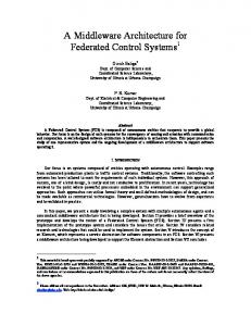
A. Synchronous data-flow The term synchronous resembles to the hypothesis of perfect synchrony described by Berry and Beneviste [13] and which is assumed for the temporal semantics of Lustre as well as for COLA. According to this hypothesis, the computation of the modeled tasks and communication between them happens infinitely fast. This allows for a discretization of the time base. Thus time is not any longer seen as a continuous value, but a progression of distinct ticks. Each of these ticks triggers the execution of the modeled tasks. And, as mentioned, these tasks are instantly computed and return their results. This procedure is repeated cyclicly during runtime. The time-triggered paradigm is well suited to realize such a periodic execution of tasks. This conforms to the model semantics as long as the call period is longer than the deadline specified for each task and data-dependencies are considered. The principles of an architecture for a time-triggered system have been introduced by Kopetz [14]. As the stated assumption of zero delay cannot be fulfilled by a real system, special care is required to approximate the model’s semantics as closely as possible. We will go into the details of this problem in Section IV. B. COLA We will exemplify our middleware approach using the modeling language COLA throughout this paper. A COLA model consists of software components communicating via directed communication links, called channels. The components are named units. In COLA several forms of units are defined (cf. [1]). Units of the types network and automaton may be decomposed hierarchically, that means, networks are made up of several sub-units connected via channels, and an automaton’s behavior in a certain state is implemented using a unit as well. Automata provide a form of control-flow to the COLA language. An automaton decides, depending on its input values, which state to activate. Hence only one of the units implementing its states can be active at a time. This characteristic of automata can be used to define the behavior of the system in a certain operating mode, for activation and deactivation of a system feature. Figure 1 shows a sample COLA automaton, which denotes that the two modes are changed each time the mode input signal, possibly generated by pushing a button, is set to 1. The feature referred to in the figure is a fictitious adaptive cruise control (ACC) which will be used as example throughout this paper. This device is intended to keep a car at constant speed, while maintaining a minimum distance to cars running ahead. Besides the mentioned modeling constructs, COLA uses basic arithmetic and logical operators, called functional blocks, for the implementation of the desired functionality. As stated before, a synchronous data-flow model is executed periodically. In order to buffer values from one invocation to the next, COLA provides a timing block called delay. A delay can store a single value for exactly one tick of the model time. Data are put into and out of the system using sources and sinks. These elements are the model representation of sensors
mode==1
DEV_S_ VIEW
c6
net_ui
c9
DEV_S_ TOUCH
net_acc_on
c5
net_acc_off
DEV_A_ DISPLAY DEV_S_ PRGM
c10
net_ACC_on_off
c4
mode==1
c12
DEV_S_ ROTATION
c11 c3
Figure 1.
COLA mode automaton for an ACC
net_rotation
c8
DEV_S_ SYSTIME
c2 DEV_S_ ULTRA
net_radar
c7
c1
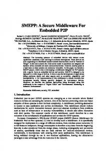
and actuators of the system in question. As the actual state of automata as well as the values stored in delays have to be preserved, each unit containing these constructs is stateful. The storage of these values is realized by the presented middleware approach, as described in Section III-A. C. COLA clusters When the functional design of the COLA software model is finished, the units are sectioned into distinct groups. These groups are called clusters and form the model representation of an executable task. Thus each cluster is transformed into one file of C-Code during code generation, as described by Haberl et al. [15]. When defining clusters on a hierarchy level lower than the system’s top-level unit, the clusters’ parent unit(s) lack the mapping to a software task. In order to cover the functionality of these parent units, they are inserted into one or more so called mode cluster. All other clusters are referred to as working clusters. The mode cluster’s job is to decide on which mode, and thus which working clusters, shall be executed. An example for such a clustering is given in Figure 2. The figure shows the top-level network of the ACC example to be sectioned into twelve clusters. While the clusters c1 through c11 are working clusters, c12 is intended to be a mode cluster. It is implemented by the automaton shown in Figure 1. The units implementing the automaton’s states are two additional working clusters. We will show some examples of the code generated for the ACC example in Section V-A. For a clustering to be valid, all units must be contained in a cluster and each mode cluster must consist of COLA automata exclusively. In a COLA model, units exchange data using channels. The inter-cluster communication is also given by these channels. Each channel which connects units mapped to different clusters, implies a need for communication between these clusters. This holds for all channels, that is the edges connecting the clusters, depicted in Figure 2. It is one of the tasks of the middleware to enable for this communication. III. M IDDLEWARE FUNCTIONALITY We will give a short introduction into the middleware’s functionality in this section. For detailed information about the realization of the described concepts see Section V-A.
DEV_A_ MOTOR
Figure 2.
A possible clustering for the ACC example
A. Local and remote communication A basic function of each middleware is the provision of communication mechanisms. For a clustered COLA model this includes inter-cluster communication. The border lines separating clusters are crossed by communication channels. Each such channel indicates a need for data exchange at runtime. This is one of the duties of our middleware. Every channel is assigned a virtual address, which is inserted into the appropriate middleware read and write calls during code generation. The middleware distinguishes between local and remote communication, according to the placement of sender and receiver. This information is taken from the configuration data generated for each node. Besides enabling for communication between tasks, the middleware also provides data keeping for each stateful task. Synchronous modeling languages assume tasks to be executed periodically. In COLA tasks containing either a delay or an automaton are stateful. This state is kept by the middleware between the periodic invocations of the task. The needed middleware API calls are, again, inserted during code generation. B. Operation modes As mentioned before, COLA allows for the definition of operating modes. Each mode cluster triggers a set of clusters, which we call working cluster, to be executed. During code generation all clusters are transformed into executable tasks. Hence, the activation of a mode, and all of its sub-modes, is calculated by a task as well. We call such a task a mode-task. Like all working tasks, mode-tasks have to be executed and consequently use the communication abilities of the middleware. Compared to working tasks, mode-tasks do not write any actuators directly, but calculate a value, which indicates their decision on the mode to be activated. As the middleware is the first instance to know about the result of the mode-task, it is responsible for calling all working tasks activated by that mode. This minimizes the delay between the decision on the active mode and the execution of the first working task.
C. Hardware interaction In COLA several channels can be connected to a single output of a unit. If this unit is a source this indicates the value of a sensor to be used by two different software components. Following the synchronous semantics of COLA, both software components have to be provided with the same value. Additionally the hypothesis of perfect synchrony assumes the complete system to be executed in virtually no time. Thus if several sources are read or actuators are written, semantics claim this to happen instantly. If hardware would be accessed directly by each task, this requirement couldn’t be fulfilled, as tasks have to be executed sequentially on each node of the system. To approximate the model semantics as closely as possible, we chose to realize hardware interaction via the middleware. As the middleware uses a last value semantics, sensor values can be read several times by different tasks. Each task will then read the same value. By running all sensor reads at the begin and all actuator reads at the end of each scheduling cycle, the moments of reading or writing the values are as closely synced as possible. Figure 3 shows this invocation of sensors, tasks and actuators during a scheduling cycle.
middleware running
applications running
middleware running
read sensors
COLA tasks
write actuators
scheduling cycle
Figure 3.
Hardware interaction
D. Global time The realization of a time-triggered system relies on the availability of a global time, as described by Kopetz [16]. This global time is used to start computation and communication on the different nodes according to a globally defined schedule. Our middleware API contains a function providing access to the global time. This function can be used by the node local dispatcher to initiate execution of the different tasks. IV. R EAL - TIME ENVIRONMENT The middleware is designed to offer communication services for distributed hard real-time systems. Such a real-time system consists of several processing units equipped with a processor, memory, a communication interface, and interfaces to interact with the environment. A unit with its dedicated hardware is called a node of the real-time system. On each node several tasks can be executed. The interaction of local and remote tasks realizes the functionality of the system. In a real-time environment it is essential that tasks finish execution within time, otherwise the produced results could be useless or even lead to failure. Tasks compete for limited computational resources provided by a node, but because of the a priori knowledge of task periodicities, time static scheduling can be employed to meet deadlines.
A. Communication network Bus access to the communication network connecting the nodes of the system is controlled using a time division multiple access (TDMA) strategy. That means, access to the network is divided into time slots. In each time slot only one node is allowed to send data, all others may receive data during that time. All slots together define the TDMA cycle. Figure 4 shows such a cycle, divided into five slots. Each node can be assigned multiple slots, one for each task it executes. An example for this is shown in Figure 4 where two slots are reserved for node 0. The TDMA cycle is repeated periodically and should be chosen as long as it takes for the slowest node to finish execution of all tasks. This allows for the definition of a system wide scheduling cycle. Tasks which have to be executed more frequently can be involved several times during each cycle. TDMA cycle
Slot 0
Node 0 Task 0
Slot 1
Slot 2
Slot 3
Slot 4
Node 0 Task 1
Figure 4.
Node 2 Task 0
TDMA scheme
Two approaches for allocating time slots can be thought of. One possibility is that each node in the system is assigned one time slot in each TDMA cycle, in which the node is allowed to send data. The length of that time slot either depends on how much data has to be sent by that node or the available amount of time is simply divided by the number of communication nodes. Another approach of distributing slots would be to assign a time slot to every task. This leads of course to more slots in a cycle and a longer cycle time, but the delay between finishing a task execution and distributing the produced data can be shortened. Therefore task scheduling and TDMA time slots have to be aligned to minimize distribution delay, shown in Figure 5. For our middleware the latter option of assigning slots to tasks rather than to nodes is chosen due to it’s greater flexibility in generating schedules and advantages considering delay. A protocol entitled Time Triggered Protocol (TTP) and similar to the TDMA scheme used for our middleware has been proposed by Kopetz [17]. Compared to the middleware presented here, the TTP assigns TDMA slots to nodes, not applications. In addition, the number of operating modes used in a system running the TTP is limited to eight instances. The approach presented here doesn’t limit the number of modes (neglecting the fact, that the number of logical addresses is limited by the chosen data type).
delay
task 1 execution time task 1 TDMA slot
Figure 5.
about a half cycle time. Task 4 has to wait in either case, because the slots passing at execution time belong to node 2. Note that TDMA slots cannot be shared between nodes. Each node that has to send event-triggered messages has to be provided with an own event-triggered time slot. If no eventtriggered communication occurs, these slots lie idle.
Delay between task termination and data distribution
V. O PERATION B. Time-triggered / event-triggered messages There are two established approaches in real-time systems design, namely the time-triggered and the event-triggered one. A time-triggered real-time system initiates actions like sending messages by the progression of time. The points in time when some action has to be carried out are defined offline and take place periodically. Event-triggered systems on the other hand do not have such static schedules. They observe the environment and actions are triggered by the occurrence of some special event. Therefore event-triggered systems require dynamic scheduling because the event occurrences cannot be known a priori. Primarily the middleware is designed to handle time-triggered messages. These periodic messages occur in every cycle, their size is known a priory. So enough time in the TDMA cycle can be reserved to ensure successful transmission. For the deployment of COLA models a time-triggered approach is preferred, as the perfect synchrony assumption implies the periodic invocation of all tasks in the system at discrete points in time. This matches the time-triggered paradigm well, which is also based on the cyclic activation of tasks. But in some cases it may also be convenient to send a message because of a special event, for example to realize some monitoring in case of errors. The occurrence of such a message is exceptional, so the message is not assigned a designated time slot. In order to allow a limited number of such event-triggered messages, an extra default time slot for each node is defined. All messages that are not planned a priori, and hence do not have a time slot assigned, are sent in this event-triggered slot. TDMA cycle ET slot 1 task 1
slot 1 slot 2 slot 3 task 2
task 1
ET slot 2
task 3
slot 5 slot 6 task 4
task 2
TDMA slots tasks node 1
OF THE MIDDLEWARE
For transmitting data the middleware does not rely on bus addresses of sender or receiver node. Instead every datum is assigned a unique numerical identifier used as its logical address. When a datum has to be transmitted to other nodes, it is passed to the middleware in combination with its logical address. Using this identifier, the middleware can determine which TDMA time slot has to be used for sending. As the TDMA cycle reaches the determined time slot, the datum with its identifier is broadcasted over the network. The receiving nodes store the received datum with the identifier as its key. Already existing data with the same key are replaced with the received data. Tasks on the receiving nodes are now able to retrieve the datum from the middleware by passing the identifier. The configuration for each node’s middleware instance is achieved by reading a configuration file during start-up. node 1
node 2
task 1
task 2
task 5
task 6
send ID42
receive ID42
receive ID42
receive ID42
Middleware
Middleware
broadcast ID42
receive broadcast Network
Figure 7.
Send and receive data using the middleware
The scheme of two nodes communicating is shown in Figure 7. Task 1 on node 1 sends data with identifier 42. The data is stored in the middleware, task 2 on the same node has immediate access. After the broadcast (which might be some time later), the tasks on node 2 also have access to the data sent by task 1.
tasks node 2
A. Middleware API Figure 6.
Scheduling of tasks on different node
Figure 6 presents an example how slots and tasks could be aligned. In the shown case time-triggered messages of task 1 would be delayed until the cycle reaches slot 1, but eventtriggered messages could be delivered immediately. On the other hand, time-triggered messages of task 3 can be sent contemporary, event-triggered messages would have to wait
To achieve a small and simple API, the middleware only provides the basic functions mw_send() and mw_receive(). The data to send or receive is identified by the logical address passed to the function as first argument. The second argument is a pointer to a variable the data are read from or written to. An example for the application of these calls is shown in Listing 1, which depicts the code for working cluster c8 of Figure 2. In lines 6 and 7 of the listing
the two input channels are read, while the result is written to the output channel in line 10. Reading and storing a tasks state is realized by using the calls mw_restore_task_state() and mw_save_task_state(). The usage of these calls is shown in lines 5 and 11 in the listing. The functions’ arguments are identical to those of mw_send() and mw_receive(). 1 2 3 4 5 6 7 8 9 10 11 12
void net_rotation200399() { state_rotation200399 unit_state; int rotation_0, time_1, rotation_out_0; mw_restore_task_state(7, &unit_state); mw_read(16, &rotation_0); mw_read(17, &time_1); rotation_out_0 = ((rotation_0 * 425) / (time_1 - unit_state.delay200513)); unit_state.delay200513 = time_1; mw_write(22, &rotation_out_0); mw_save_task_state(7, &unit_state); }
Listing 1.
Code for net_rotation.
B. Middleware configuration The middleware can be configured using a file. It contains an element hierarchy of nodes, tasks and data. Data identifiers can be defined and assigned to the tasks they belong to, tasks are sub-elements of nodes. TDMA slots can be assigned at task level, i.e. all data belonging to one task will be sent in the slot assigned to that task. Further, sensors and actuators are assigned to nodes so that the middleware can perform hardware access on the proper node. Sensor and actuator elements are like data elements with some hardware specific information, i.e. they also have identifiers for send / receive operations. Additionally a TDMA slot has to be assigned to hardware devices for sending values, because they operate independent of tasks as shown in Figure 3. With this configuration information, the middleware is able to allocate buffer space during startup phase, initialize sensor and actuator hardware for operation, and distinguish between local and remote communication. C. Sensors and actuators Since a real-time system often has to interact with the real world, there is a need to connect the tasks with sensor and actuator devices. These devices can be attached to any node in the system. The middleware provides functionality for transparent handling of remote devices to all nodes. Therefore sensor data is presented to the task like all other data, as described in the previous section. That means every sensor is assigned a unique identifier, the middleware is in charge of polling the sensor in an appropriate cycle time and storing the result with the identifier as a key. To make the data available for remote nodes the distribution mechanism for data is used. Writing data to actuator devices works similar. Data are stored in the middleware and distributed. When the node with the actuator device attached has to write a new value, it looks up the data for the identifier associated with the actuator device and writes it to the device. Sensor and actuator interaction is completely handled by the middleware, tasks just have to use the middleware’s mw_send() and mw_receive() API functions to write and read values.
As hardware device interaction is handled by the middleware and not by tasks directly, there has to be a scheme when interaction takes place, described in Figure 3. At the beginning of a cycle the middleware first reads sensor devices at a defined frequency. This means a sensor could be read every n-th cycle, in all other cycles the last value read will be used. After sensor values have been read and distributed, they are available to all tasks on all nodes. In the end of the cycle, when all tasks finished execution and all data are replicated to all nodes, each node with an actuator connected looks for data with the ID of the actuator in the buffer and writes that value to the hardware. D. Global time The employed TDMA bus protocol is realized using a global time base. According to this global clock, each node can determine the start of the slot assigned to it, as well as the points in time data sent by other nodes in the system have to be received. To achieve this, the protocol uses a clock synchronization mechanism to maintain a consistent view on the global time on each node. For a time-triggered system, the dispatching of tasks is also based on a global schedule. The middleware provides access to the global time maintained by the bus protocol, featuring the mw_global_time() call. E. Prototypical implementation A prototype realizing the described functionality has been implemented to show the viability of the described concepts. It is based on the RTnet protocol developed by Kiszka et al. [18]. RTnet is based on the real-time operating system Xenomai1, which comes as a patch for Linux systems, providing real-time capabilities for the modified system. The Xenomai dispatcher is charged with the execution of the middleware during the hardware interaction phase, as well as the execution of the application tasks. RTnet provides a TDMA scheme analog to the one described in Section IV-A. In order to accomplish the TDMA, a clock synchronization mechanism is included in RTnet. Our middleware uses this available time source as global time for the system. The TDMA schedule for RTnet is constructed according to the needs of the modeled software. As a lot of embedded systems rely on the use of a bus rather then a switched network, we use broadcast messages exclusively. During our tests the prototype showed the desired behavior, regarding timely sending and reception of messages, as well as storage of task states. For ease of testing, the configuration file is currently coded in XML. To conserve the short resources of an embedded system the file will be coded more efficiently in a future version. Unfortunately RTnet is not capable of changing the assignment of communication slots to nodes at runtime in its current version. This function would be desirable in case of a mode change of the system. It is subject to our current work to find a solution for this shortcoming. 1 www.xenomai.org
VI. C ONCLUSION In this paper we presented a middleware approach for use in distributed embedded real-time systems. Compared to existing alternatives, this middleware produces very few overhead but at the same time provides flexibility to the applications using it. The defined API is well suited to be used in unattended code generation and system configuration based on data-flow models. The semantics of COLA are preserved during this step, due to the time triggered scheme of the middleware. It is subject to our current work to add a possibility for modifying the TDMA slot to node assignment during runtime. This would ease the calculation of feasible system schedules as there would be no need to find a TDMA slotting valid for all possible modes of the system. Further we intend to extend the middleware’s functionality to make error tracing possible. By using the event triggered messages described in this paper, a possibility for distributing notifications about a change in system state, without influencing the system’s functionality, is given. Producing system monitors during code generation, which use the concept of the event triggered slots will be one of the next steps. R EFERENCES [1] S. Kugele, M. Tautschnig, A. Bauer, C. Schallhart, S. Merenda, W. Haberl, C. K¨uhnel, F. M¨uller, Z. Wang, D. Wild, S. Rittmann, and M. Wechs, “COLA – The component language,” Tech. Rep. TUM-I0714, Institut f¨ur Informatik, Technische Universit¨at M¨unchen, Sept. 2007. [2] M. Broy, “The ’grand challenge’ in informatics: Engineering softwareintensive systems,” Computer, vol. 39, no. 10, pp. 72–80, 2006. [3] D. C. Schmidt and F. Kuhns, “An overview of the real-time corba specification,” Computer, vol. 33, no. 6, pp. 56–63, 2000. [4] A. D. McKinnon, K. E. Dorow, T. R. Damania, O. Haugan, W. E. Lawrence, D. E. Bakken, and J. C. Shovic, “A configurable middleware framework with multiple quality of service properties for small embedded systems,” in NCA ’03: Proceedings of the Second IEEE International Symposium on Network Computing and Applications, (Washington, DC, USA), p. 197, IEEE Computer Society, 2003.
[5] D. C. Schmidt, “Middleware for real-time and embedded systems,” Commun. ACM, vol. 45, no. 6, pp. 43–48, 2002. [6] V. Subramonian, “Middleware specialization for memory-constrained networked embedded systems,” 2004. [7] A. S. Gokhale, D. C. Schmidt, T. Lu, B. Natarajan, and N. Wang, “Cosmic: An mda generative tool for distributed real-time and embedded applications,” in Middleware Workshops, pp. 300–306, 2003. [8] The MathWorks Inc., Using Simulink, 2000. [9] P. Caspi, D. Pilaud, N. Halbwachs, and J. Plaice, “Lustre: A declarative language for programming synchronous systems.,” in POPL, pp. 178– 188, 1987. [10] F. Maraninchi and Y. R´emond, “Mode-automata: About modes and states for reactive systems,” in ESOP ’98: Proceedings of the 7th European Symposium on Programming, (London, UK), pp. 185–199, SpringerVerlag, 1998. [11] P. Caspi, A. Curic, A. Maignan, C. Sofronis, S. Tripakis, and P. Niebert, “From simulink to scade/lustre to tta: a layered approach for distributed embedded applications,” SIGPLAN Not., vol. 38, no. 7, pp. 153–162, 2003. [12] A. Bauer, M. Broy, J. Romberg, B. Sch¨atz, P. Braun, U. Freund, N. Mata, R. Sandner, and D. Ziegenbein, “AutoMoDe — Notations, Methods, and Tools for Model-Based Development of Automotive Software,” in Proceedings of the SAE 2005 World Congress, (Detroit, MI), Society of Automotive Engineers, April 2005. [13] A. Benveniste and G. Berry, “The synchronous approach to reactive and real-time systems,” in Readings in hardware/software co-design, pp. 147–159, Norwell, MA, USA: Kluwer Academic Publishers, 2002. [14] H. Kopetz, “The time-triggered architecture,” in ISORC ’98: Proceedings of the The 1st IEEE International Symposium on Object-Oriented Real-Time Distributed Computing, (Washington, DC, USA), p. 22, IEEE Computer Society, 1998. [15] W. Haberl, M. Tautschnig, and U. Baumgarten, “Running cola on embedded systems,” in Proceedings of the International MultiConference of Engineers and Computer Scientists (IMECS 2008), 2008. [16] H. Kopetz, Real-Time Systems: Design Principles for Distributed Embedded Applications. Kluwer Academic Publishers, 1997. [17] H. Kopetz and G. Gr¨unsteidl, “Ttp - a protocol for fault-tolerant realtime systems,” IEEE Computer, vol. 27, no. 1, pp. 14–23, 1994. [18] J. Kiszka, B. Wagner, Y. Zhang, and J. Broenink, “Rtnet - a flexible hard real-time networking framework,” in 10th IEEE International Conference on Emerging Technologies and Factory Automation, Catania, Italy, 2005.