LA-UR-08-06545, Material Science and Technology, accepted for publication
A MOBILE-AGENT BASED WIRELESS SENSING NETWORK FOR STRUCTURAL MONITORING APPLICATIONS Stuart G. Taylor1, Kevin M. Farinholt1, Eric B. Flynn2, Eloi Figueiredo1, David L. Mascarenas2, Erik A. Moro1, Gyuhae Park1,*, Michael D. Todd2, Charles R. Farrar1 1 The Engineering Institute, Los Alamos National Laboratory, Los Alamos, NM 87545, USA 2 Department of Structural Engineering Department, University of California San Diego, La Jolla, CA 92093, USA E-Mails:
[email protected],
[email protected],
[email protected],
[email protected],
[email protected],
[email protected],
[email protected],
[email protected] * Author to whom correspondence should be addressed; Tel.: +1-505-663-5335; Fax: +1-505663-5225
Abstract: A new wireless sensing network paradigm is presented for structural monitoring applications. In this approach, both power and data interrogation commands are conveyed via a mobile-agent that is sent to sensor nodes to perform intended interrogations, which can alleviate several limitations of the traditional sensing networks. Furthermore, the mobile-agent provides computation power to make near real-time assessments on the structural conditions. This paper will discuss such prototype systems, which are used to interrogate impedance-based sensors for structural health monitoring applications. Our wireless sensor node is specifically designed to accept various energy sources, including wireless energy transmission, and to be wirelessly triggered on an as-needed basis by the mobile-agent or other sensor nodes. The capabilities of this proposed sensing network paradigm are demonstrated in the laboratory and the field. Keywords: Structural Health Monitoring, Wireless Sensing Network, Wireless Energy Transmission, Impedance Method.
LA-UR-08-06545, Material Science and Technology, accepted for publication
2
1. Introduction Structural health monitoring (SHM) is the process of detecting damage in structures. The goal of SHM is to improve the safety and reliability of aerospace, civil, and mechanical infrastructure by detecting damage before it reaches a critical state. To achieve this goal, technology is being developed to replace qualitative visual inspection and time-based maintenance procedures with more quantifiable and automated damage assessment processes.
These processes are
implemented using both hardware and software with the intent of achieving more cost-effective condition-based maintenance. A more detailed general discussion of SHM can be found in [1].
The field of SHM is an integrated paradigm of networked sensing and actuation, data interrogation (signal processing and feature extraction), and statistical assessment (classification of damage existence, location, and/or type) that treats structural health assessments in a systematic way. An appropriate sensor network is always required as a first line of attack in observing the structural system behavior in such a way that suitable signal processing and damage-sensitive feature extraction on the measured data can be performed efficiently.
A specific topic that has not been extensively addressed in the SHM literature is the development of rigorous approaches to designing the data acquisition portion of SHM sensing system. To date, almost all such system designs are done somewhat in an ad hoc manner where the engineer picks a sensing system that is readily available and that they are familiar with, and then attempts to demonstrate that a specific type of damage can be detected with that system. In many cases, this approach has been shown to be ineffective and, as a result, researchers have begun to develop sensor networks suited for SHM. Based on this research, several sensor network paradigms for SHM have emerged.
This paper will first provide several sensor systems that have been used for SHM, along with a summary of their relative attributes and deficiencies. A new and hybrid wireless sensor network (WSN) paradigm, which has been investigated by the authors, is then presented. In this approach, both power and data interrogation commands are provided by a mobile-agent that is sent to
LA-UR-08-06545, Material Science and Technology, accepted for publication
3
sensor nodes, alleviating several limitations of the traditional sensing networks. The mobile agent is a physically mobile WSN member, providing additional processing and power delivery support, and it should not be confused with a type of autonomous software referred to by the same name, which is characterized by its autonomy, learning ability, and mobility. 2. Current Sensing Network Paradigms for SHM Applications The number of sensing systems available for SHM is enormous and these systems vary significantly depending upon the specific SHM activity. Two general types of SHM sensing systems are described below.
2.1 Sensor Arrays Directly Connected to Central Processing Hardware A wired network telemeters data and transfers power to the sensor over a direct wired connection from the transducer to the central data analysis facility, which may or may not be on-site. Because this is the most common approach used for SHM studies, there are a wide variety of such systems. They can range in cost and complexity from a single peak-strain sensor to a custom-designed systems with hundreds of data channels and numerous types of sensors, costing multiple millions of dollars, such as the sensing system deployed on the Tsing Ma bridge in Hong Kong[2].
The advantage of a wired system is the wide variety of commercially available off-the-shelf systems that can be used for this type of monitoring. However, such systems are often difficult to deploy in a retrofit mode because they usually require AC power, which is not always available. Also, these systems are one-point failure sensitive with individual wires as long as a few hundred meters. Furthermore, system wires and cables can account for over 75% of the installation for larger scale structures, such as long-span bridges [3], and experience with field-deployed systems has shown that the wires can be costly to maintain because of environmental degradation and damage.
2.2. Decentralized Processing with Hopping Protocol The integration of wireless communication technologies into SHM methods has been widely investigated in order to overcome the limitations of wired sensing networks [3, 4, 5, 6]. Wireless
LA-UR-08-06545, Material Science and Technology, accepted for publication
4
communication can remedy the cabling issues with the traditional monitoring system and significantly reduce the maintenance costs. Wireless communication protocols are now standardized with such protocols as IEEE 802.11 through 802.16, and data transfer rates are now approaching those of conventional wired networks. Sensing, telemetry, and computing can now be performed on a single chip, reducing costs and permitting economically viable high-density sensor networks.
However, there are several technical challenges and requirements for wireless network applications caused by uncertain and often harsh deployment environments, as well as dynamic configuration demands.
For example, the networks must be autonomously reconfigurable,
meaning that each node, after deployment, must detect, identify, and locate its neighbor nodes. Of course, planned networks eliminate this challenge, but reconfigurable ad hoc networks are more robust because they can update periodically as both the environment changes or as nodes fail. Because there is no planned connectivity in ad hoc networking, the software must provide this information as necessary. As individual nodes receive neighboring information, they must intelligently fuse it with local information. Data fusion algorithms must be able to identify, classify, and accept or reject data packets all within the constraints of limited energy resources. Finally, the network, depending on the application, may have to deal with issues such as data security and seamless communication between mobile and stationary network devices.
Another major consideration in deploying a dense wireless sensor array is the problem of providing power to the sensor nodes. This demand leads to consideration of information as a form of energy: obtaining information costs energy. In the absence of a direct power source, localized power generation technologies utilizing ambient energy harvesting may be used to power the instrumentation [7]. In this case, the amount of information desired must be carefully balanced with the amount of energy available. While there is tremendous research into the development of energy harvesting schemes for large-scale alternative sources such as wind turbines and solar cells, energy harvesting for embedded sensing systems is still in a development stage, and only a few prototypes exist for field-deployment.
LA-UR-08-06545, Material Science and Technology, accepted for publication
5
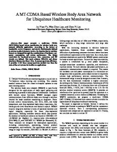
3. Mobile-Agent based Sensing Network Paradigm The sensing network paradigms described in the previous section have one characteristic in common. The sensing system and associated power sources are installed at fixed locations on the structural system. As stated, the deployment of such sensing systems can be costly and the power source may not always be available. A new and efficient future sensing network is currently being investigated by the authors [8,9] by integrating wireless energy transmission technology and remote interrogation platforms based on unmanned vehicles, such as a robot or an Unmanned Aerial Vehicle (UAV), to assess damage in structural systems. This sensing network is shown schematically in Figure 1. This approach involves using an unmanned mobile-agent node (delivered via UAV or robot) to generate a power-providing radio-frequency (RF) signal near receiving antennas connected to the sensor nodes that have been embedded on the structure. The sensors measure the desired response at critical areas on the structure and transmit the signal back to the mobile-agent again via the wireless communications. This wireless communications capability draws power from the RF energy transmitted between the host and sensor node and uses it to power the sensing circuit. Figure 1. A schematic of mobile-host based sensing networks.
LA-UR-08-06545, Material Science and Technology, accepted for publication
6
The mobile-agent paradigm also supports a hybrid WSN configuration, with multiple localized sensor networks within a single structure or application. This hybrid networking approach would be useful in situations where the data from one network could be used by the mobile-agent to identify which network it should proceed to interrogate, following critical or catastrophic events. This approach would enable the mobile-agent to bypass certain networks to interrogate those which have the most pertinent data for emergency response or security personnel, particularly in circumstances where speed of response is essential to saving human lives. It should be emphasized that this technology can be used in a hybrid configuration where the sensor node equipped with energy harvesting devices could be supplied supplemental energy by the mobile-agent. Even if the energy harvesting device provides sufficient power, the mobileagent can wirelessly trigger the sensor nodes, collect information and/or provide computational resources, significantly relaxing the power and computation demand at the sensor node level.
4. Sensor Node Design As this approach is a new sensing network paradigm, there is no off-the-shelf hardware readily available. Therefore, we developed wireless sensing hardware and associated sensors in this study. When designing these systems, particular attention was given to i) low-power operation, ii) wireless triggering capability, iii) wireless data transmission, and iv) interfacing with sensors with the required accuracy for SHM.
LA-UR-08-06545, Material Science and Technology, accepted for publication
7
The wireless impedance device (WID) developed at Los Alamos National Laboratory (LANL) is designed specifically to monitor the electrical impedance (and conversely the admittance) of piezoelectric (PZT) sensor using the Analog Devices AD5933 impedance chip. When bonded to a mechanical system, the electrical impedance of a PZT active sensor is directly coupled with the mechanical impedance of the structure. In SHM applications damage will manifest itself as a change or shift in the mechanical impedance of the system, which will then be reflected as a change in the electrical impedance of the piezoelectric sensor by the electromechanical coupling property of piezoelectric transducers [10]. This impedance method is utilized by the sensor nodes developed for this project. The AD5933 impedance chip is capable of resolving measurements up to 100 kHz, a frequency range that is ideal for many SHM applications. The WID is designed to offer a low-power option for active sensing, operating on 2.8 V and drawing only 56mW of power during measurement operations, and 61 mW during data transmission. These operations typically require 5-10 seconds, after which the WID can be placed in a sleep mode where power consumption drops below 30 µW. Several generations of the WID are shown in Figure 2, spanning from the first operational model WID1.5 to the most recent version WID3.0. Throughout the evolution of this hardware, several advancements have been introduced, including the ability to monitor up to seven PZT sensors per node, remote- and timer- based triggering options, as well as advanced telemetry components that have significantly reduced power needs. This hardware has been designed to operate with multiple power options, including the ability to store energy harvested from the environment or energy received through RF energy transmission. A more detailed description of this device can be found in the reference [11].
LA-UR-08-06545, Material Science and Technology, accepted for publication
8
Figure 2. First three generations of the WID developed at LANL and UCSD
WID 1.5 WID 3.0
WID 2.0
In addition to improving the capabilities and functionality of the previous WID versions, the WID 3.0 has been designed to function as part of a modular hardware platform consisting of both the WID and the Wireless Data Acquisition System (WiDAQ). The WiDAQ can function as a standalone device, and is controlled by an Atmel ATmega1281 microcontroller. The WiDAQ is shown in Figure 3. The WID 3.0 and the WiDAQ can share processing and data storage resources, and the WiDAQ utilizes the WID 3.0’s telemetry capabilities to create a wireless data acquisition system. The primary functions of the WiDAQ are data acquisition and signal generation. Sensor data can be acquired from any transducer that provides a voltage output using an Analog Devices AD7924 analog to digital converter. The four-channel AD7924 has a 12-bit resolution over a range from zero to 2.5 Volts, and it consumes a maximum of 6mW while sampling at one million times per second. The combined system with the ATmega1281 has a maximum useful sampling frequency of 40 kHz. The WiDAQ is designed for both passive and active sensing. In addition to the AD7924, an Analog Devices AD5621 D/A converter provides the excitation signal necessary for active sensing using piezoelectric patches. The AD5621 has a 12-bit resolution with an output range of zero to 2.5 Volts, consumes a maximum of 0.5 mW and is capable of driving a 2kΩ load in
LA-UR-08-06545, Material Science and Technology, accepted for publication
9
parallel with 1000 pF to ground. Each WiDAQ is capable of simultaneously providing an excitation signal through the AD5621 while measuring a response on each of the AD7924’s four channels. However, the maximum sampling frequency of 40 kHz must be shared between the A/D and D/A converters. In order to achieve the maximum frequency with active sensing, multiple WiDAQs could be used together. Figure 3. WiDAQ (left); Combined system of WID3 and WiDAQ (right)
5. Wireless Energy Transmission for Remote Powering Sensor Nodes 5.1 Background A major challenge impeding the deployment of wireless sensor networks is developing a means to supply power to the sensor nodes in an efficient manner. The authors have explored possible solutions to this challenge by using a mobile-host based wireless energy transmission system to provide energy (in addition to data interrogation commands and computing power) to sensor nodes. The mobile-agent features the capability of wirelessly transmitting energy to sensor nodes on an as-needed basis. In addition, it serves as a central data processing and repository center for the data collected from the sensing network. A pair of excellent survey articles were written to discuss the history of microwave power [12,13]. With the use of rectennas (antenna with a rectification circuit), efficiencies in the 50%80% range of DC to DC conversion was achieved. Significant testing has also been done across long distances and with kW power levels [14]. Their study showed the feasibility of the energy delivery systems to actuate large devices, including DC motors and piezoelectric actuators.
LA-UR-08-06545, Material Science and Technology, accepted for publication
10
However the application of this technology to low-power electronics has not been studied substantially in the past. In particular, the application of wireless power delivery for SHM sensor nodes in order to alleviate the challenges associated with power supply issues has never been addressed in the literature. The wirelessly transmitted microwave energy is captured by a receiving antenna, transformed into DC power by a rectifying circuit, and stored in a storage medium to provide the required energy for the sensor node. In the RF data or energy transmission application, there are five principal components: an RF signal source, an amplifier and/or attenuator conditioner, a transmitting antenna, a receiving antenna, and conditioning electronics to process the received signal. There are numerous geometries for the transmitting antenna, providing directional or omni-directional broadcast capabilities. For our application a directional antenna was most desirable, and work has been performed with both the parabolic grid reflector and the Yagi-type antennas. The typical gain for these antennas is on the order of 15-24 dBi for the 2.4 or 5.8 GHz Industrial, Scientific, and Medical (ISM) band. For the present study a commercially available 5.8 GHz parabolic grid antenna was used as the transmitting antenna. This frequency was chosen in order to avoid possible interference with the data communication in the 2.4 -2.5 GHz ISM band being used by the telemetry of the sensor node. In the design stage of this research, we focused on the development, fabrication and characterization of a microstrip patch antenna array that was designed to serve as our receiving antenna. To convert the received microwave energy into a DC signal the antenna is coupled with a rectifying circuit and a storage medium (typically a capacitor or battery) which collects the resultant energy. One of the limitations in microwave transmission is the attenuation of the wave as it travels through space. The loss associated with this attenuation has been characterized as the square of the distance between the transmitting and receiving antenna [15],as seen in the Friis transmission equation, PR =
GT G R λ 2 ( 4πR ) 2
PT ,
(1)
where GT and GR are the transmitting and receiving gains, λ is the microwave wavelength in meters, R is the distance between antennas in meters and PT and PR are the transmitted and received power in milliwatts.
LA-UR-08-06545, Material Science and Technology, accepted for publication
11
Figure 4. Thirty-two element, 5.8 GHz rectenna array designed at LANL
A microstrip patch antenna operates by creating a resonant cavity between a ground plane and a top plane of copper. The overall area occupied by the antenna is relatively small, on the order of 2.4 cm2. While the individual antenna has a low associated gain, large arrays of microstrip antennae can harvest much more of the incident wave generated by the source antenna. The output of each individual microstrip patch can be connected in a variety of ways to tune the amount of voltage harvested from the array. An example of a thirty-two element microstrip patch antenna array is shown in Figure 4. 5.2 Experimental Results Laboratory experiments were designed to evaluate the power efficiency of the prototype rectennas developed in this project, and to demonstrate that they could feasibly be used to power one of the low-power SHM sensor nodes. A reflector grid antenna was used as the source antenna, and was driven in the 5.8 GHz band through a RF signal source and a power amplifier. The output power was limited to 1 W for laboratory tests. The energy is received by the thirtytwo element rectenna array, located 0.6 m away. The experimental set-up used in the laboratory tests is shown in Figure 5.
LA-UR-08-06545, Material Science and Technology, accepted for publication
12
Testing was conducted to charge a 0.1 F capacitor to 3.5 V, which corresponds to the operating range of the WID sensor node. The voltage accumulation within the capacitor was monitored throughout the charging cycle, and the resulting charge time history is plotted in Figure 6. The result indicates that it takes approximately 40 seconds to charge the capacitor. These results compared favorably with the commercial panel antennas that were tested, which typically take at least a minute to charge the same supercapacitor. The sensor node is equipped with a power conditioning circuit that was designed to prevent the WID from being turned on until the voltage had reached 3.5 V. As the capacitor reaches the critical voltage of 3.5 V, the WID is powered on, measures the electrical impedance from two PZT sensors, and relays this data to a base-station located several meters away.
LA-UR-08-06545, Material Science and Technology, accepted for publication
13
Figure 5. Laboratory experiment designed to test the thirty-two element rectennas
Reflector Grid Antenna
32 rectenna Array
0.6 m
Wireless energy transmission has promise as a suitable solution for providing power to the proposed sensor node or any other (long-term) wireless sensor nodes. The advantage of this transmission system is that power does not have to be embedded with the sensing system, but transported to its vicinity and then wirelessly transmitted to the sensor node. It is anticipated that such a sensor network will have improved reliability and will have inherent advantages when monitoring must be performed in locations that are physically difficult to access. It is anticipated that these systems will evolve to hybrid systems that couple local energy harvesting at the node level with the RF energy delivered by the robotic vehicle. Figure 6. Laboratory results taken using the mobile-agent and the 32-patch array in close range to charge a 0.1 F capacitor.
LA-UR-08-06545, Material Science and Technology, accepted for publication
14
0.1 F Capacitor Charging Profile using 32 Patch Array 3.5
3
Voltage (V)
2.5
2
1.5
1
0.5
0 0
5
10
15
20 25 Time (s)
30
35
40
45
6. Mobile-Agent Design The mobile-agent used in this paper is a battery powered remote controlled (RC) vehicle. The vehicle weighs approximately 5 kg and carries the required components needed to implement the mobile-agent based SHM process. The computing source on the vehicle is provided by a laptop computer running a Windows XP operating system. This computer is remotely accessed from the base station, allowing command and control of the computer and RF source from the base station via 802.11g wireless network. The SHM software is installed on this computer to make a real-time assessment on the structural condition, which will be detailed in the next section. Data are received from the sensor node via an RS-232 enabled Meshnetics modem. The data are stored in the computer hard drive until requested by the base station. The vehicle can also wirelessly trigger the sensor node using a low frequency RF triggering antenna installed on the side of the vehicle. The triggering command is sent from the base station to the mobile computer, and the command is executed via an RS-232 connection, sending a wake-up 125 kHz RF wake-up signal to the sensor node.
LA-UR-08-06545, Material Science and Technology, accepted for publication
15
Figure 7. The mobile-host RC vehicle and its component 5.8 GHz reflector grid antenna for energy transmission
RF source and amplifier
Wireless camera with web server
Telemetry
Computation payload (laptop) Wireless triggering antenna
This vehicle also hosts a NovaSource G6 RF signal generator. This RF source signal is sent through a Stealth Microwave RF amplifier that increases the output power to levels that suitable for wireless power transmission (~1 Watt). Each of these components is also configured to be controlled remotely from the base station. For energy transmission, a parabolic grid antenna is mounted on the front of the vehicle. The mobile-agent also carries an Axis 207W wireless webcam for recording events as seen by the vehicle. The RF/Computational payload is powered
LA-UR-08-06545, Material Science and Technology, accepted for publication
16
by two separate Lithium-Polymer batteries. Figure 7 shows the various components on the vehicle. 7. Software Integration One major advantage of the mobile-agent paradigm is the ability to bring relatively high power and highly flexible computing to the sensor network for on-site SHM computations. The foundation of the software system is made up of self-contained, single-purpose blocks of code which we refer to as modules. At a base station server, the user assembles these modules to form SHM processes and then ports these processes to the roving host client for on-site execution. Here we describe in further detail each of these three primary elements. 7.1 Modules Each module is designed to perform a single, self contained task, and follows an established set of data formatting standards. The established data standards and a built-in flexibility within the modules eliminate the need for any intermediate code, allowing for rapid algorithm development. For this study, we developed a library of modules for data acquisition, feature extraction, feature classification, and report generation. 7.2 Base Station Server At the base station server, through a simple interface, modules are graphically assembled together and parameters are linked from one module to the next to form a linear sequence. A generic wrapper function, which manages the parameter passing, is built automatically from this arrangement and a set of links. After the sequence is constructed, the user can test the sequence and tweak user-defined inputs through simulation of the roving host environment. When the testing is complete and the desired input parameters are established, the server uploads the sequence and parameters to the roving host before it is released to the field. A snapshot of the module assembly process is shown in Figure 8. The automatic code generation of the sever, along with the flexible modules, allows for rapid prototyping, deployment, updating of an SHM process, and roving host turn around. Figure 8 A snapshot of the module assembly process in the base station. The assembled modules can be dynamically exported to a mobile station.
LA-UR-08-06545, Material Science and Technology, accepted for publication
17
7.3 Roving Host Client At the roving host client, the downloaded sequence is initiated by an external trigger. This trigger may be from the roving host’s navigation system, a remote user (if communication is possible), or the sensor node itself. The modules in the sequence then perform the tasks of establishing communication with the sensor nodes, requesting and receiving data from the nodes, processing the data to extract relevant features, classifying the data, and updating the classification model. Each module, in order, stores any relevant data to file and updates a single running html report, providing the results of its individual task. Upon the roving host’s return to the base station, the full report and all data files are uploaded to the base station server for viewing and possible further processing.
LA-UR-08-06545, Material Science and Technology, accepted for publication
18
8. Experimental Verification at the Alamosa Canyon Bridge The first field test of the proposed sensing network was performed on the Alamosa Canyon Bridge in the southern New Mexico, USA. The bridge is a traditional steel girder bridge with a reinforced concrete deck 25 cm thick. This bridge has been decommissioned and is utilized by the New Mexico State Department of Transportation as a test bed for structural health monitoring systems from university and research organizations. First, the wireless triggering capability of WID by a mobile-agent is shown in bolted joint monitoring of the bridge. Second, following the successful operation of the WID exclusively from RF energy as demonstrated in the laboratory, a series of field experiments were developed to further test the system’s performance under more rigorous operating conditions. Next, hybrid networking capabilities were demonstrated as the mobile-host as it traveled to different local networks to collect the data from each one. Finally, the capability of the combined WID and WiDAQ system to measure the low-frequency vibration data of the bridge under impact loading was demonstrated. Figure 9. Layout of the field test conducted at Alamosa Canyon Bridge, NM.
Sensor node4 Sensor node1
Sensor node2
Sensor node3
Mobile-agent
Eight sensor nodes were mounted along the longitudinal rail of the bridge. Four sensor nodes installed along the east side of the bridge are shown in Figure 9. The nodes were spaced at intervals of 5 meters. The sensor nodes were mounted on top of the deck for ease of access, and each sensor node was connected to three instrumented washers below the deck that were mounted using steel bolts (19 mm diameter) to secure a steel cross member to the outer girder of the bridge. A series of three instrumented washers is shown in Figure 10, with an exploded view
LA-UR-08-06545, Material Science and Technology, accepted for publication
19
of an individual washer clamped between the girder and the steel nut. The tightness of these components was varied throughout the experiment to test the sensor node’s ability to identify the state of each instrumented bolt mounted on the bridge. All the sensor nodes were configured to be wirelessly triggered by the low frequency RF signal, which would be initiated by the mobileagent vehicle. The operating principle of the PZT instrumented washer is described here. These washers are used in the same manner as their conventional counterparts. If these devices are mounted in a structure, the dynamics of these washers will be changed as the preload is changed. More specifically, the resonant peaks of the device would all shift to slightly higher frequencies, and then, at a certain threshold level of tightness, the magnitude of the peaks would drop substantially until the magnitude would almost disappear. These changes can be efficiently monitored by the impedance method and WID. More detailed discussion on this principle can be found in the reference [16]. Figure 10. Instrumented bolts mounted to the girder of the Alamosa Canyon Bridge. Preload was monitored with the PZT sensors using WID sensor nodes.
PZT sensor
LA-UR-08-06545, Material Science and Technology, accepted for publication
20
8.1 Wireless Triggering Test For this testing, the remotely controlled mobile-agent approaches the sensor node and establishes a range of 3 m between the RF triggering antenna installed on the side of the vehicle (shown in Figure 7) and the sensor node. The triggering command is sent from the base station, which monitors the movement of the vehicle through the wireless video camera mounted on the mobile-agent. The computer inside the vehicle receives this command and executes it by sending a 125 kHz RF wake-up signal to the sensor node. The sensor node is brought out of its sleep status by this signal, takes the measurements from the piezoelectric sensors, locally determines the magnitude of the resonance of each sensor, and broadcasts the data to the mobilehost vehicle. The laptop computer inside the RC vehicle receives and processes these data to make the decision on health-assessment conditions of each joint. The entire process is also passively monitored by the computer at the base station. The WIDs were programmed to monitor the peak magnitude of the washer in the frequency range of 51-53 kHz and, it was configured to be triggered by the low frequency signal. For the mobile-host, data are wirelessly received through the Zigbee RF telemetry module that was used as a serial port interface. Several software modules were written for importing and processing data from the serial port. For the first test, all the bolts connected to each sensor node were tightened to 240 in-lb of torque. The mobile-host vehicle then moves close to each sensor node, wirelessly triggers the nodes, and receives and processes the data. On the mobile-agent’s first passes through the sensor network, collected measurements were used to build and update a running probability density model. A snapshot of the report as generated by the mobile-host for the first interrogated node is shown in Figure 11. Each sensor shows three data points that correspond to results from three piezoelectric sensors connected to a node. Note that the outlier identification has no significance until a sufficient model has been built up. After the mobile-host made several passes through the network, damage was introduced by loosening one bolt (out of three) to hand-tightened for joints connected to the sensor nodes 7 and 8. Figure 11 also shows a snapshot of the report resulting from the interrogation of sensor node 7. The mobile-host reported a significant increase in the maximum impedance on the third bolt
LA-UR-08-06545, Material Science and Technology, accepted for publication
21
and correctly identified it as an outlier. The percentile is an estimate of the fraction of the number of measurements expected to have a higher local probability density than the current measurement based on the probability density model. Thresholds were chosen by the outlier model trainer to correspond with a 95% confidence level. Using this interrogation process, all damaged joints were identified with a 100% detection rate and 0% false alarm rate.
LA-UR-08-06545, Material Science and Technology, accepted for publication
22
Figure 11. Reports generated by the mobile-agent
No Damage Damage Identified
As shown in this example, using the mobile-agent, the structural health assessment can be made very quickly in an entirely wireless manner. This approach could alleviate several problems of traditional ad-hoc and hopping networks, such as data collision and communication failure in the node level [17]. Furthermore, this technology may be adapted and applied to damage detection in a variety of other civilian and defense-related structures such as, nuclear power plants where it is advantageous to minimize human exposure to hazardous environments during the inspection process.
LA-UR-08-06545, Material Science and Technology, accepted for publication
23
8.2 RF Energy Transmission For wireless energy transmission, three sensor nodes on the west side of the bridge were reconfigured to take measurements and transmit data once powered on by the wireless energy transmission system. For the WID3, a power conditioning circuit was implemented, which allows the capacitor to charge to a predefined voltage of 3.5V before sending power to the WID. The microstrip patch antenna array mounted near a sensor node is shown in Figure 12. Figure 12. Rectenna arrays used for powering WID at the bridge
Rectenna array 1
Rectenna array 2
Rectenna array 3
The energy transmission equipment was mounted within the mobile-agent vehicle as shown in Figure 7. The RF source was configured to emit 1W of energy at 5.8 GHz and was positioned to transmit over a distance of 0.5 m. This RF transmission system was also remotely operated by the driver of the vehicle from the base station, and the system was turned off once voltage was supplied to the sensor node. Multiple experiments were performed using this system as the vehicle was driven up to the rectenna where the vehicle was stopped and energy was beamed to the receiving antenna. The setup of this testing is shown in Figure 13.
LA-UR-08-06545, Material Science and Technology, accepted for publication
24
Figure 14 depicts the charging profile within the 0.1F supercapacitor as the RF energy was being transmitted. The system was capable of charging the capacitor to a voltage of 3.5V in an average time of 50 seconds at a distance of 0.5 – 0.7 meters. The plot indicates that it took about 10 seconds longer than the results obtained from the laboratory. The change in performance could be due to a less than ideal alignment between two antennas in the field. In this figure the wireless transmission was initiated at 2 seconds and approximately 50 seconds later, the power conditioning circuit is triggered, causing the sensor node to become active and take a measurement of the piezoelectric sensors, as indicated by the sharp drop in voltage at 52 seconds. The voltage then stabilizes as the microcontroller performs local computations, at which point the sensor node transmits the data to the mobile-agent as indicated by the sharp drops in voltage. Figure 13. Setup of RF transmission at the bridge.
0.6 m
LA-UR-08-06545, Material Science and Technology, accepted for publication
25
Figure 14. The results taken from using the mobile-agent and the 32-patch array to charge a WID sensor node at the bridge. 0.1 F Capacitor Charging Profile using 32 Patch Array at Bridge 3.5
3
Voltage (V)
2.5
2
1.5
1
0.5
0 0
10
20
30 Time (s)
40
50
60
This study provides an excellent opportunity to demonstrate the feasibility of the mobile-host based wireless sensor network. By using the wireless energy transmission, the sensor nodes do not have to carry on-board power sources, and the required energy can be delivered on an asneed basis. This technology will be directly applicable to rapid structural condition assessment of buildings and bridges after an earthquake where the sensor nodes may need to be deployed for decades during which conventional battery power would be depleted. 8.3 Local Network Association Test The local network association test simulates a permanent installation of WIDs for continuous automated monitoring of large-scale structures, using three separate local networks to demonstrate the hybrid networking capabilities of the WSN. The schematic of the local network is shown in left-hand image in Figure 15. Maintaining separate local networks has several advantages with very large structures in that additional routers to transmit data over large distances are not required. Furthermore, immediately following a catastrophic event, the loss of a single node could not destroy the entire network. This networking approach is more efficient
LA-UR-08-06545, Material Science and Technology, accepted for publication
26
with active-sensing SHM techniques, as those techniques are local area monitoring techniques, as opposed to global structural monitoring systems. Three separate local networks were implemented on the bridge, each operating using a different frequency band. Each coordinator was constantly powered, and the end devices operated in an extremely low-power mode, awakening at regular intervals to take measurements, and transmit the results to the coordinator. The coordinators stored received measurements on non-volatile until the data were retrieved by the mobile-agent. The setup of this testing on the bridge is shown in the right-hand image of Figure 15. Figure 15. (left) Separate local networks schematic; (right) Mobile-agent approaches coordinator A to retrieve data from network A.
Network A End Devices Network
Network
Coordinator C Coordinator B
Coordinator A Mobile-Agent
This local network approach is somewhat unique for SHM applications, as SHM sensors and sensor nodes do not have to be deployed on to the entire structure. Instead, the nodes could be installed on critical areas of a structure, following the concept of the active-sensing SHM strategy. The sensor node does not have to attempt to identify any neighbor nodes or relay the data, as in the case of the hopping networking protocol. Furthermore, the sensors can be more optimally placed on a structure to improve the performance of the SHM process. The authors are currently investigating the feasibility of using the mobile-agent as a “communication bridge.” Each local network operates as described above, and if needed, the mobile-agent executes a command to coordinators in the range to instantaneously construct a “global” network from each local network. In such a way, low-frequency global monitoring, as well as active, local monitoring could be readily performed.
LA-UR-08-06545, Material Science and Technology, accepted for publication
27
8.4 Low-frequency Vibration Acquisition Test Using WiDAQ The final testing was done by taking the low-frequency vibration data of the bridge using WiDAQ. Before the test, a traditional data acquisition system was used to measure the data for comparison purpose. The test procedure was essentially the same as the one performed previously [18], and briefly described below. The data acquisition system was set up to measure acceleration and force time histories and to calculate frequency response and coherence functions. Sampling parameters were specified that calculated the frequency response functions (FRFs) from a 16 second time window discretized with 2048 samples. The FRFs were calculated for a frequency range of 0-64 Hz at a frequency resolution of 0.0625 Hz. A PCB model 086B0 impact sledge hammer was used to provide the excitation source. The sensor in the hammer had a nominal sensitivity of 0.169 mV/N and a peak amplitude range of 22300 N. A specially designed hammer tip was used to broaden the time duration of the impact, and hence, better excite the low frequency response of the bridge. PCB model 336C piezoelectric accelerometers were used for vibration measurements. These accelerometers have a nominal sensitivity of 1 V/g, a specified frequency range of 1-2000 Hz, and an amplitude range of +/- 4g. All accelerometers were mounted to the bottom flange of the steel girders using PCB model 080A05 magnetic mounts. A total of 20 acceleration measurements were made on the girders below the bridge and at the excitation point, which was located on the top of the concrete deck. The experimental procedure, sensor locations, and the excitation point can be found in the reference [18].
LA-UR-08-06545, Material Science and Technology, accepted for publication
28
Figure 16. WiDAQ installed on the bridge girder to measure the response from accelerometers
WiDAQ Enclosure
Accelerometer
After performing the baseline modal test with a conventional wired system, six WiDAQs were installed in the structure. An installed WiDAQ with its enclosure is shown in Figure 16. Four PCB model 336C accelerometers were connected to each of five WiDAQs, for a total of 20 acceleration measurement channels. The PCB model 086B0 impact sledge hammer was connected to one input channel on the sixth WiDAQ. Specially designed ICP boards were used to condition the measurement data for the AD7924 A/D converter. An additional ZigBee device was used as a network coordinator to control measurement triggering, and to interface with a PC to collect the measured vibration data. Time synchronization is of particular importance with data acquired for modal analysis. To begin recording acceleration data, the network coordinator broadcasts a start signal to all network devices. Using a single-hop network, the coordinator is in direct communication with each WiDAQ, and each device begins recording data simultaneously. Each WiDAQ recorded a 20-second time record at a sampling frequency of 200 Hz for each of the four channels, utilizing local flash memory to store the recorded data. A total of eight impacts were given during this time record period. At the end of the time record, each WiDAQ transmitted their data in turn to the coordinator, which passed the data to a PC through the serial
LA-UR-08-06545, Material Science and Technology, accepted for publication
29
port. Figure 17 shows a segment of the input time history and the subsequent time response from one of the accelerometers recorded by WiDAQ. Figure 17. Time history excerpts recorded by a WiDAQ during the 20-second measurement. Hammer Input
Voltage
0.1 0.05 0 0
0.2
0.4
0.6
0.8
1
1.2
1
1.2
Time (sec) Accelerometer Response
Voltage
0.5
0
-0.5
0
0.2
0.4
0.6
0.8
Time (sec)
The frequency response function after processing the raw time domain data for the measurement shown in previous figures is shown in Figure 18. The FRF clearly shows resonant peaks near 8 and 12 Hz, roughly corresponding to the first and third vibration modes identified using a traditional modal test. One disadvantage of the WiDAQ system is that its resolution is limited by a 12-bit A/D converter, compared to the 24-bit resolution of the traditional data acquisition system. As a result, the normally low amplitude response of the bridge is not captured as clearly. The use of a high resolution (16bit) converter would improve the precision, but it would come with higher power consumption. This issue is currently being investigated by the authors.
LA-UR-08-06545, Material Science and Technology, accepted for publication
30
Figure 18. An FRF estimate of the raw time data measured by WiDAQ Accelerometer 16 Frequency Response
0
Magnitude
10
0
10
20
30 40 Frequency (Hz)
50
60
It should be noted that the use of the WiDAQ functionality is not fully integrated with the mobile-agent. However, as shown in the previous testing, it can be envisioned that the mobileagent could dynamically associate with the network, execute a command and collect data, and provide computational resources to process the data for the sensor node, while travelling through the network. For instance, the data processing of the previous example (calculating FRFs) could be done on the PC of the mobile-agent while it moves to the next sensor node and collects data. As shown in the results, we successfully demonstrated that our sensor node is capable of measuring the low-frequency data, those typically used in modal analysis. The A/D chip used in the WiDAQ can be configured to interact with many different sensors, making our sensor node a versatile platform that could be used in numerous sensing applications. 9. Summary and Conclusions In this paper, the current research in developing a mobile-agent based sensing network paradigm is presented. This paradigm is designed to overcome the limitation of the existing sensing
LA-UR-08-06545, Material Science and Technology, accepted for publication
31
network for various sensing network applications. In particular, a series of the wireless sensor nodes designed for inclusion in a mobile-host wireless sensor network has been described for structural health monitoring applications. The wireless impedance device, which capitalizes on the well-established impedance-based structural health monitoring technique, was developed to monitor the conditions of a structure. The sensor node requires very low-power and is capable of being wirelessly triggered by a mobile-agent for use in the proposed mobile-host based wireless sensing network. The mobile-agent is equipped with the capability to dynamically associate with any local network to perform intended operations. Furthermore, the node is capable of collecting low-frequency vibrational data for various applications. Wireless energy transmission offers an alternative method for powering wireless sensor nodes in SHM or other engineering applications and demonstrated the effectiveness in this paper. The advantage of RF energy transmission is that it augments or removes the need to have a conventional power source embedded within the structure with each sensor node. The performance of these devices is first verified in the laboratory. Subsequent field tests demonstrate that these sensor nodes can efficiently monitor several mechanical response parameters suitable for rapid assessment of structural conditions. 10 Acknowledgements The authors would like to thank the New Mexico Department of Transportation for their help in conducting experiments on the Alamosa Canyon Bridge in southern New Mexico. 11 REFERENCES 1. Worden, K. and J. M. Dulieu-Barton (2004) “An Overview of Intelligent Fault Detection in Systems and Structures,” Int. J. of Structural Health Monitoring, 3 (1) pp. 85–98. 2. Ni YQ, Wang BS, Ko JM. (2001) “Simulation studies of damage location in Tsing Ma Bridge deck,” Proc., Nondestructive Evaluation of Highways, Utilities, and Pipelines IV, SPIE, Bellingham, Wash., 312–323. 3. J.P. Lynch, and K. J. Loh, (2006) “A summary review of wireless sensors and sensor networks for structural health monitoring,” The Shock and Vibration Digest, 38(2), pp. 91–128. 4. Jia, Y. Sun, K. Agosto, F.J., Quiñones, M.T. (2006) “Design and characterization of a passive wireless strain sensor,” Meas. Sci. Technol. 17 No 11, 2869-2876. 5. Collett, M.A., Cox, M.G., Duta, M., Esward, T.J., Harris, P.M., Henry, M.P., (2008) “The application of self-validation to wireless sensor networks,” Meas. Sci. Technol. 19 No 12 125201.
LA-UR-08-06545, Material Science and Technology, accepted for publication
32
6. Kuang, X., Feng, R., Shao, H., (2008) “A lightweight target-tracking scheme using wireless sensor network,” Meas. Sci. Technol. 19 No 2, 025104. 7. Park, G., Farrar, C.R., Todd, M.D., Hodgkiss, W., Rosing, T., (2008) “Energy Harvesting for Structural Health Monitoring Sensor Networks,” ASCE Journal of Infrastructure systems, Vol. 14, No.1, pp. 64-79. 8. Farrar, C.R., Park, G., Allen, D.W., Todd, M.D., (2006) “Sensor Network Paradigms for Structural Health Monitoring,” Structural Control and Health Monitoring, Vol. 13, No. 1, pp. 210-225. 9. Todd, M.D., et al., (2007) “A Different Approach to Sensor Networking for SHM: Remote Powering and Interrogation with Unmanned Arial Vehicles,” Proceedings of 6th International Workshop on Structural Health Monitoring, September 11-13, Stanford, CA. 10. Park G., Sohn H., Farrar C.R., Inman D.J. (2003) “Overview of Piezoelectric ImpedanceBased Health Monitoring and Path Forward,” Shock and Vibration Digest, 35, 451-463 11 . Overly, T.G., Park, G., Farinholt, K.M., Farrar, C.R. (2008) “Development of New Generation of Impedance-based Wireless Sensing Device,” Smart Materials and Structures, Vol. 17, No. 6, pp. 065011. 12. Brown, W.C. (1996) “The History of Wireless Power Transmission,” Solar Energy, Vol. 56, No. 1, pp. 3-21. 13 . Maryniak, G.E. (1996) “Status of International Experimentation in Wireless Power transmission,” Solar Energy, Vol. 56, No. 1, pp. 87-91 14. Choi, S., Song, K., Golembiewskii, W., Chu, S.H., King, G. (2004) “Microwave Power for smart material actuators,” Smart Materials and Structures, Vol. 13, pp. 38-48 15. Pozar, D., (2005) Microwave Engineering, Third Edition, John Wiley and Sons, 647-648. 16. Mascarenas, D.L. Park, G., Farinholt, K.M., Todd, M.D., Farrar, C.R., (2008) “Remote Inspection of Bolted Joints using Piezoelectric Active-Sensors,” The Institution of Mechanical Engineers, Part G: Journal of Aerospace Engineering, accepted for publication. 17. Dove J.R., Park, G., Farrar, C.R., (2006) “Hardware Design of Hierarchal Active-Sensing Networks for Structural Health Monitoring,” Smart Materials and Structures, Vol. 15, No. 1, pp. 139-146. 18 . Farrar, C.R., Cornewell, P.J., Doebling, S.W., Prime, M.B. (2000) Structural Health Monitoring Studies of the Alamosa Canyon and I-40 Bridges, Los Alamos National Laboratory Report, LA-13635-MS.