A model of echolocation of multiple targets in 3D space from a single emissiona) Ikuo Matsuob) Research Institute of Electrical Communication, Tohoku University, Katahira 2-1-1, Aoba-ku, Sendai 980-8577, Japan
Junji Tani Institute of Fluid Science, Tohoku University, Katahira 2-1-1, Aoba-ku, Sendai 980-8577, Japan
Masafumi Yano Research Institute of Electrical Communication, Tohoku University, Katahira 2-1-1, Aoba-ku, Sendai 980-8577, Japan
共Received 29 November 2000; revised 2 April 2001; accepted 9 April 2001兲 Bats, using frequency-modulated echolocation sounds, can capture a moving target in real 3D space. The process by which they are able to accomplish this, however, is not completely understood. This work offers and analyzes a model for description of one mechanism that may play a role in the echolocation process of real bats. This mechanism allows for the localization of targets in 3D space from the echoes produced by a single emission. It is impossible to locate multiple targets in 3D space by using only the delay time between an emission and the resulting echoes received at two points 共i.e., two ears兲. To locate multiple targets in 3D space requires directional information for each target. The frequency of the spectral notch, which is the frequency corresponding to the minimum of the external ear’s transfer function, provides a crucial cue for directional localization. The spectrum of the echoes from nearly equidistant targets includes spectral components of both the interference between the echoes and the interference resulting from the physical process of reception at the external ear. Thus, in order to extract the spectral component associated with the external ear, this component must first be distinguished from the spectral components associated with the interference of echoes from nearly equidistant targets. In the model presented, a computation that consists of the deconvolution of the spectrum is used to extract the external-ear-dependent component in the time domain. This model describes one mechanism that can be used to locate multiple targets in 3D space. © 2001 Acoustical Society of America. 关DOI: 10.1121/1.1377294兴 PACS numbers: 43.80.Lb, 43.64.Bt, 43.80.Jz 关WA兴
I. INTRODUCTION
Bats have the special ability to form an image of the world based on acoustic information, while most animals form images of the world that are more strongly based on visual information. They emit trains of high-frequency sounds and can locate an individual target among multiple objects by using the echoes of these emissions that overlap in time 共Griffin, 1958; Simmons et al., 1995a兲. In order to recognize objects in three-dimensional 共3D兲 space, bats need to process the information that the echoes contain to determine the distance and direction to each object. With regard to the determination of distance, it has been found in physiological studies that delay-tuned neurons in the central auditory system are capable of determining the interval between an emitted sound and the returning echo 共Dear et al., 1993a, b; Kawasaki et al., 1988; Schuller et al., 1991; Suga, 1984; Suga et al., 1978; Sullivan, 1982兲. In a case of interfering echoes, responses of neurons in the inferior colliculus 共IC兲 depend on the amplitude change based on a兲
A portion of this work has been presented at the WESTPRAC, Kumamoto, Japan, October 2000. Electronic mail:
[email protected]
b兲
J. Acoust. Soc. Am. 110 (1), July 2001
the interference between echoes 共Sanderson and Simmons, 2000兲. There might be the mechanism that a bat uses to determine a target’s distance. There are a number of existing behavioral experiments involving bats and their determination of distances to objects. The results of these experiments regarding the resolution with which bats are capable of determining these distances vary greatly, depending on the specific conditions of the experiments. When two different targets are presented, either simultaneously or sequentially on either side of the animal, the accuracy of the determination of the difference in distance to the two objects is about 1–2 cm, corresponding to a time resolution of about 50–100 s 共Simmons, 1973; Miller, 1991; Surlykke, 1992兲. Contrastingly, when two phantom targets, one of which emits ‘‘phantom echoes’’ at times which follow the bat’s emissions after a fixed interval and one of which emits ‘‘phantom echoes’’ at times which follow the bat’s emissions after intervals whose lengths fluctuate about some average value 共a ‘‘jitter condition’’兲, are presented, bats can distinguish objects separated by distances of well under 1 mm 共Simmons et al., 1990a兲. In such distance discrimination experiments, it has been clearly demonstrated that a bat can accurately distinguish minute variations
0001-4966/2001/110(1)/607/18/$18.00
© 2001 Acoustical Society of America
607
in the arrival times of echoes from simple targets with single reflecting surfaces, although the mechanism allowing this incredible spatial resolution is not yet well understood. Bats distinguish the arrival times of echoes from objects that are positioned at nearly equal distances 共Simmons, 1989; Simmons et al., 1990b兲. The echoes from objects whose distances from a bat are sufficiently close, termed ‘‘nearly equidistant objects,’’ will overlap and interfere with each other, so that the arrival time corresponding to the more distant target cannot be directly determined from the detection of returning echoes. It thus may be inferred from a bat’s ability to discriminate two closely situated targets that they locate each target by utilizing spectral information produced by the interference of the echoes from the two targets. However, there remains the important problem of determining how the bat can determine the correspondence between echoes and targets among those received from multiple and nearly equidistant targets. Bats are able to discriminate the direction of an echo’s source to within 1.5°–3.0° 共Lawrence and Simmons, 1982; Simmons et al., 1983兲. Binaural cues used for directional localization are the interaural time difference 共ITD兲 and interaural intensity difference 共IID兲. In most animals, neurons in the medial superior olive 共MSO兲 within the superior olive complex have been found to respond to the ITD 共Pickles, 1988兲. However, neurons in the MSO of echolocating bats are neither significately excited nor inhibited by input through the ipsilateral ear 共Covey and Casseday, 1991; Grothe et al., 1992兲. This suggests that the ITD is not a crucial cue in horizontal localization for bats. Another possibility as a useful cue in horizontal localization is the IID. In fact, there are IID sensitive neurons in the lateral superior olive 共LSO兲 of bats, which are excited by input through the ipsilateral ear and inhibited by input through the contralateral ear 共Casseday et al., 1988; Covey and Casseday, 1991兲. Moreover, neurons in the superior colliculus 共SC兲 and auditory cortex 共AC兲 exhibit directional sensitivity 共Jen et al., 1984, 1989; Valentine and Moss, 1997兲. However, it remains unclear how bats actually use these cues for the localization of targets. The localization of targets in 3D space has been extensively investigated in computational studies. A binaural model was proposed by Altes 共1978兲 to determine the distance and the direction of a single target using an idealized directivity pattern generated by emission from the mouth and reception at the ears. This model contains a set of arbitrarily chosen frequency spectral pattern templates, one corresponding to each direction 共Altes, 1978兲. In this model, the distance and direction to a target can be determined from the return time and by comparing the composite echo with the template set, respectively. In order to avoid the necessity for comparison between an echo and the elements of the template set one by one, Kuc 共1994兲 simplified this model by introducing an emission consisting of a fundamental frequency and two overtone components. In this case, if the dependence of the reception at two ears for the two overtone components on the direction of the emission and from the mouth is given, the azimuthal direction and the elevational direction can be determined from the IID and the interfre608
J. Acoust. Soc. Am., Vol. 110, No. 1, July 2001
quency intensity difference 共IFID兲 共Kuc, 1994兲. These two binaural models are useful only for a single target, because the returning echoes from multiple targets usually interfere with each other to produce a spectrum that is too complex to identify the direction of any single target. In order to distinguish multiple targets, in particular two targets closely located on a one-dimensional range axis, Saillant et al. 共1993兲 proposed a monaural model referred to as the SCAT 共spectrogram correlation and transformation兲 model. In this model, the returning composite of an echo is processed parallel in two pathways, one of which processes temporal information and the other spectral information 共Saillant et al., 1993兲. Initially, the time interval between an emission and the arrival of the resulting echoes is calculated in the temporal information pathway. This time interval corresponds to the absolute distance to the nearest target. In the spectral information pathway, the spectral peaks and notches in the composite echo are deconvoluted to determine the difference between delays for the two targets. Then the outputs from the two pathways are integrated to yield a representation which contains information describing the distance to the two objects as a whole and the finer structure of the two objects as individual bodies. The mechanism producing the high accuracy in estimating delay times of interfering echoes and the limitation of this model are analyzed 共Peremans and Hallam, 1998兲. This SCAT model can be easily extended to a binaural model, and such an extended model could locate a single target in a two-dimensional plane. In this model, to locate a single target in 3D space requires sampling of echoes from at least two different aspect angles. Also, in the case of the identification of two nearly equidistant targets in twodimensional 共2D兲 space, there arises the problem of the ambiguity of the correspondence between perceived echoes and objects. In particular, each ear perceives two echoes, and the problem is to determine the object corresponding to each of the four perceived echoes. To remove this ambiguity and to correctly locate two nearly equidistant targets in 2D or 3D space, in this model it is necessary to sample echoes from at least two different aspect angles. However, it must be the case that bats can locate each target’s position in 3D space using echoes from only a single emission and thereby be capable of following a target’s changing position, because they are able to capture a flying target among multiple objects by successively emitting trains of sound during the target’s pursuit 共Simmons et al., 1995a兲. Theoretically, however, it is not yet known how such a determination of the location of a single or two nearly equidistant targets in 3D space can be made from echoes produced by a single emission. Determining the locations of multiple targets in 3D space requires independently fixing the direction as well as the distance of each target. Recently, it has been found by measuring the transfer function at the external ear that spectral notches, which are local minima in the amplitude of echoes, are produced at each external ear 共Fuzessery, 1996; Wotton et al., 1995兲. The frequency of these spectral notches is called the ‘‘external ear dependent notch frequency 共EEDNF兲.’’ Since the EEDNF varies with the direction of a Matsuo et al.: Model of echolocation of multiple targets
sound source, this might be a crucial cue for the localization of targets 共Fuzessery, 1996; Wotton et al., 1995兲. In fact, it has been demonstrated in behavioral experiments that the EEDNF is an essential cue for the determination of target direction 共Wotton et al., 1996; Wotton and Simmons, 2000兲. In the case of multiple nearly equidistant targets, the echo spectrum includes contributions from the interference between echoes from these targets and from the interference created through the physical process of reception at the external ear 共Simmons et al., 1995b兲. In order to locate each object in 3D space, it is therefore necessary to separate the contributions from the interference created through the physical process of reception at the external ear and the interference between echoes from the targets. In this article, we propose a model to discriminate multiple nearly equidistant targets in 3D space by analyzing the echoes produced by a single emission and determining the difference between delay times and the EEDNF corresponding to each object. In Sec. II, we describe the model to determine the locations of multiple targets in 3D space. The results that are obtained by numerical analysis are presented in Sec. III. The predominant features of this model are discussed in Sec. IV.
II. MODEL A. Outline of the model
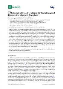
We propose a model capable of determining the positions of multiple nearly equidistant targets using only the overlapping and interfering echoes from each target resulting from a single emission. To determine the location of each of multiple closely positioned targets in 3D space requires cues regarding both the distance and direction to each target. The distances from a bat to objects in a target region, including single or multiple closely positioned targets, are determined by the delay time between the emission and the return of the group of echoes. Also, the spectrogram of echoes from multiple closely positioned targets includes contributions from both the interference between the echoes from different nearly equidistant targets and interference created through the physical process of reception at the external ear. The component of the spectral pattern dependent on the interference between the echoes from the targets is called the ‘‘target dependent spectral pattern (Starget),’’ and the component of the spectral pattern dependent on the interference caused by the physical process of reception at the external ear is called the ‘‘external ear dependent spectral pattern (Sext ear).’’ The Starget and the Sext ear provide information – – for determination of the targets’ distances and directions, respectively, and for this reason, in order to make such determinations, it is necessary to distinguish them within the spectrogram of echoes. The position of each object in the target region is represented by information regarding the distance to the target region as a whole and information regarding the fine-scale structure within this region. The EEDNF associated with the target in question is the frequency corresponding to the minimum amplitude in the Sext ear . In this – model, the necessary mechanism to localize is the method to discriminate between the Starget and the Sext ear from echoes –
J. Acoust. Soc. Am., Vol. 110, No. 1, July 2001
FIG. 1. Diagram of the model. The model consists of four blocks. The inputs to the cochlear block are the emission itself and the echoes reflected from targets.
and then to determine the difference between delay times of echoes from nearly equidistant targets and the EEDNF associated with each target. As shown in Fig. 1, our model consists of four processing blocks. Inputs to the cochlear block are the emission and echoes reflected from objects. This block is followed by two parallel pathways, the temporal and spectral blocks. The function of the temporal block is to determine the distance to the target region, and that of the spectral block is to determine both the difference between delay times of echoes from nearly equidistant targets and the EEDNF associated with each target. Finally, the function of the binaural integration block is to determine a target’s location in 3D space by using cues containing information about the distance to each target and the EEDNF for each target. B. Characteristics of emission and echo
1. Emission
Emissions produced by echolocating bats consist of constant-frequency 共CF兲 and frequency-modulated 共FM兲 Matsuo et al.: Model of echolocation of multiple targets
609
components. There are two types of bat emission patterns, those that consist of CF-FM emissions and those that consist of FM emissions. Bats of the species Myotis lucifugus and Eptesicus fuscus use only FM emissions to locate objects 共Griffin, 1958; Simmons et al., 1995a兲. In our model, we use FM emissions, because the purpose of the model is to identify a target’s location. A single emission of an echolocating bat consists of a principle frequency that sweeps through a range of values 共usually from ⬃10 kHz to ⬃100–200 kHz兲, together with a single or multiple harmonics 共Fenton and Bell, 1981兲. An emission, for example, of Myotis lucifugus has one type of fundamental FM emission. Its duration is from 2 to 5 ms, and its frequency begins at 100 kHz and sweeps through values down to 40 kHz 共Fenton and Bell, 1981兲. In our model, we use an emission having a single FM sweep. The spectrum of the emission has a constant amplitude from 20 to 120 kHz. For this reason, the 3.6-ms-long FM emission begins at 130 kHz and sweeps down to 10 kHz. The rise/fall time is 50 s. The amplitude of the different wavelength components emitted by actual bats depends on the direction of emission 共Hartley and Suthers, 1989; Shimozawa et al., 1974; Simmons et al., 1995b兲. However, because each wavelength is emitted over a large range of directions, in our model we assume no directional dependence of emitted wavelengths for simplicity.
2. Echo
a. Interference of echoes from nearly equidistant targets. We assume the following conditions to simplify the simulation. 共i兲
共ii兲
共iii兲
Each target is a point target. An extended object is considered as consisting of a distribution of acoustically reflecting points, called ‘‘glints’’ 共Altes, 1976兲. In behavioral experiments with simulated targets, situations in which this assumption can be considered valid are created by enabling only one loudspeaker at a time. The reflecting target is a perfect reflector in the sense that it does not modify the phase or amplitude of the sound wave. This assumption simplifies the analysis, because an echo returning from a single reflecting point is an exact copy of the emission. The emitting mouth is midway between two ears, and the distance between the mouth and each ear is 2 cm. This approximates the small head of an echolocating bat.
b. Interference created by physical processes at the external ear. The external ears of the bat Eptesicus fuscus serve as receiving antennas for sonar echoes 共Wotton et al., 1995兲. The transfer function at each external ear varies with the directions 共azimuthal and elevational angles兲 of the targets. The EEDNF ranges from 30 kHz for elevations between 30° and 40° below the horizontal to about 50 kHz for elevations at or near the horizontal 共Wotton et al., 1995兲. Also, for Pallid bats 共Antrozous p. pallidus兲, the EEDNF changes accord610
J. Acoust. Soc. Am., Vol. 110, No. 1, July 2001
ing to some fixed prescription in both azimuthal and elevational directions 共Fuzessery, 1996兲. To simplify our simulation, the EEDNF 共in kHz兲 as a function of the azimuthal and elevational angles 共in degrees兲 of a sound incident to an ear is defined by making reference to the measured transfer function of the external ear of the bats, Eptesicus fuscus 共Wotton et al., 1995兲 as follows: EEDNF共 A,E 兲 ⫽CA/2⫺E/5⫹40,
共1兲
where A and E are the azimuthal and elevational angles of the incident sound. Since the EEDNF is assumed to possess bilateral symmetry, the value of C is 1 for the left ear and ⫺1 for the right ear. Because azimuthal directions from ⫺8° to 8° and elevational directions from 0° to 20° are considered in this simulation, the EEDNF is varied from 31 to 44 kHz. This frequency region is called the ‘‘external ear dependent notch frequency region 共EEDNF region兲.’’ The frequency region outside this region is called the ‘‘non-EEDNF region.’’ A transfer function of the external ear is modeled by a second order infinite impulse response 共IIR兲 filter. The filter’s cutoff bandwidth is 3 kHz, and the attenuation of the amplitude at the notch frequency is 20dB with respect to the maximum. C. Example of emission and echo
The polar coordinate axes (r, , ) are used to represent a target’s location in 3D space. Throughout the paper, we consider the mouth to be at the origin of the coordinate system. Then, r, , and are the distance, azimuthal angle, and elevational angle, respectively, to the target as measured from the position of the mouth. Here, we consider the situation in which three targets are located at 共0.730 m, 0°, 0°兲, 共1.000 m, 0°, 0°兲, and 共1.040 m, 0°, 0°兲, in order to demonstrate the output of the model’s processing due to echoes from a single isolated target and two nearly equidistant targets. The delay times for the respective targets are 4295, 5883, and 6118 s, and the distances from the mouth to each ear via the targets are 1.460, 2.000, and 2.080 m. The difference between delay times for the second and third targets is 235 s, corresponding to 80 mm along the range axis. The EEDNF is 40 kHz for each target, as given by Eq. 共1兲. Figure 2 displays the waveforms of the emission and the returning echoes, which are the inputs to the cochlear block. Since the difference between delay times for the first target and the third target is shorter than the duration of each echo, echoes from the three targets overlap. D. The cochlear block
The function of the cochlear block is to transform the waveforms of the emission and the echoes into the spectrograms in a manner that simulates this process in the mammalian auditory system. The processing of the bat’s inner ear can be modeled by a bandpass filter bank followed by an envelope-smoothing process as proposed by the SCAT model 共Saillant et al., 1993兲. In this model, this bandpass filter bank is composed of the 101 constant-bandwidth, second-order IIR filters. The center frequencies of these filMatsuo et al.: Model of echolocation of multiple targets
FIG. 2. Waveforms and the spectrogram of the emission and the returning echoes. In this case, three targets are located at (r, , ) ⫽(0.730 m,0°,0°), 共1.000 m, 0°, 0°兲, and 共1.040 m, 0°, 0°兲. Here r is a target’s distance from the mouth, is its azimuthal angle, and is its elevational angle. The delay times for the targets are 4295, 5883, and 6118 s, and the distances from the mouth to each ear via the targets are 1.460, 2.000, and 2.080 m. The difference between delay times of the second and third targets is 235 s, corresponding to 80 mm along the range axis. The EEDNF is found to be 40 kHz for each target. Echoes from the three targets overlap with one another. 共b兲 The spectrogram of the emission and the returning echoes exhibits an array of smooth envelopes in the case of a linear frequency modulated 共LFM兲 input signal 共a FM sweep from 130 to 10 kHz in 3.6 ms兲.
ters are spaced from 20 to 120 kHz and are positioned with regular separations. These filter’s bandwidths are the same with ones used by the SCAT model 共Saillant et al., 1993兲. The envelope-smoothing process is modeled by a half-wave rectification and a low-pass filtering of the output of each the 101 bandpass filters 共Brugge et al., 1969; Rose et al., 1967; Russell and Palmer, 1986; Saillant et al., 1993兲. Figure 2共b兲 displays the envelope pattern (Benv), which represents the outputs of the cochlear block for the emission and the echoes. Echoes from the second target and the third target interfere and are not discriminated from each other along the time axis. The use of a 6-dB/oct attenuating low-pass characteristic smoothes the half-wave rectified outputs of the bandpass filters without completely eliminating ripples at these center frequencies 共Saillant et al., 1993兲. E. The temporal block
The function of the temporal block is to determine the delay times corresponding to the onset and offset in a group of echoes. Thus the distance to the nearest target can be directly determined from the delay time corresponding to onset, and the distance to the farthest target can be directly determined from the delay time corresponding to offset. The processing of the temporal block is made up of the three stages. The first stage is the transform from the envelope pattern into the onset and offset patterns at each bandpass J. Acoust. Soc. Am., Vol. 110, No. 1, July 2001
FIG. 3. Determination of the distance to the target region. 共a兲 The extraction of the onset and offset patterns: The envelope pattern in a bandpass filter channel 共center frequency⫽40 kHz兲 共upper left兲, the envelope pattern transformed into the first derivative of the envelope pattern using the sine-wave asymmetric filter 共lower left兲, the onset pattern extracted from the positive part of the first derivative 共upper right兲, and the offset pattern extracted from the negative part of the first derivative are displayed 共lower right兲. 共b兲 Diagram of the integration processing among bandpass filter channels: The onset or offset pattern in each frequency channel is shown in the upper figure. The sweep rate between adjacent filter channels is called ‘‘SR.’’ The values of the onset and offset patterns in a given bandpass filter channel multiply those of the respective patterns in the next lower bandpass filter channel with the time delay SR in Eqs. 共3兲 and 共4兲. The integrated pattern is calculated through the integration processing among the 11 bandpass filter channels. This procedure sharpens the onset and offset peaks, as seen in the lower figure. 共c兲 Final outputs of the temporal block: The solid and dotted curves represent the outputs calculated from the onset and offset patterns, respectively. The delay times corresponding to the peaks of the onset pattern are 4298 and 5858 s, corresponding to 1.461 and 1.992 m along the range axis. The delays times corresponding to the peaks of the offset pattern are 4298 and 6098 s, corresponding to 1.461 and 2.073 m, respectively. The distance to the first group of echoes is 1.461 m, and the distance to the second group of echoes ranges from 1.992 to 2.073 m along the range axis.
filter channel. The second stage is the integration processing among bandpass filter channels to improve the temporal precision. The third stage is the cross-correlation function between the emission and the echoes returning from targets. Matsuo et al.: Model of echolocation of multiple targets
611
The onset and offset patterns are obtained from the envelope pattern, which is the output from the cochlear block 关Fig. 3共a兲兴. The envelope pattern of the emission (Benv) in one bandpass filter channel 共with center frequency 40 kHz兲 includes ripples due to the characteristic of the low-pass filter at the cochlear block. To determine the onset and offset delay times not in these ripples but in the group of echoes from a single or nearly equidistant targets along the range axis requires extracting the change in envelope’s magnitude without these ripples along the time axis. Therefore, it needs both the low-pass filter attenuating enough at 20 kHz of the emission’s minimum frequency and the filter to extract the change in envelope’s magnitude along the time axis. For this reason, the envelope pattern is transformed into the first derivative pattern by deconvolution of a sine-waveform asymmetric filter with a period of 350 s. This asymmetric filter is represented by W asym共 t 兲 ⫽sin 共 2 t/T 兲 ,
0⬍t⬍T,
共2兲
where t is time and T is the period 共⫽350 s兲. The onset pattern (Bon) and the offset pattern (Boff) are the positive part and the negative part of the derivative pattern, respectively. This process has no effect on the determination of the delay time because of deconvoluting both the emission’s and echo’s envelope patterns in the same way. In the integration processing among bandpass filter channels, the precision of the temporal block is improved by integrating the onset and offset patterns of different bandpass filter channels. As shown in Fig. 3共b兲, the sweep rate between adjacent bandpass filter channels is referred to as ‘‘SR’’共⫽30 s/kHz兲. The values of onset or offset pattern in a bandpass filter channel multiply those of the respective pattern in the next lower bandpass filter channel with a time delay SR. A bank of integrated filters is composed of 19 integrated filter channels whose center frequencies range from 25 to 115 kHz at regular separation 共channel number: 0 at 115 kHz to 18 at 25 kHz兲. In our model, an 18-kHz integrated filter channel bandwidth is obtained by integrating over 11 bandpass filter channels. The Q 10dB values range from 1.4 at 115 kHz to 6.3 at 25 kHz. This integrated filter 共IF兲 in the nth frequency channel is described by the equations: 5
IFon共 f n ,t 兲 ⫽
兿 Bon共 f n ⫹FD⫻i,t⫺SR⫻i 兲 , i⫽⫺5
共3兲
5
IFoff共 f n ,t 兲 ⫽
兿
i⫽⫺5
Boff共 f n ⫹FD⫻i,t⫺SR⫻i 兲 ,
共4兲
where f n 共kHz兲 is the center frequency for the nth integrated filter channel and t is time 共in seconds兲. The quantity FD 共⫽1kHz兲 is the frequency difference between bandpass filter channels. The transform of the time axis into the range axis is carried out by the coincidence circuit, which calculates the cross-correlation function between the emission and the echoes. This cross-correlation function for the nth integrated filter channel is represented by the following equations: 612
J. Acoust. Soc. Am., Vol. 110, No. 1, July 2001
Con共 f n , i 兲 ⫽ Coff共 f n , i 兲 ⫽
i ⫽ 0 ⫹id ,
冕 冕
IFon共 f n ,t⫹ i 兲 IFon共 f n ,t 兲 dt,
共5兲
IFoff共 f n ,t⫹ i 兲 IFoff共 f n ,t 兲 dt,
共6兲
i⫽0,1,2,3,...,70,
共7兲
where the value i is the delay time corresponding to the ith coincidence-detecting cell, and the quantity d is the difference between delay times corresponding to consecutive coincidence-detecting cells. In this model, we set d ⫽60 s 共which corresponds to a distance 20.4 mm along the range axis兲, because the interval between BDs of delay-tuned neurons in the CF/FM bat Pteronotus parnellii is about 100 s 共Suga and O’Neill, 1979兲. The final outputs of the temporal block 共Oon and Ooff兲 are calculated by summing up the outputs of 19 integrated filter channels at each delay time: Oon共 i 兲 ⫽
兺f Con共 f n , i 兲 ,
共8兲
兺f Coff共 f n , i 兲 .
共9兲
n
Ooff共 i 兲 ⫽
n
The differences between the onset and offset delay times corresponding to the distances to the nearest and farthest targets, for a group of the echoes returning from single or multiple nearly equidistant targets, are determined from Oon and Ooff . F. Examples of outputs from the temporal block
The solid curve in Fig. 3共c兲 represents the output resulting from the onset pattern along the range axis. The peak delays are 4298 and 5858 s, corresponding to 1.461 and 1.992 m along the range axis. The dotted curve in Fig. 3共c兲 represents the output resulting from the offset pattern along the range axis. The peak delays are 4298 and 6098 s, corresponding to 1.461 and 2.073 m. Thus, the first group of echoes corresponds to 1.461 m and the second group from 1.992 to 2.073 m along the range axis. We thus see that important information about the target distances can be obtained from the onset and offset patterns. G. The spectral block
The function of the spectral block is to determine the differences among delay times of echoes from nearly equidistant targets and the EEDNF associated with each target. For this reason, it needs to distinguish between the Starget and the Sext ear in the spectrogram resulting from echoes return– ing from nearly equidistant targets. From the measurement of the external ear’s transfer functions of real bats, it has been found that the EEDNF varies within the somewhat restricted frequency range 共Wotton et al., 1995兲. While in the EEDNF region the spectrogram includes contributions from both the Starget and the Sext ear, in the non-EEDNF region, the spec– trogram contains only the Starget . For this reason, when the deconvolution of the basis vectors 共see the Appendix兲 is applied to the echo spectral pattern (Secho) in the non-EEDNF Matsuo et al.: Model of echolocation of multiple targets
FIG. 4. Diagram describing the extraction of the peak pattern. 共a兲 The second derivative calculated by extracting the change in the magnitude of the first derivative 关see Fig. 3共b兲兴 along the time axis. 共b兲 The peak pattern is the negative part of the second derivative.
region, this is transformed into an impulse response resulting only from the interference between echoes from targets. The difference between delay times can be determined from the peak time in this impulse response along the time axis. To extract the Sext ear we need to determine the Starget in the – in the EEDNF region. However, the Starget EEDNF region cannot be reconstructed from this impulse response which is calculated from the Secho in the nonEEDNF region. Since the Starget is dependent on the difference between delay times, the Starget in the EEDNF region can be extrapolated from information on the difference between delay times calculated from the Secho within the nonEEDNF region and then the Sext ear can be determined by – subtracting the Starget from the Secho . The spectrograms of the emission and the echoes returning from targets are transformed into the range-frequency representation by using the cross-correlation function between the emission and the echoes in each bandpass filter channel. In order to discriminate echoes from nearly equidistant targets, the spectrum of the echo associated with each target must be extracted more precisely. Therefore, it needs to improve the temporal precision of the emission’s pattern. For this reason, the second derivative of the spectrogram is calculated by extracting the change in the magnitude of the first derivative of the envelope pattern 关see Fig. 3共a兲兴. As shown in Fig. 4共b兲, the peak pattern is the negative part of the second derivative of the spectrogram. Since the width of the peak pattern is shorter than the width of the envelope pattern, the range-frequency pattern is obtained from the cross-correlation function between the emission’s peak pattern (Bpeak) and the echo’s envelope pattern (Benv) at the nth bandpass frequency channel as follows: C共 f n , i 兲 ⫽
冕
i ⫽ 0 ⫹id ,
Bpeak共 f n ,t⫹ i 兲 Benv共 f n ,t 兲 dt, i⫽0,1,2,3,...,70.
共10兲
Here C( f n , i ) is the cross-correlation function between an emission and its resulting echoes. The quantity i is the delay time, and d is the time interval between delay times to coincidence-detecting cells. These values correspond to the values for the cross-correlation function in the temporal block. The difference between delay times of echoes from nearly equidistant targets is calculated from the Secho associated with the average ( ave) of delay times corresponding to the onset and offset for a group of echoes, since the Secho associated with the average delay time is strongly influenced J. Acoust. Soc. Am., Vol. 110, No. 1, July 2001
FIG. 5. Diagram of the spectral block. 共a兲 The Secho includes contributions from the interference between echoes from nearly equidistant targets and the interference created by the physical process of reception at the external ear. 共b兲 The Secho associated with the point half-way between the onset and offset delay times in non-EEDNF region includes a contribution only from the interference between echoes from nearly equidistant targets. 共c兲 The Secho associated with the point half-way between the onset and offset delay times in the non-EEDNF region is transformed into the Isel pass through the decon– volution of the selective-pass basis vectors. 共d兲 The reduced impulse response is represented by extracting the values of the Isel pass at t⫽0 and t – ⫽peak time equal to the difference between delay times. 共e兲 The reduced impulse response is transformed into the Starget through the convolution of the all-pass basis vectors. 共f兲 The Secho associated with the delay time corresponding to each target is transformed into the associated Iecho through the deconvolution of the all-pass basis vectors. 共g兲 The Starget is transformed into the Itarget through the deconvolution of the all-pass basis vectors. 共h兲 The subtracted impulse response is calculated by subtracting the Itarget from the Iecho. 共i兲 The subtracted impulse response is transformed into the Sext ear – through the convolution of the all-pass basis vectors. The EEDNF corresponding to each target is the frequency corresponding to the minimum of the amplitude in the Sext ear. –
by the interference of the echoes returning from nearly equidistant targets. The Secho associated with the average delay time is obtained as the logarithm of the cross-correlation function log„C( f n , ave)… using the interpolation. Since the Secho of the average delay time in the non-EEDNF region only includes a contribution from the interference between echoes from nearly equidistant targets, the Secho of the average delay time in this region 关Fig. 5共b兲兴 can be transformed into the impulse response 关Fig. 5共c兲兴 using the deconvolution of the selective-pass improved basis vectors 共see the Appendix兲. This impulse response is called the ‘‘selective-pass impulse response (Isel pass).’’ The difference between delay – times of echoes is determined from the peak time of the Isel pass. – To determine the Sext ear in the EEDNF region requires – extrapolating the Starget in the EEDNF region from the Secho in the non-EEDNF region. For this reason, we extract the values of the Isel pass at t⫽0 and t⫽peak time equal to the – difference between delay times. The extracted impulse response 关Fig. 5共d兲兴 is called the ‘‘reduced impulse response.’’ Matsuo et al.: Model of echolocation of multiple targets
613
The reduced impulse response is transformed into the Starget 关Fig. 5共e兲兴 in the entire frequency region using the convolution of the all-pass basis vectors 共see the Appendix兲. If the shape of the Starget is similar to that of the Secho at the average delay time in the non-EEDNF region, the difference between delay times of echoes from nearly equidistant targets can be considered to be the peak time. The EEDNF corresponding to each target can be determined by comparing the Starget and the Secho associated with the delay time for the target in question. The delay time for the nearest target is equal to that of the onset of the group of echoes. The delay time for the farthest target is determined by adding the delay time for the nearest target and the difference between delay times of the echoes from the nearly equidistant targets. The Secho associated with the delay time 共兲 for each target is calculated as log „C( f n , )…. The amplitudes of peak and notch frequencies for the Starget are shifted to coincide with those of peak and notch frequencies at the Secho associated with the target 关Figs. 5共a兲 and 共e兲兴. The Secho associated with each target and the Starget 关Figs. 5共a兲 and 共e兲兴 are transformed into the echo and target dependent impulse responses 共Iecho and Itarget兲, respectively 关Figs. 5共f兲 and 共g兲兴, through the deconvolution of the all-pass improved basis vectors. In order to eliminate the component relating to the difference in delays (ªt peak), it needs to correct the Itarget. For this reason, Itarget is corrected in accordance with the stipulation that Itarget(t peak) coincide with Iecho(t peak) in Eq. 共11兲 and this corrected impulse response is called ‘‘the corrected target dependent impulse response (Icor tar):’’ –
Iecho共 t peak兲 Icor tar共 t 兲 ⫽ I 共 t 兲. – Itarget共 t peak兲 target
共11兲
As shown in Fig. 5共h兲, the external ear dependent impulse response (Iext ear) can be determined by subtracting the – Icor tar from the Iecho as follows: –
Iext
共 t 兲 ⫽Iecho共 t 兲 ⫺Icor – tar共 t 兲 .
– ear
共12兲
The Iext ear is transformed into the Sext ear 关Fig. 5共i兲兴 – – through the convolution of the all-pass improved basis vectors 共see the Appendix兲. The EEDNF associated with each target is the frequency corresponding to the minimum amplitude of the Sext ear. In this way, the difference between delay – times for each target and the EEDNF associated with each target are obtained as outputs of the spectral block. H. Examples of outputs from the spectral block
Figure 6 exhibits outputs of the selective-pass impulse response associated with the first and second group of echoes along the range axis 关see Fig. 3共c兲兴. Figure 6共a兲 displays the Secho of the average delay time for the first group of echoes, whose distance is 1.461 m. The spectral pattern in the nonEEDNF region has almost a constant amplitude in the nonEEDNF region, and the Isel pass is almost constant, except for – the existence of a peak at t⫽0 along the time axis, as shown in Fig. 6共b兲. It was found that the first group of echoes results from a single target. The Sext ear is identical to the Secho here, – because in this case the spectral pattern includes only the 614
J. Acoust. Soc. Am., Vol. 110, No. 1, July 2001
FIG. 6. Determination of the difference between delay times. 共a兲 The Secho associated with the point half-way between the onset and offset delay times in the first group of echoes. The point half-way between the onset and offset delay times corresponds to 1.461 m along the range axis. This Secho has a constant amplitude in the non-EEDNF region. 共b兲 Isel pass. The Isel pass is – – normalized by the value corresponding to t⫽0 along the time axis. The Isel pass is almost constant along the time axis, except for the peak at t⫽0. It – is thus concluded that the first target region contains a single target. 共c兲 The Secho associated with the point half-way between the onset and offset delay times 共corresponding to 2.033 m兲 in the second group of echoes. 共d兲 Isel pass. – The difference between delay times is 235 s, corresponding to 80 mm along the range axis.
interference created by the physical process of the reception at the external ear. The calculated EEDNF to the target at each ear is 40 kHz. Figures 6共c兲 and 共d兲 display the Secho of the average delay time for the second group of echoes and the Isel pass. The difference between delay times is 235 s, – corresponding to 80 mm along the range axis, as obtained from the peak time of the Isel pass. – The solid curve in Fig. 7共a兲 represents the Secho associated with the nearest target and the dotted curve represents the Starget. The Secho associated with the nearest target differs slightly from the Starget because the peak and notch frequencies change along the range axis. Figure 7共b兲 displays the Iecho and Icor tar, and Fig. 7共c兲 displays the subtracted impulse – response. The solid curve in Fig. 7共d兲 represents the Sext ear, – and the calculated EEDNF is 40 kHz. The dotted curve in this figure represents the spectral pattern (Ssub) which is obtained by subtracting the Starget 关Fig. 7共a兲 dotted line兴 from Matsuo et al.: Model of echolocation of multiple targets
FIG. 8. Determination of the EEDNF associated with the farthest target corresponding to the second group of echoes. 共a兲 The Secho associated with the delay time of the farthest target 共solid curve兲 and the Starget 共dotted curve兲. 共b兲 The Iecho 共solid curve兲 and the Itarget 共dotted curve兲. 共c兲 Sext ear – calculated from the subtracted impulse response. The calculated EEDNF is 40 kHz.
to the difference between delay times, 235 s. The calculated EEDNF is 40 kHz, as shown in Fig. 8共c兲. FIG. 7. Determination of the EEDNF associated with the nearest target corresponding to the second group of echoes. 共a兲 The Secho associated with the delay time of the nearest target 共solid curve兲 and the Starget 共dotted curve兲. 共b兲 The Iecho 共solid curve兲 and the Itarget 共dotted curve兲. 共c兲 Subtracted impulse response. 共d兲 Sext ear are obtained from the subtracted impulse re– sponse calculated in Eq. 共12兲 共solid curve兲, and the spectral pattern that is obtained by subtracting the Starget from the Secho associated with the nearest target along the frequency axis in Eq. 共13兲 共dotted curve兲. The value of the EEDNF calculated by subtracting these impulse responses along the time axis is 40 kHz. In contrast, the value of the EEDNF calculated by subtracting along the frequency axis is 39 kHz.
the Secho associated with the nearest target 关Fig. 7共a兲 solid line兴 as follows: Ssub共 f 兲 ⫽Secho共 f 兲 ⫺Starget共 f 兲 .
共13兲
In this case, the calculated EEDNF is 39 kHz. The difference between the two values of the EEDNF indicates that its value for each target can be more accurately obtained by using the impulse responses along the time axis rather than using the Secho and the Starget along the frequency axis. The solid curve in Fig. 8共a兲 represents the Secho associated with the farthest target, and the dotted curve represents the Starget. The Starget is similar to the Secho associated with the farthest target in the non-EEDNF region. As shown in Fig. 8共b兲, the Iecho corresponds to the Icor tar around the time equal –
J. Acoust. Soc. Am., Vol. 110, No. 1, July 2001
I. The integration block
In the binaural integration block, each target in 3D space is located using two pieces of information regarding the distance to the target and the EEDNF associated with the target. The distance to the nearest target in the target region can be obtained directly from the delay time corresponding to the onset, which is given as an output of the temporal block. The distance to the farthest target is determined by adding the distance to the nearest target and the distance corresponding to the difference between delay times of the echoes from the two nearly equidistant targets. Each curve in Fig. 9共a兲, drawn in a horizontal plane, represents equal distances. Each curve corresponds to the distance 共calculated in the manner described above兲 from the mouth to one of the ears, via one of the targets. Four possible locations are determined for each target’s position in a horizontal plane by using the interaural range difference 共IRD兲, which is equivalent to the ITD. However, it is difficult to precisely determine the target’s azimuthal direction by using only the information on the IRD between nearest targets (IRDnear) because of the smallness of the bat’s head. By using the directional information concerning the EEDNF associated with each target, our model can uniquely determine the location of each target in 3D space from the possible positions determined in the manner previMatsuo et al.: Model of echolocation of multiple targets
615
TABLE I. The distances and EEDNFs corresponding to five actual targets. Target’s location 共r,a ,b b兲 共0.734, 共0.850, 共1.064, 共1.201, 共1.351,
6, 0兲 0, 0兲 0, 20兲 ⫺8, 15兲 2, 0兲
Distancea 共Delay timec兲 Left ear 1.470 1.700 2.129 2.400 2.702
共4325兲 共5001兲 共6260兲 共7060兲 共7949兲
Right ear 1.466 1.700 2.129 2.400 2.701
共4312兲 共5001兲 共6260兲 共7076兲 共7944兲
EEDNFd Left ear
Right ear
43 40 36 33 41
37 40 36 41 39
a
The distance unit is meters. The unit is degrees. c The unit is microsecond. d The unit is kHz. b
the EEDNFs 共⫽40 kHz兲 associated with the two ears 关see Fig. 9共b兲兴. Also, the results indicate that the second group of echoes has two targets. From the difference between delay times 共⫽235 s兲 for the two ears, the azimuthal direction associated with the nearest target is found to be the same as the azimuthal direction of the farthest target. By using the EEDNF 共⫽40 kHz兲 corresponding to each target, two target’s direction in the second group of echoes is determined to be ( , )⫽(0.0°,0.0°). From these results, we conclude that our model can accurately locate the three targets. III. RESULTS A. Multiple targets without interference among echoes from different targets
FIG. 9. Determination of the target direction. 共a兲 The curves represent equal from mouth-to-ear distances via two targets in a horizontal plane. The black curves correspond to the left ear and the gray curves correspond to the right ear. Four possible locations are determined for each target’s position in a horizontal plane by using the interaural range difference 共IRD兲. The IRD between nearest targets (IRDnear) varies from ⫺16 to 16 s 共corresponding to azimuthal angles from ⫺8° to 8°兲 as results from the head size. In accordance with the IRDnear, the IRDfar determines possible locations for the farthest target in a horizontal plane. 共b兲 EEDNF as a function of sound direction. The solid and dashed lines represent the EEDNF for the left and right ears, respectively. The EEDNF changes according to some fixed prescription in both azimuthal and elevational directions. 共c兲 Final output of the integration block. The direction of each target 共block square兲 is determined as ( , )⫽(0°,0°).
ously described. The direction to a target is the direction whose notch frequency in the template set is the same as the calculated EEDNF. Thus, the target direction can be calculated by requiring that the difference between the notch frequency in the template set and the calculated EEDNF be the minimum. Figure 9共c兲 displays outputs of the integration block. From this, we see that the direction to the target in the first group of echoes is ( , )⫽(0.0°,0.0°) as determined from 616
J. Acoust. Soc. Am., Vol. 110, No. 1, July 2001
As an example of the case of an arbitrary number of targets in 3D space, we consider that in which there exist five targets and the echoes returning from them overlap but do not interfere with each other. The locations of the five targets are (r, , )⫽(0.734 m,6°,0°), 共0.850 m, 0°, 0°兲, 共1.064 m, 0°, 20°兲, 共1.201 m, ⫺8°, 15°兲, and 共1.351 m, 2°, 0°兲. The distances from the mouth to two ears via the five targets and the EEDNF corresponding to each target at each ear are listed in Table I. The waveforms and spectrograms of the emission and the echoes returning from the five targets are displayed in Figs. 10共a兲 and 共b兲. We see from these figures that the echoes from the targets overlap but do not interfere with each other. Figures 10共c兲 and 共d兲 display the outputs of the temporal block. The five clear peaks of each curve indicate the delay times for the five targets. These peaks allows us to determine the distances from the mouth to two ears via each target, as listed in Table II. Comparing Table II to Table I, it is clear that the model of the temporal block can closely determine the distances to the targets. In the present case, the echoes from the five targets overlap but do not interfere with each other, so the differences between delay times corresponding to the different targets is on the order of several hundred to several thousand microseconds. Therefore, the echo returning from each target can be easily separated, and the two EEDNFs for each of the five targets can be calculated from the Secho associated with each target. Each Secho is almost constant in the non-EEDNF region, and the Isel pass corresponding to the first target for the – left ear has no peaks along the time axis, except for a peak at t⫽0, as shown in Fig. 10共f兲. This means that only one target Matsuo et al.: Model of echolocation of multiple targets
FIG. 10. Multiple targets with no interference among echoes from targets. Five targets are located at (r, , )⫽(0.734 m,6°,0°), 共0.850 m, 0°, 0°兲, 共1.064 m, 0°, 20°兲, 共1.201 m, ⫺8°, 15°兲, and 共1.351 m, 2°, 0°兲. 共a兲 Waveforms of the emission and the returning echoes. 共b兲 Spectrogram of the emission and the echoes. The echoes from the five targets overlap but do not interfere with each other. 共c兲 and 共d兲 Outputs of the temporal block for left and right ears, respectively. The solid and dotted curves represent outputs obtained from the onset and offset patterns, respectively. The five clear peaks of each curve indicate the delay times to the five targets. As shown in Table II, the distances from the mouth to the two ears for the targets can be determined from this information. 共e兲 The Secho associated with the point half-way between the onset and offset delay times in the first group of echoes 共corresponding to a distance of 1.461 m兲. 共f兲 Isel pass for the first group of echoes. Since the Isel pass has no peaks except a peak at t⫽0 along the time axis, it indicates that the first target region contains – – only a single target. For this reason, the Secho associated with the delay time of the target is identical to the Sext ear, and the EEDNF is 43 kHz. 共g兲 The – directions of the five targets. The calculated direction 共, 兲 is 共6.0°, 0.0°兲 for the first target 共solid square兲, 共0.0°, 0.0°兲 for the second target 共open square兲, 共0.0°, 20.0°兲 for the third target 共open triangle兲, 共⫺8.0°, 15.0°兲 for the fourth target 共solid triangle兲, and 共2.0°, 0.0°兲 for the fifth target 共open circle兲. Each of these calculated directions is in good agreement with the actual direction.
is contained in the first target region. The EEDNFs obtained for the first target are 43 kHz for the left ear and 37 kHz for the right ear. The EEDNFs were obtained similarly for the other four targets. The results are listed in Table II. Finally, the direction to each target is determined by using these EEDNFs, as shown in Fig. 10共g兲. These directions 共, 兲 are 共6.0°, 0.0°兲, 共0.0°, 0.0°兲, 共0.0°, 20.0°兲, 共⫺8.0°, 15.0°兲, and 共2.0°, 0.0°兲. These results are in good agreement with the actual target directions.
B. Two targets with the almost same distance but different direction
We now consider the case in which two targets are located at the almost same distance but different directions. The two targets are located at (r, , )⫽(0.734 m,6°,0°) and 共0.768 m, ⫺4°, 20°兲. The distances from the mouth to the ear via the first target are 1.470 m 共⫽4325 s兲 and 1.466 m 共⫽4312 s兲 for the left and right ears, respectively, and the
TABLE II. Outputs of the temporal and spectral blocks for five targets. Calculated results from the temporal block Onset Distance 共Delay timec兲
Offset Distance 共Delay timec兲
b
No.a 1 2 3 4 5
Left ear 1.461 1.706 2.135 2.400 2.706
共4298兲 共5018兲 共6278兲 共7058兲 共7958兲
b
Right ear 1.461 1.706 2.135 2.400 2.706
共4298兲 共5018兲 共6278兲 共7058兲 共7958兲
Left ear 1.461 1.706 2.135 2.400 2.706
共4298兲 共5018兲 共6278兲 共7058兲 共7958兲
Right ear 1.461 1.706 2.135 2.400 2.706
共4298兲 共5018兲 共6278兲 共7058兲 共7958兲
Calculated EEDNFd of the spectral block Left ear
Right ear
43 40 36 33 41
37 40 36 41 39
a
The numbers are in order of the onset distance. The distance unit is meters. c The unit is microseconds. d The unit is kHz. b
J. Acoust. Soc. Am., Vol. 110, No. 1, July 2001
Matsuo et al.: Model of echolocation of multiple targets
617
FIG. 11. Outputs in the case of two targets at almost equal distances but different directions. The two targets are located at (r, , )⫽(0.734 m,6°,0°) and 共0.768 m, ⫺4°, 20°兲. The delay times associated with the first target are 4325 s 共⫽1.470 m兲 for the left ear and 4312 s 共⫽1.466 m兲 for the right ear. The delay time associated with the second target are 4514 s 共ª1.535 m兲 for the left ear and 4521 s 共ª1.537 m兲 for the right ear. 共a兲 The waveforms of the emission and the returning echoes. 共b兲 Spectrogram of the emission and the echoes. 共c兲 and 共d兲 Outputs of the temporal block for the left ear and the right ear, respectively. The solid curve represents the output calculated from the onset pattern and the dotted curve represents the output calculated from the offset pattern. 共c兲 The delay times corresponding to the peaks of the onset and offset patterns are 4358 s 共⫽1.482 m兲 and 4478 s 共⫽1.522 m兲. 共d兲 The delay times corresponding to the peaks of the onset and offset patterns are 4298 s 共⫽1.461 m兲 and 4538 s 共⫽1.543 m兲. 共e兲 The Secho associated with the point half-way between the onset and offset delay times for the left ear. The point half-way between the onset and offset delay times corresponds to 1.502 m along the range axis. 共f兲 Isel pass. The difference between delay times of echoes from nearly equidistant target is 189 s. 共g兲 and 共h兲 Determination of the EEDNF for the left – and right ears, respectively. The solid and dotted lines display the Sext ear associated with the nearest and farthest targets. 共g兲 The EEDNFs are 43 kHz for the – nearest target and 36 kHz for the farthest target. 共h兲 The EEDNFs are 37 kHz for the nearest target and 38 kHz for the farthest target. 共i兲 Calculated directions of the two targets. The direction of the nearest target 共solid square兲 is 共6.8°, 1.0°兲, and that of the farthest target 共gray square兲 is 共⫺3.2°, 15.0°兲.
distances from the mouth to the ear via the second target are 1.535 m 共⫽4514 s兲 and 1.537 m 共⫽4521 s兲 for the left and right ears, respectively. The differences between delay times of the two targets are 189 s 共corresponding to 64.3 mm兲 for the left ear and 209 s 共corresponding to 71.1 mm兲 for the right ear. The EEDNFs corresponding to the nearest target are 43 kHz for the left ear and 37 kHz for the right ear. The EEDNFs corresponding to the farthest target are 34 kHz for the left ear and 38 kHz for the right ear. Figures 11共a兲 and 共b兲 display the waveforms of the emission and the echoes returning from the two targets and the output of the cochlear block, respectively. Figure 11共c兲 displays the output of the temporal block for the left ear. The delay times at the peaks for the onset and the offset are 4358 s 共⫽1.482 m兲 and 4478 s 共⫽1.522 m兲, respectively. As shown in Fig. 11共d兲, for the right ear, the delay times at the 618
J. Acoust. Soc. Am., Vol. 110, No. 1, July 2001
onset and offset are 4298 s 共⫽1.461 m兲 and 4538 s 共⫽1.543 m兲, respectively. Figure 11共f兲 displays the Isel pass. – This figure indicates that the average of the distances from the two targets to the left ear is 1.502 m and the difference between delay times for the two echoes returning from the targets is 189 s 共corresponding to 64.2 mm兲 for the left ear. In the same way, the average distance and the difference in delay times for the right ear are obtained as 1.502 m and 209 s 共corresponding to 71.0 mm兲. The solid and dotted curves in Fig. 11共g兲 for the left ear and Fig. 11共h兲 for the right ear represent the Sext ear for the nearest and farthest target, re– spectively. From the left Sext ear, the EEDNFs are obtained – as 43 kHz for the nearest target and 36 kHz for the farthest one, the latter of which differs slightly from the actual value of 34 kHz. Similarly, at the right ear, the EEDNFs are found Matsuo et al.: Model of echolocation of multiple targets
to be 37 kHz for the nearest target and 38 kHz for the farthest target, which are consistent with their actual values. Integrating these results, we obtain the direction to the nearest target as 共6.8°, 1.0°兲 and to the farthest target as 共⫺3.2°, 15.0°兲. There are slight discrepancies between these values and the actual values. However, this discrepancies are acceptable, because the bats appear to determine the direction of an echo’s source to within ⫾2°⫺⫾5° 共Grinnell, 1995; Masters et al., 1985; Simmons et al., 1995a兲. C. Resolution of two very closely located targets
It has been reported that the FM bat Eptesicus fuscus can accurately distinguish between two targets with a difference between delay times as small as 2.6 s 共Saillant et al., 1993; Simmons et al., 1995a兲. However, they also found that if the cross-correlation function method is used, two glints whose difference between delay times is 10 s or smaller cannot be discriminated 共Saillant et al., 1993兲. To study this situation, we consider the case in which two targets are located at (r, , )⫽(0.7300 m,0°,0°) and 共0.7308 m, 0°, 0°兲. The distances from the mouth to the ear via the nearest and the farthest target are 1.460 m 共⫽4294.1 s兲 and 1.4616 m 共⫽4298.8 s兲, Thus, there is the difference between delay times of 4.7 s 共⫽1.6 mm兲. Each of the four EEDNFs corresponding to these targets is 40 kHz. Figures 12共a兲 and 共b兲 display the waveforms and the spectrograms of the emission and the echoes from the two targets. Figure 12共c兲 exhibits the cross-correlation function for the emission and the echoes from the two targets. As seen, it contains only one peak, at the point half-way between the delay times of the echoes from the two targets. This suggests that it is difficult to determine the difference in delays between delay times for echoes from nearly equidistant targets using only the cross-correlation function. The outputs of the temporal block are shown in Fig. 12共d兲. This indicates that the two targets are located in the vicinity of 4298 s 共⫽1.461 m兲 along the range axis. Figure 12共e兲 displays the Isel pass. The calculated differ– ence between delay times for the two targets is 4.1 s 共⫽1.4 mm兲. Although this value differs slightly from the true value, our model has successfully determined that there are two nearly equidistant targets. Each of the four EEDNFs is found to be 40 kHz, as shown in Fig. 12共f兲. This implies that the directions of both targets are 共0.0°, 0.0°兲 in agreement with the actual values. D. Robustness in a noisy environment
Echolocating bats can reliably discriminate multiple targets in a noisy environment 共Griffin, 1958兲. The FM bat Eptesicus fuscus can determine the arrival time of an echo with a precision of within 40 ns at an echo energy signal-tonoise ratio of 36 dB 共Simmons et al., 1990a兲. To investigate the robustness of our model, we added a broadband white random noise to the echoes, following Saillant et al. 共1993兲. The noise is characterized by the ratio of the root mean square 共rms兲 amplitude of the echo of a single point and the rms amplitude of the white noise during a control interval preceding the emission. J. Acoust. Soc. Am., Vol. 110, No. 1, July 2001
FIG. 12. Resolution of two closely located targets. Two targets are located at (r, , )⫽(0.7300 m,0°,0°) and 共0.7308 m, 0°, 0°兲. The delay times are 4294.1 s 共⫽1.4600 m兲 for the first target and 4298.8 s 共⫽1.4616 m兲 for the second target. The difference between delay times of echoes from the two targets is 4.7 s 共⫽1.6 mm兲. 共a兲 The waveforms of the emission and the echoes. 共b兲 Spectrogram of the emission and the echoes. 共c兲 The crosscorrelation function between the emission and the echoes. This function has a single peak located at the point half-way between the onset and offset delay times of echoes from the two targets. In this case, it is impossible to determine the difference between delay times of the echoes from very closely positioned targets using only the cross-correlation function. 共d兲 Output of the temporal block. The delay times corresponding to the peaks of the onset and offset patterns are both 4298 s 共⫽1.461 m兲. 共e兲 Isel pass. The – difference between delay times is 4.1 s. The arrow shows the 4.1-s location. 共f兲 Sext ear associated with the nearest target for the left ear. The – EEDNF is 40 kHz. Matsuo et al.: Model of echolocation of multiple targets
619
and the offset of the group of echoes are found to be 4298 s 共⫽1.461 m兲 and 4298 s 共⫽1.461 m兲 for both ears, as shown in Fig. 13共c兲. Figure 13共d兲 displays the Isel pass. The calcu– lated difference between delay times is 46.8 s 共⫽15.9 mm兲, which is in good agreement with the actual difference between delay times. Figure 13共e兲 displays the Sext ear associ– ated with the nearest target for the left ear. The EEDNF calculated is 40 kHz. The EEDNF associated with each target for each ear was similarly calculated and found to be 40 kHz, in good agreement with the actual values. These results indicate that the direction to each target is 共0.0°, 0.0°兲. We thus find that in spite of the existence of noise, the locations of the targets can be accurately determined.
IV. DISCUSSION AND CONCLUSION
FIG. 13. Robustness in a noisy environment. The signal-to-noise ratio is 5 dB. Two targets are located at (r, , )⫽(0.730 m,0°,0°) and 共0.738 m, 0°, 0°兲. The delay times are 4295 s 共⫽1.460 m兲 for the first target and 4342 s 共⫽1.476 m兲 for the second target. The difference between delay times of echoes from the targets is 47 s. The EEDNF is 40 kHz for both ears and both targets. 共a兲 The waveforms of the emission and the echoes. 共b兲 Spectrogram of the emission and the echoes. 共c兲 Outputs of the temporal block. The solid curve represents the output calculated from the onset pattern and the dotted curve represents the output calculated from the offset pattern. The delay times corresponding to the peaks of the onset and offset patterns are both 4298 s 共⫽1.461 m兲. 共d兲 Isel pass. The difference between delay times – of echoes from the two targets is 46.8 s 共⫽15.9 mm兲. 共e兲 Sext ear associated – with the nearest target. The EEDNF for the nearest target is 40 kHz.
In this study, two targets are located at (r, , ) ⫽(0.730 m,0°,0°) and 共0.738 m, 0°, 0°兲. The rms amplitude signal-to-noise ratio for a single target is 5.0 dB. The distances from the mouth to the ear via the nearest and farthest targets are 1.460 m 共⫽4295 s兲 and 1.476 m 共⫽4342 s兲. The difference between delay times for the two targets is 47 s 共⫽16 mm兲. All EEDNFs for the two targets and two ears are 40 kHz. Figures 13共a兲 and 共b兲 display the waveforms and spectrograms of the emission and the returning echoes. From the outputs of the temporal block, the delay time for the onset 620
J. Acoust. Soc. Am., Vol. 110, No. 1, July 2001
Echolocating bats emit trains of high-frequency sounds and recognize individual targets in the real world. Since bats are able to capture a moving target in the presence of multiple objects, it appears that they may be able to determine the locations of multiple targets using the echoes produced by a single emission. In order to locate objects in 3D space, bats need to process the returning echoes to determine the distance and direction to each object. The model to determine the distance and direction of moving, multiple targets by using both the Doppler shift and amplitude change of CF echoes was proposed 共Mu¨ller and Schnitzler, 2000兲. However, it is difficult to discriminate echoes from closely spaced targets and to localize these targets because of the interference between echoes. In the field of the radar and sonar, for example, Liu and Xiang 共1999兲 proposed the computational algorithm to determine the distances of unknown, multiple targets. However, this cannot determine the location of targets in 3D space because of using the information on only the distance to targets. Also, Swindlehurst and Gunther 共1999兲 proposed the computational algorithm to localize multiple targets in 3D space by using the receiving array. However, in the case of restricting two receivers, it is hard to localize multiple targets in 3D space. In this model, we have introduced four blocks applying different processes to analyze the information obtained from echoes to locate multiple targets in 3D space. The waveforms of the emission and the returning echoes are processed in the cochlear block, where they are transformed into a spectrogram. In the temporal block, the distance to the nearest and farthest targets of a set of targets is determined from the delay times from the emission to the onset and offset of the group of returning echoes. In the spectral block, the range-frequency pattern, which is obtained from the spectrogram using the cross-correlation function, is divided into the Starget and the Sext ear. The former contains information re– garding the fine structure within a group of several closely positioned targets and the latter contains information regarding their directions. Finally, the outputs of the temporal block and the spectral block are integrated in the integration block, and then the location of each target in 3D space is thus determined. Matsuo et al.: Model of echolocation of multiple targets
When multiple targets are located at distances which differ enough that the differences between the delay times of their returning echoes are longer than the duration of the emission, 3.6 ms, the correspondence between echoes and targets can be easily discriminated and these echoes can be processed independently to locate each target. The difficult problem is to locate multiple targets whose distances are close enough that differences between the delay times of their echoes are shorter than the duration of the emission. In this case, the echoes from the multiple targets overlap. This situation can be classified into two cases, that in which the difference between delay times is longer than the integration time of the bandpass filter, and that in which it is not. In the cochlear block, the waveforms of the returning echoes are transformed into the spectrogram by the bandpass filter, the half-rectification, and the low-pass filter with an integration time of about 350 s. When the difference between delay times of echoes is longer than the integration time of the filter, each envelope pattern in the bandpass filter channel can be separated along the time axis. In this case, the distance and the EEDNF for each target can be calculated from each separated Secho . As an example of such a situation, five targets were successfully located, as shown in Fig. 10. By contrast, when the targets are so close that the difference between their corresponding delay times is shorter than the integration time, within each filter channel the envelope patterns produced by these nearly equidistant targets cannot be separated along the time axis. The difference between delay times of echoes from nearly equidistant targets is determined from the Secho associated with the average of the delay time corresponding to the onset and the offset of the group of interfering echoes. The Secho associated with the average delay time is calculated from the cross-correlation function „C( f n , i )…. We divide the Secho into two regions, the EEDNF and the non-EEDNF regions, along the frequency axis. The Secho in the EEDNF region consists of both the Starget and the Sext ear while the Secho in the non-EEDNF – region contains only Starget. As shown in Fig. 6共a兲, the difference between delay times of the echoes returning from nearly equidistant targets can be accurately determined from the Isel pass. Since the Isel pass is not influenced by the inter– – ference caused by the physical process of reception at the external ear, the Starget in the entire frequency region can be constructed by using the Isel pass of the Secho associated with – the average delay time in the non-EEDNF region as shown in Figs. 7共a兲 and 8共a兲. Determination of the target direction requires accurate determination of the EEDNF corresponding to each target. The delay times corresponding to targets, indicating the target distances, are determined from the delay time for the onset of the interfering echoes and the difference between delay times of the echoes. The Secho associated with each target is calculated from the cross-correlation function „C( f n , i )…. The Sext ear corresponding to each target is cal– culated by eliminating the contribution of the Starget from the Secho associated with that target. The contribution of the interference between the echoes from nearly equidistant targets to the Secho associated with one of these targets decrease as J. Acoust. Soc. Am., Vol. 110, No. 1, July 2001
the distance between targets increases. Because the crosscorrelation function „C( f n , i )… is discretized in time in steps of 60 s in this model, we classify arrangements of targets into two cases, one in which the difference between delay times of echoes from two targets is longer than 120 s and one in which it is shorter. When the difference between delay times is shorter than 120 s, the peak and notch frequencies in the Starget coincide with the peak and notch frequencies in the Secho associated with each target in the non-EEDNF region. Therefore, the EEDNF can be determined by subtracting the Icor tar from the Iecho along the time axis. In contrast, – when the difference between delay times is longer than 120 s, the Secho associated with each target is weakly influenced by the interference between echoes. However, in this case the notch frequencies in the Starget are corrected from the notch frequencies in the Secho associated with each target as a result of the difference between the average delay time and the delay time corresponding to each target. As shown in Fig. 7共a兲, the notch frequencies in the Secho associated with the nearest target differ by 1 kHz from the notch frequencies in the Starget. Thus, when the EEDNF is determined by subtracting the Starget from the Secho associated with the target along the frequency axis in Eq. 共13兲, the calculated EEDNF corresponding to the nearest target is 39 kHz, which differs slightly from the actual EEDNF 共⫽40 kHz兲. In our model, the EEDNF can be obtained by correcting the Itarget in Eq. 共11兲 and then by subtracting the Icor tar from the Iecho along – the time axis in Eq. 共12兲. As shown in Fig. 7共d兲, the calculated EEDNF 共⫽40 kHz兲 is in good agreement with the actual EEDNF. We thus conclude that since in the case of nearly equidistant targets located along the same direction the EEDNF corresponding to each target can be accurately determined using subtraction along the time axis as previously described, this method is useful to determine the EEDNF of each target in this case. In the case of nearly equidistant targets, the Secho associated with the nearest target is not influenced by the Sext ear – associated with the farthest target. When two targets are located in the same direction, the Secho associated with the farthest target is influenced slightly by the Sext ear associated – with the nearest target but more strongly by the Starget. When two targets are located in the different direction, the Secho associated with the farthest target is influenced strongly from the Sext ear associated with the nearest target. Thus, in the – case of different directions, it is difficult to accurately determine the EEDNF associated with the farthest target. As shown in Fig. 11 corresponding to this case, the calculated EEDNF of the nearest target agrees with the actual EEDNF, but the calculated EEDNF of the farthest target for the left ear is different from the actual EEDNF. It is thus found that the EEDNF of the nearest target can be accurately determined, while the error in the determination of the EEDNF of the farthest target is 2 kHz. Thus, the direction of the nearest target can be determined by using only the EEDNF. By contrast, to determine the azimuthal direction of the farthest target, both the EEDNF and the IRD must be used. FM bats can distinguish the structure of distances of two targets which are separated by only a few microseconds Matsuo et al.: Model of echolocation of multiple targets
621
共Saillant et al., 1993; Simmons, 1993; Simmons et al., 1995a兲. When a spectrum with constant amplitude from 20 to 120 kHz is transformed through the deconvolution of the basis vector 共see the Appendix兲, the resulting impulse response has sidelobes everywhere except at time zero. Since in the case of nearly equidistant targets the impulse response includes contributions from both the interference between echoes from nearly equidistant target and the sidelobes, the difference between delay times cannot be determined. In our model, an improved set of basis vectors is used to eliminate these sidelobes. As a result, in our model the difference between delay times can be determined from the Isel pass using – this method; in the case of two targets which are separated by only 4.7 s, the calculated difference between delay times is 4.1 s, as shown in Fig. 12共d兲. We thus find that the difference between delay times can be determined within an accuracy of about 1 s, and the resolution of the difference between delay times is a few microseconds. As shown in Fig. 12共c兲, none of the target delay times can be determined by using the cross-correlation function between waveforms of the emission and the returning echoes. The largest peak appears at the point half-way between the delay times of the nearest and farthest targets, and the small peaks are caused by the physical process of the reception at the external ear. However, it is impossible to discriminate between the components of these peaks that are due to the interference of echoes from nearly equidistant targets and the interference caused at the external ear, since the target direction is not known in advance. Therefore, in this case the location of the targets cannot be determined by using only the crosscorrelation function. In a noisy environment, we found that the difference between delay times can be accurately determined with a signal-to-noise ratio of 5 dB 关Fig. 13共d兲兴. Since the difference between delay times can be accurately determined with an error of less than 1 s through the deconvolution of the selective-pass improved basis vectors, the calculated difference between delay times can be used as crucial information for the determination of the azimuthal direction. In the temporal block, the envelope pattern can be transformed into the onset and offset patterns using a sine-wave asymmetric filter. The onset and offset patterns both have a peak, the former at the time corresponding to the beginning of the envelope pattern and the latter at the time corresponding to the end, because the transform extracts the derivative of the envelope pattern, with ripples removed. Also, the integrated patterns have a sharp peak along the time axis 关Fig. 3共b兲兴. While the widths of both the onset and offset patterns at 50% of peak height are approximately 150 s along the time axis, for the integrated patterns, these widths are approximately 30 s 关Fig. 3共b兲兴. Thus, the integrated onset and offset patterns allow for more accurate determination of the delay times, because the width of the peaks is reduced by a factor of about 51. This width at half peak height along the time axis equals the standard deviation of the spike latency of phasic neurons in the VNLLc 共Covey and Casseday, 1991兲. Therefore, it seems possible that FM bats carry out something equivalent to an integration processing in bandpass filter channels. Also, we used a value of 60 s for the 622
J. Acoust. Soc. Am., Vol. 110, No. 1, July 2001
time interval between coincidence-detecting cells, because this value is close to that found for the interval between BDs of delay-tuned neurons in bats, 100 s 共Suga and O’Neill, 1979兲. Thus, in our model, the distances to targets can be determined within a precision of 60 s by using only the delay times corresponding to the peaks of the onset and offset patterns. To determine the distances to the targets producing interfering echoes at higher resolution requires interpolation or population coding. In this model, the most important mechanism is the method to discriminate the Starget and the Sext ear from the – Secho. Since bats can capture the moving target in the presence of multiple objects, it is thought that this method is actually used by FM bats in the behavioral studies. However, it has been unknown that the Starget and the Sext ear are rep– resented in the bat’s brain in the physiological study. For this reason, it is needed to verify the existence of the neurons which can respond only the Starget or the Sext ear. The exis– tence of neurons which can respond only the Starget may be verified by the following two experiments. The first one is to indicate that the responses of neurons depend on the difference between delay times when the difference between delay times is altered and directions of these targets are not altered. The second one is to indicate that the responses of neurons do not change when the difference between delay times is not altered and directions of these targets are altered. Contrastingly, the existence of neurons which can respond only the Sext ear may be verified by two experiments in the same – way. Also, it requires the external ear’s transfer function to verify the existence of these neurons. ACKNOWLEDGMENT
This study is supported by ‘‘Research for the Future’’ Program 共JSPS – RFTF97I00103兲 of Japan Society for the Promotion of Science. APPENDIX: IMPROVED BASIS VECTORS
The echoes returning from two nearly equidistant targets interfere with each other. The patterns of peaks and notches in the spectra of the echoes depend on the difference between delay times of the echoes from the two targets. The peak and notch frequencies are given by N f peak⫽ , d
f notch⫽
共 2N⫹1 兲 , d
where d 共in seconds兲 is the difference between delay times of the echoes from the two targets along the time axis and N 共⫽0,1,2,...兲 is an integer. Cepstral analysis consists of the inverse Fourier transform of the logarithmic magnitude spectrum into the time domain representation 共Oppenheim and Schafer, 1975兲. This time domain representation is transformed into the logarithmic magnitude spectrum by the Fourier transform. This transform is generally carried out as a fast Fourier transform 共FFT兲 or through the convolution and deconvolution of basis vectors. The basis vectors are defined by W 共 f n ,d 兲 ⫽C cos 共 2 d f n 兲 , Matsuo et al.: Model of echolocation of multiple targets
where f n is the center frequency at the bandpass filter and C is a constant. When targets are not moving, the Doppler shift need not be considered, and the frequency ranges of the echoes and the emission coincide. Since the frequency range is 20–120 kHz in our model, the spectrum, which has constant amplitude along the frequency axis, is transformed into an impulse response, with sidelobes except at time zero, through the deconvolution of the basis vectors 共Saillant et al., 1993兲. The all-pass improved basis vectors are normalized as follows: W all共 f n ,d 兲 ⫽C cos 共 2 d f 兲 ⫺
再兺 f
冎
C cos 共 2 d f 兲 . N
Here N is the number of filter channels. Thus, the transform employing the improved set of basis vectors is slightly different from the cepstral analysis. The logarithmic amplitude spectrum in the non-EEDNF region is transformed into the impulse response through the deconvolution of the selective-pass improved basis vectors, defined by W sel共 f n ,d 兲 ⫽CA 共 f n 兲 cos 共 2 d f n 兲 ⫺
再兺 f
冎
CA 共 f 兲 cos 共 2 d f 兲 , N
where A( f )⫽1 in the non-EEDNF region and A( f )⫽0 in the EEDNF region. In our model, the EEDNF region ranges from 31 to 44 kHz. Altes, R. A. 共1976兲. ‘‘Sonar for generalized target description and its similarity to animal echolocation systems,’’ J. Acoust. Soc. Am. 59, 97–106. Altes, R. A. 共1978兲. ‘‘Angle estimation and binaural processing in animal echolocation,’’ J. Acoust. Soc. Am. 63, 155–173. Brugge, J. F., Anderson, D. J., Hind, J. E., and Rose, J. E. 共1969兲. ‘‘Time structure of discharges in single auditory nerve fibers of the squirrel monkey in response to complex periodic sounds,’’ J. Neurophysiol. 32, 386– 401. Casseday, J. H., Covey, E., and Vater, M. 共1988兲. ‘‘Connections of the superior olivary complex in the rufous horseshoe bat, Rhinolophus rouxi,’’ J. Comp. Neurol. 278, 313–329. Covey, E., and Casseday, J. H. 共1991兲. ‘‘The monaural nuclei of the lateral lemniscus in an echolocating bat: parallel pathways for analyzing temporal features of sound,’’ J. Neurosci. 11, 3456–3470. Dear, S. P., Simmons, J. A., and Fritz, J. 共1993a兲. ‘‘A possible neuronal basis for representation of acoustic scenes in auditory cortex of the big brown bat,’’ Nature 共London兲 364, 620–623. Dear, S. P., Fritz, J., Haresign, T., Ferragamo, M., and Simmons, J. A. 共1993b兲. ‘‘Tontopic and Functional organization in the auditory cortex of the big brown bat Eptesicus fuscus,’’ J. Neurophysiol. 70, 1988–2009. Fenton, M. B., and Bell, G. P. 共1981兲. ‘‘Recognition of species of insectivorous bats by their echolocation calls,’’ J. Mammal. 62, 233–243. Fuzessery, Z. M. 共1996兲. ‘‘Monaural and binaural spectral cues created by the external ears of the pallid bat,’’ Hear. Res. 95, 1–17. Griffin, D. R. „1958…. Listening in the Dark 共Yale U. P., New Haven, CT; reprinted by Cornell U. P., Ithaca, New York, 1986兲. Grinnell, A. D. „1995…. ‘‘Hearing in bats: an overview,’’ in Hearing by Bats, edited by A. N. Popper and R. R. Fay 共Springer, New York兲, pp. 1–36. Grothe, B., Vater, M., Casseday, J. H., and Covey, E. 共1992兲. ‘‘Monaural interaction of excitation and inhibition in the medial superior olive of the mustached bat: an adaptation for biosonar,’’ Proc. Natl. Acad. Sci. U.S.A. 89, 5108–5112. Hartley, D. J., and Suthers, R. A. 共1989兲. ‘‘The sound emission pattern of the echolocating bat, Eptesicus fuscus, while tracking moving prey,’’ J. Acoust. Soc. Am. 91, 1348–1351. Jen, P. H., Sun, X., and Lin, P. J. J. 共1989兲. ‘‘Frequency and space representation in the primary auditory cortex of the frequency modulating bat Eptesicus fuscus,’’ J. Comp. Physiol. A 165, 1–14. J. Acoust. Soc. Am., Vol. 110, No. 1, July 2001
Jen, P. H., Sun, X., Kamada, T., Zhang, S., and Shimozawa, T. 共1984兲. ‘‘Auditory response properties and spatial response areas of superior collicular neurons of the FM bat Eptesicus fuscus,’’ J. Comp. Physiol. A 154, 407–413. Kawasaki, M., Margoliash, D., and Suga, N. 共1988兲. ‘‘Delay-tuned combination-sensitive neurons in the auditory cortex of the vocalizing mustached bat,’’ J. Neurophysiol. 59, 623–635. Kuc, R. 共1994兲. ‘‘Sensorimotor model of the bat echolocation and prey capture,’’ J. Acoust. Soc. Am. 96, 1965–1978. Lawrence, B. D., and Simmons, J. A. 共1982兲. ‘‘Echolocation in bats: the external ear and perception of the vertical positions of targets,’’ Science 218, 481–483. Liu, S., and Xiang, J. 共1999兲. ‘‘Novel method for super-resolution in radar range domain,’’ IEE Proc. Radar, Sonar, Navigation 146, 40–44. Masters, W. M., Moffat, A. J. M., and Simmons, J. A. 共1985兲. ‘‘Sonar tracking of horizontally moving targets by the big brown bat Eptesicus fuscus,’’ Science 228, 1311–1333. Miller, L. A. 共1991兲. ‘‘Arctiid moth clicks can degrade the accuracy of range difference discrimination in echolocating big brown bats, Eptesicus fuscus,’’ J. Comp. Physiol. A 168, 571–579. Mu¨ller, R., and Schnitzler, H.-U. 共2000兲. ‘‘Acoustic flow perception in cfbats: Extraction of parameters,’’ J. Acoust. Soc. Am. 108, 1298–1307. Oppenheim, A. V., and Schafer, R. W. „1975…. Digital Signal Processing 共Prentice-Hall, Englewood Cliffs兲. Peremans, H. and Hallam, J. 共1998兲. ‘‘The spectrogram correlation and transformation receiver, revisited,’’ J. Acoust. Soc. Am. 104, 1101–1110. Pickles, J. O. „1988…. An Introduction to the Physiology of Hearing 共Academic, London兲. Rose, J. E., Brugge, J. F., Anderson, D. J., and Hind, J. E. 共1967兲. ‘‘Phaselocked responses to low-frequency tones in single auditory nerve fibers of the squirrel monkey,’’ J. Neurophysiol. 30, 769–793. Russell, I., and Palmer, A. „1986…. ‘‘Filtering due to the inner hair-cell membrane properties and its relation to phase-locking limit in cochlear nerve fibers,’’ in Auditory Frequency Selectivity, edited by B. C. J. Moore and R. D. Patterson 共Plenum, New York兲, pp. 199–206. Saillant, P. A., Simmons, J. A., Dear, S. P., and McMullen, T. A. 共1993兲. ‘‘A computational model of echo processing and acoustic imaging in frequency-modulated echolocating bats: The spectrogram correlation and transformation receiver,’’ J. Acoust. Soc. Am. 94, 2691–2712. Sanderson, M. I., and Simmons, J. A. 共2000兲. ‘‘Neural responses to overlapping FM sounds in the inferior colliculus of echolocating bats,’’ J. Neurophysiol. 83, 1840–1855. Schuller, G., O’Neill, W. E., and Radtke-Schuller, S. 共1991兲. ‘‘Facilitation and delay sensitivity of auditory cortex eurons in CF-FM bats, Rhinolophus rouxi and Pteronotus p. parnelli,’’ Eur. J. Neurosci. 3, 1165–1181. Shimozawa, T., Suga, N., Hendler, P., and Schuetze, S. 共1974兲. ‘‘Directional sensitivity of echolocation system in bats producing frequency-modulated signals,’’ J. Exp. Biol. 60, 53–69. Simmons, J. A. 共1973兲. ‘‘The resolution of target range by echolocating bats,’’ J. Acoust. Soc. Am. 54, 157–173. Simmons, J. A. 共1989兲. ‘‘A view of the world through the bat’s ear: the formation of acoustic images in echolocation,’’ Cognition 33, 155–159. Simmons, J. A. 共1993兲. ‘‘Evidence for perception of fine echo delay and phase by the FM bat, Eptesicus fuscus,’’ J. Comp. Physiol. A 172, 533– 547. Simmons, J. A., Ferragamo, M., Moss, C. F., Stevenson, S. B., and Altes, R. A. 共1990a兲. ‘‘Discrimination of jittered sonar echoes by the echolocating bat Eptesicus fuscus: The shape of target images in echolocation,’’ J. Comp. Physiol. A 167, 589–616. Simmons, J. A., Ferragamo, M. J., Saillant, P. A., Haresign, T., Wotton, J. M., Dear, S. P., and Lee, D. N. 共1995a兲. ‘‘Auditory dimensions of acoustic images in echolocation,’’ in Hearing by Bats, edited by A. N. Popper and R. R. Fay 共Springer, New York兲, pp. 146–190. Simmons, J. A., Kick, S. A., Lawrence, B. D., Hall, C., Bard, C., and Escudie, B. 共1983兲. ‘‘Acuity of horizontal angle discrimination by the echolocating bat, Eptesicus fuscus,’’ J. Comp. Physiol. 153, 321–330. Simmons, J. A., Moss, C. F., and Ferragamo, M. 共1990b兲. ‘‘Convergence of temporal and spectral information into acoustics images of complex sonar targets perceived by the echolocating bat Eptesicus fuscus,’’ J. Comp. Physiol. 166, 449–470. Simmons, J. A., Saillant, P. A., Wotton, J. M., Haresign, T., Ferragamo, M. J., and Moss, C. F. 共1995b兲. ‘‘Composition of biosonar images for target recognition by echolocating bats,’’ Neural Networks 8, 1239–1261. Suga, N. „1984…. ‘‘The extent to which biosonar information is represented Matsuo et al.: Model of echolocation of multiple targets
623
in the bat auditory cortex,’’ in Dynamic Aspects of Neocortical Function, edited by G. M. Edelman, W. E. Gall, and W. M. Cowan 共Wiley, New York兲, pp. 315–373. Suga, N., and O’Neill, W. E. 共1979兲. ‘‘Neural axis representing target range in the auditory cortex of the mustached bat,’’ Science 206, 351–353. Suga, N., O’Neill, W. E., and Manabe, T. 共1978兲. ‘‘Cortical neurons sensitive to particular combinations of information-bearing elements of biosonar signals in the mustached bat,’’ Science 200, 778–781. Sullivan, W. E. 共1982兲. ‘‘Neural representation of target distance in auditory cortex of the echolocating bat, Myotis lucigugus,’’ J. Neurophysiol. 48, 1011–1032. Surlykke, A. 共1992兲. ‘‘Target ranging and the role of time-frequency structure of synthetic echoes in big brown bats, Eptesicus fuscus,’’ J. Comp. Physiol. A 170, 83–92. Swindlehurst, A. L., and Gunther, J. H. 共1999兲. ‘‘Methods for blind equal-
624
J. Acoust. Soc. Am., Vol. 110, No. 1, July 2001
ization and resolution of overlapping echoes of unknown shape,’’ IEEE Trans. Signal Process. 47, 1245–1254. Valentine, D. E., and Moss, C. F. 共1997兲. ‘‘Spatially selective auditory responses in the superior colliculus of the echolocating bat,’’ J. Neurosci. 17, 1720–1733. Wotton, J. M., and Simmons, J. A. 共2000兲. ‘‘Spectral cues and perception of the vertical position of targets by the big brown bat, Eptesicus fuscus,’’ J. Acoust. Soc. Am. 107, 1034–1041. Wotton, J. M., Haresign, T., and Simmons, J. A. 共1995兲. ‘‘Spatially dependent acoustic cues generated by the external ear of the big brown bat, Eptesicus fuscus,’’ J. Acoust. Soc. Am. 98, 1423–1445. Wotton, J. M., Haresign, T., Ferragamo, M. J., and Simmons, J. A. 共1996兲. ‘‘Sound source elevation and external ear cues influence the discrimination of spectral notches by the big brown bat, Eptesicus fuscus,’’ J. Acoust. Soc. Am. 100, 1764–1776.
Matsuo et al.: Model of echolocation of multiple targets