The spacing between any two consecutive planes is of the order of. L or greater. ..... Double-slit experiments, single-grating diffraction, and focusing with zone ...
Vol. 9, No. 9/September 1992/J. Opt. Soc. Am. A
Turchette et al.
1601
Numerical model of a multiple-grating interferometer Quentin A. Turchette,* David E. Pritchard, and David W Keith Massachusetts Institute of Technology,Cambridge,Massachusetts 02139 Received August 12, 1991; revised manuscript received March 31, 1992; accepted April 4, 1992
A numerical model of a multiple-grating interferometer is presented. The foundation of the model is an efficient algorithm that computes the propagation of a wave governed by the Helmholtz equation between two parof transverse sample points. The algorithm provides a allel planes in O(N log N) time, where N is the number 2 large improvement in computational time over O(N ) brute-force approaches and has the advantage that the computational time increases linearly with the number of planes in the interferometer. The model is applied to a three-grating atom interferometer to calculate the loss of contrast in the interference signal as a function of longitudinal grating misposition and to investigate the effects of wide beam-collimating slits.
1.
INTRODUCTION
There has been much recent interest in the diffraction 9 and interference of atomic de Broglie waves.'- Various atom diffraction techniques are being used to make interferometers for atoms. In this paper we present a numeri-
cal model of a general interferometer that uses thin
amplitude and/or phase gratings as its diffracting elements. The model has at its foundation an efficient algorithm that calculates the propagation of a wave between two parallel planes by using convolutions. While the overall approach addresses a general optical problem, the model is developed here for application to diffraction problems of geometry commonly found in matter-wave optics: small wavelength-to-grating-period ratios with consequently small diffraction angles and large longitudinal-
length-to-transverse-width ratios. We first treat the
problem in a general sense and then specialize to this regime, which contains the problems that most interest us. We developed this numerical model to determine the effects of changing certain parameters in our three-grating atom interferometer,' for which the analytic methods of solution are cumbersome or unavailable. One set of parameters that we vary are the widths of the beam-collimating slits. This problem requires a computational model because the detector is in the near field of the diffracted image of the collimation slits but in the far field of the diffraction gratings, making analytic techniques inadequate. Another problem is to determine the loss of contrast owing to unequal distances between gratings. This problem is complicated by the fact that the spatially separate beams of the incorrectly spaced interferometer do not exactly recombine as they do in the properly spaced interferometer. We first applied our numerical model to an ideal version of our interferometer and then studied the effects of adding these imperfections; we present the results here. The model is applicable to a wide range of interferometers and other diffraction experiments. Sources of finite size and wavelength distribution can be accommodated. Diffraction from any screen that can be treated as a thin amplitude and/or phase device can be calculated. This type of diffracting screen includes not only the obvious examples of fabricated transmission gratings and other 0740-3232/92/091601-06$05.00
fabricated transmission devices for light or atom waves (such as those used in Refs. 1-5 for atoms) but also, for example, standing-wave light gratings in the Kapitza-Dirac regime for atom waves.6 In addition, nonperiodic structures such as single slits and zone plates can be treated with this model. Our numerical techniques represent an advance over those used by other investigators computing similar probClauser and Reinsch lems of matter-wave diffractions recently developed techniques that may permit the analytic calculation of some of the results presented in this paper for devices with periodic structure." Our numerical methods are applicable to more-general diffracting screens and easily predict minute details that may not have obvious analytic manifestations. Thus the two approaches complement each other. The paper is organized as follows. In Section 2 the physical theory of the multigrating interferometer is described in a way that lends itself to a concise computational solution. In Section 3 the conversion of the physical problem into a numerical problem, the numerical criteria required in the calculation, and the fast algorithm for completing the calculation are described. In Section 4 the model is applied to our three-grating atom interferometer and used to determine the effects of imperfections in interferometer parameters.
2. BACKGROUND THEORY The problem is to solve the Schrodinger equation for the propagation of waves through a multiple-grating interferometer such as that shown in Fig. 1. We make two key assumptions: (a) The problem is time independent, and consequently the source can be treated as an incoherent ensemble of monochromatic point sources. (b) The effect of the gratings and the slits is adequately described by the Kirchhoff boundary conditions for thin absorbing screens.'2 Assumption (a) is equivalent to the assumption that the wavelength distribution of the source is sufficient to deC 1992 Optical Society of America
1602
J. Opt. Soc. Am. A/Vol. 9, No. 9/September 1992
IF
Turchette et al.
FL2
r
F.Z
I_~~~~~~~~~~~~~~~~~~~~~~
ii
---Z-
-
-
Fig. 1. Notation for the multiple-plane interferometer problem. The last arrow leads to any number of additional grating planes. The spacing between any two consecutive planes is of the order of L or greater.
scribe completely the quantum state of the resulting beam. Thus we ignore internal degrees of freedom and quantum coherence," which allows us to reduce the problem to solving the Helmholtz equation,
(V2 + k2)k =,
(1)
for the monochromatic quantum amplitude 4 ) k with the Kirchhoff boundary conditions assumed in (b). From the Schr6dinger equation, k 22r/A = (2mE/h2)12, where E is the energy of a particle with wavelength A and k is the wave number associated with that energy. Because of assumption (a), the final intensity at the nth plane, I(xn), is given by summing over the intensity produced by each point source in the ensemble, i.e., I(x.) = _P(k)J4kk(xn)12,
(2)
k
where P(k) is the momentum distribution of the source. We now derive an expression for the monochromatic amplitude 4)(dropping the k subscript). We compute the amplitude by assuming its value and normal derivative at one plane and then applying the Helmholtz equation to find at a second plane located just before a diffracting screen (e.g., slit or grating). We then multiply this by the complex grating transmission function to obtain the amplitude just after the grating plane as assumption (b) dictates. This alternation of free-space propagation and grating transmission is then applied sequentially to solve the full multiple-plane problem. Given the amplitude and its normal derivative on the initial plane, the value of anywhere else is given by the Kirchhoff integral formula, 4 )(X2)
X exp(ikR) 11i*
[Vi + ik( + i )R ¢dxi, (3)
where we have used the planes x and x2from Fig. 1, n is the normal to the plane x, and R = [Z2 + (X2 - x1)2] /2. Immediately we note that, in our interferometer (an experiment with geometry that falls into the matter-wave optics regime discussed in Section 1), R is larger than A by a factor of -109, so that we can neglect the 1/kR term in all further analysis. In addition, R itself changes by only 1 part in 10' over the maximum transverse width w, so that the 1hRfactor may be taken out of the integral. (We do not neglect the change of R in phase, only in amplitude.)
At the xi plane, can be represented as the sum of the amplitudes resulting from free-space propagation from a set of point radiators located at x 0; this is simply a statement of Huygens's principle. Because the point sources at x0 subtend an angle of no more than the largest geometrical angle, 2w/L (L is the distance between the two planes), the wave fronts at xi are parallel to the xl plane to within this angle. Equivalently, the local propagation vector of the resultant amplitude, Vo/ik, is parallel to ni to within 2w/L, or ni Vie = iko4to an accuracy of (w1L)'. In our interferometer w/L never exceeds 10-3, so we commit an error of no more than 10-5by making this approximation. [Note that, as above, we make the cos(2w/L) 1 approximation only for the amplitude, not the phase.] Thus the Kirchhoff integral can be written as 0(x2)
4(xi)exp{ik[L122 _0,
+ (x
2 -
xl)2]
"}dxl,
(4)
where L12 is the distance between the x and x2 planes. Relation (4) is the expression for the amplitude of the twoplane propagation problem in our chosen regime. Sequential application of the two-plane problem gives the final amplitude for the interferometer. We now discuss an analogy between relation (4) and a result obtained for de Broglie waves in Feynman's formulation of quantum mechanics by path integrals." The relative amplitude in the Feynman picture is derived by summing the propagator over all the paths. In the twoplane problem we start with the given amplitude for a particle to arrive at the first plane, (x,). Given that the propagator through free space is proportional to exp(ikR) (we drop the 1/R factor as before), we integrate over all the possible paths from the plane x and obtain a result that is identical to relation (4). Neither the Helmholtz nor the Feynman formulation leads exactly to relation (4), but each has its advantages: the Helmholtz picture has the advantage that it more rigorously yields relation (4); the Feynman picture has the advantage that it more intuitively leads to the same result. It is clear from the path-integral formulation that a straightforward approach to solving relation (4) is to divide each of the two planes into N transverse bins and sum the contribution to the amplitude of each path from the first plane at a point on the second plane. This procedure takes O(N2 ) operations to specify the amplitude on the second plane at all N points. In Section 3 we describe how our model reduces the number of operations.
3. NUMERICAL MODEL To simulate the multiple-plane interferometer, the analytic problem must be converted into one that can be accurately and quickly computed numerically. This conversion involves establishing a discrete representation, ensuring that the finite resolution of the discrete representation is sufficient to yield a model whose numerical errors are minimal, providing an efficient algorithm to compute the discrete representation of the two-plane propagation integral, relation (4), and finally creating a numerical model of the source. The discrete representation is realized as follows: Each interferometer plane is represented by assigning to
Vol. 9, No. 9/September 1992/J. Opt. Soc. Am. A
Turchette et al.
1603
it a vector of N sample points containing the complex transmission amplitude of the absorbing screen at that
tional algorithm for calculating the propagation integral.
screen is the point-by-point product of the absorbingscreen vector and the N vector representing the amplitude just before the screen. The plane-to-plane propagation problem is then treated by numerically evaluating the propagation integral. Converting to a discrete representation requires that the discrete sample-point number be large enough to avoid unacceptable numerical errors. The requirements on point density are estimated by noting that the use of discrete sample points introduces an artifactual fine period grating into the problem. We wish to minimize the contribution of the diffracted orders of this artifactual grating, and this requires fulfilling two criteria. The first criterion depends on the wavelength A, the maximum transverse width w,and the length L but is independent of the geometry of the absorbing screen. The criterion is that the angle corresponding to diffraction from the artifactual grating must be larger than the largest geometrical angles in the problem:
dependencies:
plane. The discrete amplitude vector just after the
AN >> 2L w
N
N >>
2w2 kL
are L
=z
1.0 m, w
dx,4)(xl)f(x2 - XX
(x2) oc
(7)
co
where f represents the propagation exponential. tion (7) is a convolution.7
This is fortunate,
Rela-
because con-
volutions can be calculated with Fourier transforms by the convolution theorem,'8 which, with fast-Fourier-transform techniques, offers a great increase in computational speed over conventional methods. Therefore the fast algorithm converts the analytic problem into one that can be numerically calculated with convolutions. Relation (7) does not convert directly into a discrete convolution: the problem is complicated by the symmetry of the functions. Relation (7) is represented discretely as N-1
E or= i=0 or
(6)
Because wIN is the spacing of points in the artifactual grating, the error is just the inverse of the number of points in the hole. This error is the ratio of the maximum amplitude error to the maximum amplitude. We now estimate the numerical errors for the model applied to our interferometer. The typical dimensions for our interferometer
4)
(5)
In practice we always choose N at least three times this limit, which is necessary for the next criterion. The second criterion depends on the absorbing screen. If d is the width of the smallest hole in the screen, we can estimate the error committed in the amplitude of the wave transmitted through this hole as the angular width of the diffracted beam from the hole divided by the angular spacing between the orders of the artifactual grating:
1w w error- A AN d
To motivate the method of the algorithm, we write the integral in relation (4) showing only functional
1000 jum, A
0.02 nm, and d 0.1 /.&m,so that relation (5) can be satisfied by a factor of 10 with N = 106. With this N there are -100 sample points per hole to give a relative amplitude error of 1/100. As an initial test of the accuracy of the model we doubled N and noted that the results did not change in any obvious qualitative way. An additional test was provided by a comparison with previously calculated 6 results for atomic diffraction from a single slit.' Our results agreed qualitatively in every detail on both a large and a small scale with those of the previous research. We note that N = 106 is an excessively large number of sample points. Wearrived at such a large number because we chose to simulate a 1000-,um-wide grating. Our calculations were performed on a Cray-2, so that we were not
under any size constraints. For many purposes it is unnecessary to use such a large width, and in such cases the required sample size will decrease. Given that the criteria on sample-point number and density can be fulfilled, we now introduce the fast computa-
N-1 j ti = E %i-i + E1if'-i i=O
(8)
i=j+l
where V' is the discrete amplitude vector to be calculated at the second plane, T is the initial amplitude vector at the first plane, N is the number of sample points along a grating plane, i labels the vector elements on the first plane, and j labels the vector elements on the second plane. We write the second form for ease of comparison with later results, adopting the convention that summations that decrease have no elements. The prime difficulty is that Eq. (8) is not a discrete convolution, because the symmetry of f prevents it from obey-
ing the requirement that f be periodic in N. In the two-plane propagation problem, f satisfies the symmetry relation frn = f-rn (from the simple fact that path lengths depend only on the difference between i and j), but it is not periodicin N since f-rn $ fN-rn. Despite this fact, the problem can be solved with discrete convolutions. We now show how to circumvent the symmetry difficulty by embedding the vectors ', P and f in a convolution of suitably defined vectors, j2N and f2N, which have twice as many elements as their corresponding N vectors. The key is to define f2N as A 2V =
rf
f2N-m
m E [0,N - 1] m ER[N + 1,2N -1]
(9)
so that the periodicity off2N generates the proper symmetry for a 2N convolution: frN = f_ 2 N (fN2N can be as signed any value in this calculation.) We now embed 4I in a vector T2N with twice the period by adding N zero elements: r2N
=
{'rnm O
m E [0,N - 1]
m E [N,2N -1]
(10)
This yields the desired result: the convolution of the 2N vectors contains the physical problem of Eq. (8). The con-
1604
Turchette et al.
J. Opt. Soc. Am. A/Vol. 9, No. 9/September 1992
x X3
X2
z
collimating slits
I
0
M
W
1w
,
*
I
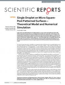
< - - 1 L12 >1 < -2 3 > Fig. 2. Schematic diagram of the ideal separated-beam three-grating interferometer. In the numerical model Lo, = 1.0 m and L12 = L23 = 0.5 m; the gratings have a 0.2-Amgrating period with equal bar and space widths; the source has a Gaussian 12% 1/evelocity distribution centered at A = 0.02 nm; the detector is 25 ,m wide; w = 1000 tm; and the beam-collimating slits are each 20 Am wide (the slit and grating in the xl plane are coincident in z). The interferometer paths shown are those that yield a maximum interference signal and converge in front of the detector.
volution of T2N and
f2N
can be broken up as (we consider
only0 ' j < N) (qf 2 N X f2N)
=
j N-1 E 2Nf 2N + E i-O i-j+i 2N-1 + E2 p 2Nf 2N i=N
Wr-2N
(11)
By usingthe definitionof p2N, it is seen that the last term on the right-hand side of Eq. (11) is identically zero and that the T2N in the first two terms can be replaced by 'I Exploiting the periodicity of f2N and applying the abovementioned observations, we obtain j
(r2N
®f 2N)j = 1itf2N >2 i=O
N-1
+ 2 'itf-i+2N
(12)
i=j+i
so that, with the definition off2N, Eq. (12) is equivalent to Eq. (8) for 0 j < N. Thus the parallel-plane diffraction problem can be calculated with convolutions. For the next two planes in the interferometer, we take the first N elements of T2N and define a new 2N amplitude by using Eq. (10), use the f appropriate for propagation between these two planes to define a new f2N according to Eq. (9), and calculate the new two-plane problem. We continue in this way until all the planes are traversed. To complete the description of the numerical model we now describe the numerical model of the source. An experimental source that obeys assumption (a) in Section 2 has two unrelated parameters: the location of each constituent point source in space and the wavelength distribution (velocity, for particles) or, equivalently, P(k). We choose a method of representing the source whereby these two parameters are included simultaneously in each numerical source point. The source position is divided into bins (in the x0 plane), and a point radiator is randomly assigned to a position within each bin. Each point radiator is then randomly assigned a unique wave number from P(k) and given the appropriate weighting. In agreement 2 with assumption (a) in Section 2, the intensities kp(x.)I for each independent source point are added to obtain the total intensity.
Combining the results of this section completes the model of the interferometer. With the numerical criteria satisfied, the n-plane interferometer calculation can be computed quickly by combining n - 1 between-plane Helmholtz propagation problems and solving each with convolutions, using the method outlined above. The procedure is repeated for each source point. Three fast Fourier transforms are used to perform the convolutions, giving a dramatic reduction in computational time. For an N-sample-point calculation of the two-plane problem, the fast algorithm computes in 0(3 X 2N X log 2N) time, whereas a brute-force calculation of the integral takes O(N2 ) time, as discussed above. The fast algorithm time increases linearly with the number of planes, whereas this quantity is in the exponent for the straightforward bruteforce approach. With N = 106, the fast algorithm for a two-plane problem takes 4 s on a Cray-2. While it is unfair to compare the running time of the fast algorithm with that of a brute-force calculation with this size N [we would not use such a wide experiment that requires such a
1.0 0.8
0.8 -
0.4 U,
0.6 0.0
I-F
49.0
0.4 0.2 0.0
I-
I pp I
50.0 Lim -
r
Lh
_
I
b
I
-400 -200
I
I
0
200
X
400
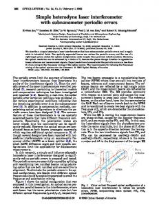
transverse position (gum) Fig. 3. Intensity distribution of the ideal three-grating interferometer at the incident side of the third grating plane, captured by an ideal-point detector. The magnified region is the area in which the experimental detection process takes place. There are sample points every 0.95 nm.
Turchetteet al.
Vol. 9, No. 9/September 1992/J. Opt. Soc. Am. A
large N if we were calculating in O(N2 ) time], the savings in time is a factor of -104.
0.7 -
1605
0.6 0.5-
4.
APPLICATION OF MODEL
We first applied the numerical model to an idealized version of our experimental three-grating atom interferometer, shown in Fig. 2. The spatial intensity distribution on the incident side of the third grating, 10(x3)12, is shown in Fig. 3. The dark areas of the graph are fine period fringes that are due to the interference of two spatially distinct paths; the magnified portion shows the fringes that are unresolved on the larger scale. The suppression of every fourth interferometer order seen in the graph is due to the model's assumption of equal bar and space widths for the gratings, which therefore have no amplitude in the even 106. orders. The calculation uses N We next used the numerical model to determine the effects on the overall intensity and fringe contrast in our three-grating interferometer that resulted from changing certain parameters of the model. First the model examined the depth of field of the interferometer by changing the position of the third grating. In the ideal interferometer the three gratings are separated by equal distances, guaranteeing that the interferometer paths exactly recombine at the plane of the third grating. If the third grating is not in the correct position, the beam recombination will not be exact, and interferometer signal contrast will decline. [Contrast, or visibility, is defined in the standard way as (Imax- Imin)/(Ima + Imin).] Figure 4, a plot of the
interference signal contrast versus a =100(L 2 3/L1 2 - 1) (see Fig. 2), shows that contrast declines with increased misposition. For this application, a detection process mimicking that of the experimental interferometer was used. To detect the interference signal in the experimen-
0.4-
o 0.30o.2 0.1
0.0 -10
10
5
0
-5
percent misposition of third grating (a) Fig. 4. Interference signal contrast versus third-grating misposition (a) for three-grating interferometer with moir6 detection. The dots are computed for an interferometer with a single monochromatic point source; the crosses are computed with the full extended multichromatic source. Positive misalignment is away from the second grating; negative is toward. The solid fit is to the monochromatic point source, and the dashed fit is to the multichromatic extended source. Both are Lorentzian functions and serve only to guide the eye; we attribute no analytic significance to the form.
1 .0
0.8 U,
6)
.6)
0.6 2.5 gm
0.4 0.2
tal interferometer, the spatial intensity pattern at the
final plane, 1k(x3)I 2, is masked by the third grating in a moir6 detection scheme for various transverse positions of the third grating. Because the interference signal has a
0.0 -400 -200
0
200
400
period equal to the grating period, the final intensity
transverse position (gm)
through the third grating on the detector is a sinusoidal function of the third grating position. From this sinusoidal signal the contrast values of Fig. 4 were calculated. The simulation was run for two types of numerical source: the first was a single monochromatic point source (to save computational time), and the second was the multichromatic extended source described in Section 3. It is clear from Fig. 4 that the proper characterization of the source is important. From further tests it was determined that the spatial extension of the source plays a much greater role in reducing contrast in a misaligned interferometer than does the 12% multichromicity. Next we used the numerical model to examine the effects of changing the collimation slit widths. With narrow
Fig. 5. Same as Fig. 3 for wide collimating slits (source: 200 gm; first grating: 80 ,um). Note the good contrast in the interference signal.
slits the interferometer has distinctly separated paths. However, when the slit sizes are increased, the beam widths become large enough that there are no separated paths. We applied the model to the case in which the collimation slits of our interferometer were 200 ,um for the source slit and 80 ,um for the first grating slit and found
that there were still high-contrast fringes formed, as shown in Fig. 5. With a moir6 detection scheme included, the contrast is 0.18. In the wide slit mode the collimation
is insufficient to separate the paths in either position or angle, and the interferometer can be well described by the techniques of Fourier imaging. In this regime discussion has been limited to certain planes because of the simplification in the analytic treatment; however, this is clearly not a necessary restriction for our numerical model. 5.
CONCLUSIONS
We have developed a computationally efficient numerical model of a multiple-grating interferometer that yields high-resolution results. The results of the model proved useful in making design choices for our interferometer. For example, we were uncertain as to the required grating spacing accuracy; the results described above prove that an easily achievable accuracy of 1%is sufficient. We also were unsure of the quality of fringes for our interferometer with a multichromatic extended-source run in a mode lacking separated beams. The model demonstrated that
1606
J. Opt. Soc. Am. A/Vol. 9, No. 9/September 1992
we may run wide, unseparated beams and still expect good contrast. In addition, we used this model to predict the performance of a cylindrical zone-plate lens that we recently fabricated and tested.' 9 Because our model treats a general optical problem, it is applicable to many other interference experiments. Double-slit experiments, single-grating diffraction, and focusing with zone plates are a few of the many experiments to which our model may be applied. If the waves obey the Helmholtz equation, the planes are parallel, and the diffracting elements can be treated as simple transmission or phase screens, the model is accurate. We have presented the model in a regime that allows for convenient simplifying approximations to the theory of the multiplegrating interferometer. We have shown that these approximations are well justified in our atom interferometer and that they lead to a computationally useful form for the propagation integral. The model could be extended to include regimes in which the derivative cannot be neglected. The resulting, more complex calculation would require twice as many operations plus a derivative at each plane.
For separated-beam interferometers and many other devices, dimensions are such that the analytic approximations that we employ to simplify the problem will often be met, making the model a quick and a useful tool.
ACKNOWLEDGMENTS
We thank John Clauser, Anton Zeilinger, Jene Golovchenko, and Michael Haggerty for stimulating conversation, and we thank N. Davidson for helpful comments on this paper. This study was supported by Office of Naval Research contract N0014-89-J-1207, U.S. Army Research Office contract DAAL03-89-K-0082, and Joint Services Electronics Program contract DAAL03-89-C-0001. *Present address, Department of Physics, California Institute of Technology, Mail Code 12-33, Pasadena, California 91125.
C. E. Ekstrom,
Pritchard, 'An 66, 2693-2696 2. 0. Carnal and with atoms: a 66, 2689-2692 3. D. W Keith,
Q. A. Turchette,
and D. E.
interferometer for atoms," Phys. Rev. Lett. (1991). J. Mlynek, "Young's double-slit experiment simple atom interferometer," Phys. Rev.Lett. (1991).
M. L. Shattenburg,
4. A. Faulstich, 0. Carnal, and J. Mlynek, "Optics with a supersonic atomic beam," in Proceedings of the International Workshop on Light Induced Kinetic Effects on Atoms, Ions, and Molecules, L. Moi, ed. (ETS Editrice, Pisa, Italy, 1991), p. 183.
5. M. Reinsch and J. Clauser, "Grating-sequence atom interferometers," Bull. Am. Phys. Soc. 36, 1312 (A) (1991). 6. P. L. Gould, G. A. Ruff, and D. E. Pritchard, "Diffraction
of
atoms by light: the near-resonant Kapitza-Dirac effect," Phys. Rev. Lett. 56, 827-830 (1986). 7. P. J. Martin,
B. G. Oldaker,
A. H. Miklich,
and D. E.
Pritchard, "Bragg scattering of atoms from a standing light wave," Phys. Rev. Lett. 60, 515-518 (1988). 8. F. Riehle, T. Kisters, A. White, J. Helmcke, and C. J. Borde, "Optical Ramsey spectroscopy in a rotating frame: Sagnac effect in a matter-wave interferometer," Phys. Rev. Lett. 67, 177-180 (1991).
9. M. Kasevitch and S. Chu, 'Atomic interferometry using stimulated Raman transitions," Phys. Rev. Lett. 67, 181-184 (1991).
10. A. Zeilinger, Atominstitut, Schuettel Strasse 115, A-1020 Wien, Austria (personal communication, 1989); J. Clauser, Department of Physics, University of California, Berkeley, Berkeley, Calif. 94720 (personal communications, 1989 and 1991).
11. J. Clauser and M. Reinsch, "New theoretical and experimental results in Fresnel optics, with applications to matter-wave and x-ray interferometry," to be published in Appl. Phys. B. 12. The Kirchhoff assumptions are that 40and 0l/an vanish everywhere except on the openings and 0 and adl/anafter the openings have their incident values. We accept the mathematical inconsistencies of the Kirchhoff approximation to the diffraction integral. In the.analysis that follows, we employ additional approximations that make it clear that a more rigorous approach to the diffraction problem would lead ultimately to the same conclusion. See, for example, J. D. Jackson, Classical Electrodynamics Sec. 9.8.
(Wiley, New York, 1975),
13. D. W Keith, 'An interferometer for atoms," Ph.D. dissertation (Massachusetts Institute of Technology, Cambridge, Mass., 1991). 14. See Jackson. 2
15. R. P. Feynman and A. R. Hibbs, Quantum Mechanics and Path Integrals
(McGraw-Hill, New York, 1965).
16. The previous research is in J. A. Leavitt and F. A. Bills, "Single-slit diffraction pattern of a thermal atomic potassium beam," Am. J. Phys. 37, 905 (1969). Our results are reported in Q. A. Turchette, S. B. thesis (Massachusetts Institute of Technology, Cambridge, Mass., 1991).
REFERENCES AND NOTES 1. D. W Keith,
Turchetteet al.
H. I. Smith,
and D. E.
Pritchard, "Diffraction of atoms by a transmission grating," Phys. Rev. Lett. 61, 1580-1583 (1988).
17. See, for example, J. W Goodman, Introduction to Fourier Optics (McGraw-Hill, San Francisco, Calif., 1968), Chap. 4. 18. The convolution theorem states that F.T.(a 0 b) = F.T.(a) x F T.(b), where F.T. is the Fourier transform operation and is the symbol for convolution.
See, for example, E. 0. Brigham,
Fast Fourier Transform (Prentice-Hall, EnglewoodCliffs, N.J., 1974). 19. D. W Keith, R. J. Soave, and M. J. Rooks, "Free-standing gratings and lenses for atom optics," J. Vac. Sci. Technol. B 9, 2846-2850 (1991).