service-oriented software systems, and relies on an ontology to provide domain experts with ..... are best explained in behavioral terms: see Section 8. 7.1 ... LoopingActivityU may repeat a number of times determined by the Condition field,.
A Modeling Language for Activity-Oriented Composition of Service-Oriented Software Systems Naeem Esfahani, Sam Malek, João P. Sousa, Hassan Gomaa, and Daniel A. Menascé Department of Computer Science George Mason University {nesfaha2, smalek, jpsousa, hgomaa, menasce}@gmu.edu
Abstract. The proliferation of smart spaces and emergence of new standards, such as Web Services, have paved the way for a new breed of software systems. Often the complete functional and QoS requirements of such software systems are not known a priori at design-time, and even if they are, they may change at run-time. Unfortunately, the majority of existing software engineering techniques rely heavily on human reasoning and manual intervention, making them inapplicable for automatic composition of such software systems at run-time. Moreover, these approaches are primarily intended to be used by technically knowledgeable software engineers, as opposed to domain users. In this paper, we present Service Activity Schemas (SAS), an activity-oriented language for modeling software system’s functional and QoS requirements. SAS targets service-oriented software systems, and relies on an ontology to provide domain experts with modeling constructs that are intuitively understood. SAS forms the centerpiece of a framework intended for user-driven composition and adaptation of service-oriented software systems in a pervasive setting. We provide a detailed description of SAS in the context of a case study and formally specify its structural and dynamic properties. Keywords: Requirements Modeling, Domain Specific Modeling Languages, Model Driven Development, Autonomic Computing, Pervasive Systems
1
Introduction
Software systems are increasingly permeating a variety of domains, including medical, industrial automation, defense, and emergency response. The growth of service-oriented software systems and the emergence of new standards have made it possible to develop pervasive systems that were not even conceivable a few years ago. In particular, the decoupling of service providers from consumers and the flexibility of dynamically discovering and binding to services have facilitated the development of software systems intended for execution in smart spaces. The proliferation of portable and embedded computing devices and the recent advances in wireless network connectivity have further made the service-oriented architecture (SOA) paradigm a viable option in such settings. Web Services [1] have also played a crucial role in enabling interoperability and alleviating integration challenges in pervasive settings.
Domain experts and end-users increasingly rely on such systems for their day to day activities. The software deployed in such settings needs to deal with the inherently dynamic and unpredictable nature of pervasive environments. Finally, the functional requirements of such software systems are often not completely known at design-time, and even if they were, they may change at run-time. These characteristics have forced the designers of such systems to deal with two emerging and increasingly important classes of daunting challenges: (1) rapid composition of software systems at run-time based on the users’ changing needs, and (2) autonomous adaptation of the software system at run-time to satisfy the system’s functional and non-functional requirements. However, the majority of existing software engineering techniques for representing, analyzing, and composing software systems rely heavily on human reasoning and manual intervention, making them unwieldy for use in this setting. Moreover, these approaches are primarily intended to be used by technically knowledgeable software engineers, as opposed to domain experts that use such systems on a daily basis. Motivated by the aforementioned challenges, we have developed a framework entitled Self-Architecting Software Systems (SASSY) [2]. SASSY enables autonomic composition and adaptation of service-oriented software system based on the domain users’ requirements. To that end, domain users express their functional and Quality of Service (QoS) requirements in an intuitively understood visual modeling language. SASSY in turn automatically generates an architectural model that satisfies the system’s requirements, and deploys it through discovery and coordination of available services. Moreover, SASSY continuously monitors the running system and, if necessary, adapts the architecture and running system to ensure the user’s requirements are satisfied throughout the system’s execution. In this paper, we present Service Activity Schemas (SAS), an activity-oriented language for modeling the user requirements in the SASSY framework. SAS allows for the representation of both functional and QoS requirements in terms of modeling constructs that are intuitively understood by domain experts. The SAS modeling notation relies on a domain ontology that clearly specifies the semantics of the domain entities and their interrelationships. Unlike existing low-level service coordination languages (e.g., BPEL [3] semantic BPEL[4], JOpera [5]) and software modeling languages (e.g., UML [6], ADL [7]), the language is intended to be usable by domain experts. While SAS is motivated by business process modeling languages (e.g., BPMN [8]), it represents a departure from them as it codifies the system requirements in a manner that enables the automatic generation of executable pervasive SOA software systems. We have developed an implementation of SAS as a Domain Specific Modeling Language (DSML) on top of the Generic Modeling Environment (GME) [9]. The static and dynamic characteristics of the language are formally specified using the GME meta-models and Z notation [10], respectively. Our experiences with applying the language and environment to pervasive SOA software systems have been very positive. In all cases, the language proved to be both usable and rich enough to accurately represent the domain expert’s requirements. A subset of one of these systems for a fire emergency application is described throughout this paper.
The remainder of the paper is organized as follows. Section 2 introduces the SASSY framework and describes the role of SAS in the overall scheme. Section 3 presents the related work. Section 4 describes a case study, which is used to introduce the language in Section 5. Section 6 details the process of using the language for the composition of service-oriented software system. Sections 7 and 8 present the structural and dynamic semantics of SAS, respectively. Finally, the paper concludes with an outline of our future work.
2
The SASSY Framework
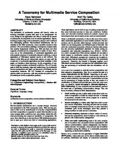
SASSY [2] is a model-driven framework for composing SOA software systems (see Fig. 1 for an overview). The domain expert specifies the functional and QoS requirements using the SAS language, which is the focus of this paper. With the help of a domain ontology, these requirements are translated into the system’s base software architecture. The domain ontology provides the means for unambiguously distinguishing different concepts and elements, which as outlined further below facilitate discovery of services and resources in support of activities. We assume the domain ontology is created and maintained by a consortium of domain experts, who specify the various domain activities and concepts, including the properties of respective services that realize them. Examples of such ontology and directories provided by the US government for various domains can be found at [11]. After generating the base architecture, SASSY instantiates the architecture by discovering the required services and selecting the ones that maximize a global utility function that depends on the system’s QoS requirements. SASSY generates alternative architectures by exploring and applying architectural patterns that increase the utility. For instance, in a situation where a service provider’s availability causes the utility to be reduced, SASSY may employ a replication pattern to compose two services in a way that one can be used as a hot standby for the other. At run-time, Domain Expert SASSY monitors the Service Activity Schema services and computes Base Software Architecture Generator the value of the global Domain Ontology Base Software Architecture utility function. When it is reduced by a given U (r) Service Discovery threshold, SASSY reOptimal Service Selection architects the system Utility functions r and adapts it Yes No QoS met? accordingly. Similarly, Critical SSS Determination SASSY re-architects Architectural the system when the Alternative Architecture Generator Patterns domain experts change Executable Software System the system requirements, and thus SASSY Run-time Support System evolves the system. Fig. 1. An overview of SASSY framework. R
3
Related Work
There are fundamentally two schools of thought concerning the modeling of activities: one focuses on the modeling of human activities, the other focuses on the modeling of workflow of computational and/or business processes. The first has its roots in psychology, going back to Leont’ev’s modeling of craftsmen activities [12], which inspired design approaches in human-computer interaction based on the modeling of user activities (e.g., [13]). This approach recognizes that users carry out actions to achieve their goals, but that the specific actions and their ordering is adapted to the material conditions of execution, that is, it cannot be prescribed a priori: a concept called situated action. In contrast, workflow modeling prescribes a concrete flow of actions to be followed. Recently, there has been considerable work on Business Process Execution Language (BPEL [3]), and Business Process Modeling Notation (BPMN [8]). BPEL is an executable business process language, serialized in XML, to support programming in the large (e.g., see [14] for an overview and formal semantics and [4] for application of ontology to make BPEL accessible in semantic level). BPMN [8] is a business process modeling language, intended to be used by domain experts in a variety of domains. BPMN has three major drawbacks: (1) it is a general purpose language and semantically loosely defined, making it difficult to automatically generate executable models from it; (2) it does not support specification of QoS requirements; and (3) it is not suitable for pervasive settings as it lacks support for long living activities. Our modeling approach in SASSY combines the adaptability of situated action, for dealing with uncertainty and emergent behaviors in domains such as emergency response, and the efficacy of workflow, for coordinating the behaviors of complex software systems. In general, the development of visual modeling languages and tools for supporting the design of complex service-oriented systems is lagging behind the development of the underlying technology. Among the existing works, JOpera [5] is most closely related to our language. JOpera provides a workflow modeling language for representing the transformation of data among services. However, unlike SAS, the language provided by JOpera is very low-level and not intended for use by domain experts. Moreover, JOpera does not provide support for modeling QoS requirements, long living activities, and distinguishing local activities from services. Finally, UML [6,15] is a commonly used notation for the visual modeling of today’s software systems. UML’s diagrams provide a standard notation for representing the various structural and behavioral aspects of a system’s software. Several approaches extend UML’s notation via stereotypes [16,17]. However, using UML to visualize the requirements of a software system has several drawbacks: UML’s diagrams are relatively static; they do not consider services as first-class modeling entities; do not provide native support for representing and visualizing the parameters that affect the system’s QoS properties; and are not semantically constrained to enable automatic composition of SOA software. Moreover, UML is not aligned with SASSY objectives, as it is geared to software engineers, instead of domain experts.
4
Case Study
We use a software system, called Fire Emergency Response System (FERS), for describing the language and demonstrating its properties throughout this paper. FERS is developed internally and motivated by existing standards [11]. It targets SOAenabled smart spaces and is intended for use by emergency response organizations to automatically detect, respond, and manage fire emergencies. An FERS school is equipped with two types of sensors: smoke detectors and fire sprinklers. There may be many smoke detectors and fire sprinklers throughout a school. A sensor exposes a web service that provides operations for accessing its status and controlling it. For instance, a fire sprinkler service provides operations that allow other entities in the system to turn the sprinkler on/off. A school also exposes a service that provides profile information, such as the name of the school, location, number of students, and hours of operation. An FERS fire station has a fire monitoring service (FMS) that keeps track of all the sensors in the schools. A fire station also has several fire engines. Once smoke is detected by the FMS, it uses the fire station’s fire dispatch service to dispatch the closest smart fire engines to the scene. In order to determine the number of required fire engines that need to be dispatched, the dispatch service uses a heuristic based on the information (e.g., number of students, size of the school, and hours of operation) made available by the school's profile service and the number of smoke sensors that have detected smoke. A fire engine constantly communicates its status and progress to the station's dispatch service. As soon as the fire has been extinguished, the system resets the smoke detectors, turns off the fire sprinklers, and orders the fire engines to return to base.
5
Language Overview
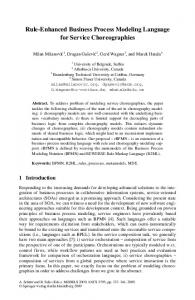
This section introduces the SAS language through a small subset of the FERS system. In Sections 7 and 8, we revisit the language constructs and precisely define their semantics. Fig. 2 shows some of the modeling constructs available in the SAS language. Events are messages exchanged between two separate entities. Gateways manage the flow of control within an entity. Some of the supported gateways include InclusiveGateway (Conditional-Or), ExclusiveGateway (Switch), and ParallelGateway (Fork and AndJoin). The language distinguishes local Activities from ServiceUsages, i.e., activities performed by external entities (another organization). An underlying assumption in our work is that activities and service types are defined in a domain ontology, and commonly understood by domain experts. SAS also supports hierarchical composition through the notion of Sub-SAS. Activities, Sub-SASs, and ServiceUsages are represented by rectangles with round corners. A Sub-SAS is delineated with a plus sign, for bringing up the internal composition, and a ServiceUsage with a server icon.
Communication with a service is via Input and Output events, while communication with a Sub-SAS is via StartLink and EndLinks. An SAS model is a graph where nodes correspond to activities and services that are coordinated to realize some functionality. In fact, as detailed in Section 6, an SAS may realize the functionality of a service type defined in the ontology. Fig. 2b shows an SAS model that realizes the dispatching service of FERS. When a dispatch message arrives, dispatching service calculates which fire engines should be assigned to the incident. The SAS is divided into two parallel sequences through a ParallelGateway, which behaves as a fork/join. The first path queries the School service where the smoke detector is located to get an estimate of the number of people in the school. The second path uses the createInc interface of the MissionManager Sub-SAS to create a record for the incident. When both the incident and occupancy messages have arrived, they are joined by a ParallelGateway into a single sequence. assignFE is a looping activity that uses this information to determine which fire engines (FE), if any, should be dispatched. When the dispatching service receives a normalcy message, it uses the cancelMis interface of MissionManager to send a callBack message to command the fire engines to return to base. Throughout the mission each fire engine periodically reports its status to the dispatch service by sending a report message. Fig. 2c shows the association of a QoS requirement with a path through the dispatching service SAS. A QoS requirement is specified via a Service Sequence Scenario (SSS). In this case, the response SSS indicates that the School service should respond to a request made by the coordinator within a pre-specified time. Section 7 describes how such QoS requirements are specified as attributes of an SSS.
Fig. 2. SAS for dispatch service: a) language constructs, b) basic flow, and c) response SSS is selected.
An SAS may be made available for reuse as a service, a Sub-SAS, or both. An SAS exposed as a service may be used by external organizations for constructing their own SASs. Similarly, a Sub-SAS allows for hierarchical composition of SASs, and enables reuse within the same organization. The details of SAS reuse are further discussed in Section 6. Note that since one of our objectives has been to make the SAS language usable by domain experts, the coordinator is implicitly defined. In other words, an SAS model represents the coordination between internal activities and external services. This differs from a software design perspective, where a coordinator component is explicitly delineated and separated from the rest of the system. Our approach is compatible with existing business process modeling languages (e.g., BPMN [8]) that are also intended for use by domain experts.
6
Building Service-Oriented Systems with SAS
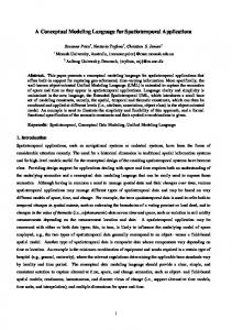
In our work we assume each domain has either a standard body or an organization in charge of defining the domain ontology. For example, in the emergency response domain a government authority typically defines the corresponding ontology (e.g., [11]). SAS enables an organization to realize a service type defined in the ontology, and make it available for external use by registering it in a service directory (e.g., UDDI [18,19]). In this way each organization retains its autonomy. At the same time, the ontology enables interoperability and integration among the various organizations, and forms them into a coherent task force. We further elaborate on the details of this process below. Defining a service type in the ontology consists of specifying (1) the service’s interfaces, and (2) the service’s interaction protocol. A service type’s interfaces correspond to its input and output messages, similar to the information provided in a WSDL [18]. A service type’s interaction protocol describes the relationship between the service’s interfaces. It indicates the output messages and the order they are generated when the service receives a particular input. For defining the interaction protocol a subset of the SAS constructs (i.e., Input, Output, Gateway, and Flow) is used. Fig. 3a shows the interaction protocol for the FE service (recall example of Fig. 2b). This interaction protocol specifies that a service of FE type receives return and missionSend messages and as result of that generates one or more report messages. The flow from the gateway to itself in Fig. 3a specifies that in response to one request message several report messages can be generated. Organizations query the ontology for a service type’s definition to determine how an instance of it can be used in their own SAS. An organization that intends to provide an instance of a service type creates a corresponding SAS as follows: replaces the Inputs and Outputs messages with StartLink and EndLinks, respectively; and provides an implementation for each of the service’s interfaces that comply with its interaction protocol. The constructed SAS is then made available to other organizations by registering it in a service directory.
Fig. 3. Fire engine (FE) service: a) interaction protocol specification, and b) an SAS implementing the service specification.
Fig. 3b illustrates the corresponding SAS for the interaction protocol of the FE service shown in Fig. 3a. As a result of the FE service receiving a return order, the fire engine goes back to its base station. The location of base station is a parameter in the return message that is delivered to goToLocation activity. While on its way back, the goToLocation activity periodically sends a report message, which as you may recall from recall Fig. 2b updates the fire station of the vehicle’s current status. When the FE service receives the missionSend message, the vehicle is directed to go to the fire scene, and as before continuously sends updates of its current status. When the fire engine arrives, it checks whether there is a real fire or not. If it is a false alarm, the smoke sensors are turned off. Otherwise, the sprinklers are turned on, and the FE is directed to extinguish the fire. Meanwhile, the FE continuously sends report messages to update the fire station of its progress. Note that activities such as goToLocation, fightFire, and checkFire may either be automatically enabled, or rely on a firefighter to manually check the existence of a fire and inform the system through a user interface. In other words, we model the humans through the user-interface (itself a service) they use for the interaction with the system. The domain experts are advised to be careful with the specification of QoS goals (SSS) involving such activities, since the ability to satisfy such QoS properties relies on the humans, whose behavior cannot be controlled by SASSY. The SAS depicted in Fig. 3b is only one implementation of the FE service. Other organizations may provide their own implementation of FE using different SASs. The only restriction is that the SAS needs to adhere to the interface definition and the interaction protocol (i.e., Fig. 3a) described in the ontology. Note that our approach does not prevent organizations from providing an implementation of a service type using other more traditional techniques (e.g., programming languages, BPEL).
7
Structure of SAS
The linguistic structure of SAS is defined using the meta-model provided by the Generic Modeling Environment toolkit (GME) [9]. GME is a general purpose modeldriven engineering environment that enables the development of domain-specific
modeling languages. Just as formal grammars define the structure of valid sentences for textual languages, meta-models play a similar role for graphical languages. GME has the ability to interpret a given meta-model and automatically build a modeling environment that enforces the structural rules. The meta-modeling language supported by GME is a stereotyped variant of UML, which we explain below, as needed. Fig. 4 shows the meta-model for SAS divided into three parts, for readability: graph, service, and QoS. Starting with graph, an SAS model contains Nodes, ServiceUsages, and Flows between those. Nodes may be either ActivityUsages or Gateways, which in turn may be Parallel, Inclusive, or Exclusive. We elaborate on each of these below. Furthermore, hierarchical decomposition is supported by allowing an SAS to contain other SASs (i.e., a Sub-SAS). A parent SAS interacts through StartLink and EndLink nodes, which act respectively as input and output interfaces to a child SAS. Ultimately, a number of SASs may be included in a hierarchical structure of folders containing the Requirements for a system. With respect to the stereotypes that annotate this meta-model, GME defines Model which corresponds to a diagram, Set for defining subsets of objects within a diagram, Atom which has a graphical representation, and Connection, represented as a line between two atoms. Additionally, Reference provides a mechanism to describe several usages of a single definition. First class object (FCO) is a super type of the above used for organizing the meta-model, and has no associated graphical representation of its own, e.g., SAS is a Model, an Exclusive gateway is an Atom, and Gateway is an FCO. A Flow represents a line between two GenericNodes: the source and destination of the flow. A Flow carries data from between two nodes. The Condition field of a Flow determines whether a particular data can traverse that Flow. The Mapping field of a GenericNode specifies the transformation of data as it enters and exits a node. This transformation describes which data is passed into the node, and which data is returned from the node. Since the transformation of data is a common feature of several SAS constructs (e.g., Gateways, ActivityUsages, Links), it is modeled as an attribute of GenericNode. Gateways play a key role in coordinating the behavior of an SAS, and are best explained in behavioral terms: see Section 8. 7.1
Services and Activities
ServiceUsage and ActivityUsage constitute the basic functional elements of an SAS. While an activity is carried out internally by the component, e.g., a call to a system library, a service is requested to another component, possibly across the network. A LoopingActivityU may repeat a number of times determined by the Condition field, before completion. An Activity may have a return value which can be specified using Result. The Results are added to the outgoing data. Both ActivityUsage and ServiceUsage are stereotyped with Reference, which allows for referring to existing Activity and Service definitions. Such definitions exist in ActivityDirectory and ServiceDirectory, respectively, which are populated based on the information available in a domain ontology, and may be consulted by the domain experts while designing an SAS.
Fig. 4. Meta-model for SAS in three parts: a) graph, b) service, and c) QoS.
Fig. 4b shows the meta-model for services. A ServiceDirectory is a Folder containing multiple Service definitions. A Service is a Model, that is, it has an associated diagram containing Input and Output interface nodes. The role of the latter is similar to the role of the StartLink and EndLink interface nodes: to facilitate the interaction between other constructs in the SAS and the internals of the particular box (a service or sub-SAS, respectively). Outputs are responsible for returning the Result from the Service. The Proxies that annotate the meta-model are simply a mechanism provided by GME for referring to objects defined in other parts of the meta-model. 7.2
Service Sequence Scenarios and QoS
Service Sequence Scenarios (SSS) are used to represent the user’s QoS preferences. For that, each SSS defines a path through the SAS (recall Fig. 2c). In the meta-model, we represent an SSS path as a set of GenericNode and Flow constructs. Naturally, an SAS may contain several SSS sets, each modeling a separate QoS concern. Fig. 4c shows the internal structure of an SSS, which consists of QoSMetric and SSSUtility for defining the QoS and the user’s preferences, respectively. QoSMetric may be typed as Plain or Aggregatable. Values of Plain QoS cannot be aggregated into more complex measures, e.g., a measure of Security in a qualitative scale could be: Low, Medium, High. In contrast, the values of Aggregatable ones may
be combined using aggregation operators, such as summation or mean, in the case of numbers. For example, a measure of throughput may be derived from measures of response time and parallel capacity. Fig. 4c shows ResponseTime as an Aggregatable measure, but the approach is not limited to a predetermined set of metrics. An SSSUtility contains one or more QoSMetrics and provides a Function, which returns the utility associated with a given level of QoSMetric(s) for a user. Finally, an SAS contains a global utility function, called SASUtility. It includes a set of SSS and is used to specify the users’ preferences in resolving the trade-offs among multiple SSS constructs. Its Function field specifies the relationship between the contained SSS constructs, i.e., quantifies the impact of achieving QoS specified in the SSSUtilities on the value of the global utility (SASUtility).
8
Behavior of SAS
The model presented in this section complements the meta-model in section 7 by clarifying the behavior of the different kinds of Nodes (Fig. 4). Similar to BPMN and Petri Nets [20], this model is based on the notion of execution token. Specifically, the purpose of the behavior model herein is to answer the question: if a token is presented as an input to a node, how does that node process the token? By specifying the behavioral semantics of the nodes in SAS, this model offers a precise guideline for the automatic generation of implementation code (i.e., coordination logic) from SASs. We selected Z [10] as a convenient notation to express the behavior of SAS constructs. Z builds on set theory and offers constructs such as base sets, functions, schemas, and operations, which are explained by example, below. Tokens and nodes are modeled as elements of base sets Token and Node, respectively. At the implementation level, tokens correspond to messages circulating in the system, possibly with a data payload, and nodes correspond to the functional elements that process those messages and decide what to do next. By modeling tokens as elements of a base set, they are individually distinguishable, but their internal structure is abstracted out. The same holds for nodes. The left side of the model below shows the definitions for these base sets, an enumeration, Type, and a schema, SAS: [Node,Token] Type ::= In | Out | Start | End | ExclusiveGW | InclusiveGW | ParallelGW | Activity | LoopingActivity »SAS___________ ÆTokens : P Token –_____________
ÆInput: Node x P Token f P Token ÆLoop: Node x P Token f P Token ÆMerge: Node x P Token f P Token ÆGenerate: Node x P Token f P Token ÆAll: Node x P Token f P Token ÆPossible: Node x P Token f P Token ÆOnePoss: Node x P Token f P Token
The Type enumeration captures the type of node as defined in section 7: activities, start and end links of Sub-SASs, etc. The set of tokens currently in circulation characterizes the execution state of an SAS. The schema SAS above holds the Tokens set as a state attribute. This set is modified by operations that capture the behavior of the different kinds of nodes. Consumed tokens are removed from Tokens, while the produced ones are added to it. To help specify the behavior of nodes, a number of
functions are defined on the right side of the model excerpt above. These functions can be grouped into three categories: query, generate, and replication functions. Input, Loop, and Merge query the availability of tokens at the input of nodes. These three functions take two arguments: a node of interest and the set of tokens currently in circulation in the SAS. Specifically, Input returns (a set containing) a token that is present at an input flow of the node, if such a token is available among the ones currently in circulation in the SAS (passed as the second argument). If not, Input returns the empty set. Loop returns (a set containing) a token, if the node is a LoopingActivity that currently holds a token, and if its associated looping condition remains true. Merge returns a set of tokens, one token taken from each of the inputs leading up to the node, provided each of the inputs has at least one token available. The Generate function abstracts out the transformations of the data payload of tokens that may occur within nodes. Specifically, given a node and a set of tokens at the node’s input, Generate returns the token produced by the node. All, Possible, and OnePoss are replication functions. They take a newly generated token and a node, and place copies of the token on the node’s output flows. Replication functions take into account the constraints on the flow of tokens, as represented by the Condition in the Flow object in Fig. 4a. Specifically, Possible places a token on each of the output flows where the associated condition holds, while OnePossible does the same for only one of the output flows, selected nondeterministically. For nodes that do not impose constraints on the output flows, such as the ParallelGateway, the All function places a new token on each output flow. 8.1
Services and Sub-SAS
The SAS initialization function and the specifications of Input, Out, and Link are: »SASInit___ »InputNode__________________ ÆSAS' ÆDSAS; n?: Node; t?: Type «_____ «______ ÆTokens' = 0 Æt? = In ¶ Tokens' = Tokens \ Input(n?,Tokens) –_______ –_______________________ »OutputNode__________________________ ÆDSAS; n?: Node; t?: Type «________ Æt? = Out ¶ Tokens' = Tokens U Possible(n?,Generate(n?, 0)) –________________________________ »LinkNode___________________________ ÆDSAS; n?: Node; t?: Type; i: P Token «________ Æ(t? = Start v t? = End) ¶ i = Input(n?,Tokens) ÆTokens' = (Tokens U Possible(n?,Generate(n?,i))) \ i –________________________________
SASInit specifies that initially there are no Tokens inside the SAS. A Link could be considered an interface of an SAS that connects its constructs to those outside of it. A Link passes a subset of the data on an arriving Token to the output Token. A StartLink
does this on Tokens received from the outside of an SAS, while the EndLink does this on the Tokens leaving an SAS. Note that a sub-SAS shares the same set of Tokens with the parent SASs. As you may recall from Section 6, an SAS may expose its interfaces as services, in which case the run-time environment (i.e., the coordination engine) provides the inputs to its StartLinks and collects the outputs at its EndLinks. The In and Out are the interfaces of a ServiceUsage (see Fig. 4b), and hence they serve as destination and source of tokens, respectively. The run-time environment transfers the Tokens between the SAS and external services. 8.2
Gateways
Gateways synchronize activities by forking and joining several threads of activities. The ParallelGateway requires all the inputs to arrive (And-join) and activates all the output flows (fork) at the same time. When an input flow is activated, the InclusiveGateway (Conditional-Or) activates a subset of the output flow. For an outgoing flow to be activated, the condition specified on the flow must be satisfied. On the other hand, the ExclusiveGateway activates the first outgoing flow that has its condition satisfied. The outgoing sequence that is activated is selected nondeterministically. The join semantic for both the InclusiveGateway and ExclusiveGateway are the same. The behavior of ExclusiveGateway and InclusiveGateway, which are the main constructs for enforcing conditions in forking and joining, are specified as follows: »ExclusiveNode_________________________ ÆDSAS; n?: Node; t?: Type; i: P Token «________ Æt? = ExclusiveGW ¶ i = Input(n?,Tokens) ÆTokens' = (Tokens U OnePoss(n?,Generate(n?,i))) \ i –________________________________ »InclusiveNode_________________________ ÆDSAS; n?: Node; t?: Type; i: P Token «________ Æt? = InclusiveGW ¶ i = Input(n?,Tokens) ÆTokens' = (Tokens U Possible(n?,Generate(n?,i))) \ i –________________________________
The ExclusiveGateway consumes the available input and generates a token for one of the possible output flows. The InclusiveGateway does the same thing except it generates a token for all the output flows where the associated condition holds. Finally, the behavior of the ParallelGateway is: »ParallelNode__________________________ ÆDSAS; n?: Node; t?: Type; m: P Token «________ Æt? = ParallelGW ¶ m = Merge(n?,Tokens) ÆTokens' = (Tokens U All(n?,Generate(n?,m))) \ m –________________________________
The ParallelGateway merges all of the input flows and produces tokens for all of the outgoing ones, regardless of the conditions specified on the outgoing flows. If one of the input tokens is not available, ParallelGateway does nothing (i.e., it does not consume or generate tokens). 8.3
Activities
The Activity operation captures the behavior of ActivityUsage nodes, and is very similar to the Link operation. The only difference is that the Generate function for Activity may add new data (i.e., result of the activity) to Tokens. A Looping activity is an extension of a regular activity. It queries for an available token as follows: it first uses the Loop function to find any available tokens inside the Looping activity to consume, when there are no more tokens available in the activity, it uses the Input function to consume tokens from the inputs. These concepts are specified as follows: »ActivityNode__________________________ ÆDSAS; n?: Node; t?: Type; i: P Token «________ Æt? = Activity ¶ i = Input(n?,Tokens) ÆTokens' = (Tokens U Possible(n?,Generate(n?,i))) \ i –________________________________ »LoopingNode__________________________ ÆDSAS; n?: Node; t?: Type; i,l: P Token «________ Æt? = LoopingActivity ¶ i = Input(n?,Tokens) ¶ l = Loop(n?,Tokens) Æ(l Î 0 ¶ Tokens' = (Tokens U Possible(n?,Generate(n?,l))) \ l) v Æ(l = 0 ¶ Tokens' = (Tokens U Possible(n?,Generate(n?,i))) \ i) –________________________________
9
Conclusion
The emergence of SOA-enabled systems in pervasive settings calls for major advances in the software engineering methods currently employed. In this paper, we presented SAS, a novel visual modeling language intended to alleviate the existing shortcomings by automating the composition of such systems. SAS relies on a domain ontology to allow an expert specify the system’s functional and QoS requirements using commonly understood terminology. The formal specifications of the structural and behavioral semantics of SAS provide a precise guideline for the automatic generation of a system’s architectural model and executable code (i.e., coordination logic), respectively. Unlike the existing software design languages (e.g., UML [6], ADLs [7]), SAS is intended for use by domain experts, as opposed to software engineers. To that end, the language is motivated by existing business process modeling languages (e.g., BPMN [8]), which are commonly used by domain experts. However, in contrast, SAS codifies
the software requirements in a manner that enables the automatic composition of service-oriented systems. SAS is part of an ongoing research effort on Self-Architecting Software Systems (SASSY) framework [2]. SAS models have been used in SASSY to successfully compose service-oriented system. Some of the ongoing research include, automatically finding the optimal architecture with respect to QoS objectives specified in SAS models, adaptation of a running system in response to environmental changes, and evolution of a system due to changes in the SAS models. Acknowledgments. This work is partially supported by grant CCF-0820060 from the National Science Foundation.
References 1. W3C Web Services, http://www.w3.org/2002/ws/ 2. Malek, S., Esfahani, N., Menascé, D.A., Sousa, J.P., Gomaa, H.: Self-Architecting Software Systems (SASSY) from QoS-Annotated Activity Models. In: ICSE 2009 workshop on Principles of Engineering Service Oriented Systems (PESOS 2009), Vancouver (2009) 3. OASIS WS-BPEL ver 2.0, http://docs.oasis-open.org/wsbpel/2.0/OS/wsbpel-v2.0-OS.html 4. Nitzsche, J., Wutke, D., Van Lessen, T.: An ontology for executable business processes. In: Proceedings of the Workshop on Semantic Business Process and Product Lifecycle Management (SBPM), Innsbruck (2007) 5. Pautasso, C., Heinis, T., Alonso, G.: JOpera: Autonomic Service Orchestration. In: IEEE Data Eng. Bull., vol. 29, pp. 32-39 (2006) 6. OMG UML ver 2.0, http://www.omg.org/spec/UML/2.0/ 7. Medvidovic, N., Taylor, R.N.: A Classification and Comparison Framework for Software Architecture Description Languages. IEEE Trans. Softw. Eng., vol. 26, pp. 70-93 (2000) 8. OMG BPMN Spec. ver 1.1, http://www.omg.org/spec/BPMN/1.1/ 9. Generic Modeling Environment, http://www.isis.vanderbilt.edu/Projects/gme/ 10. Spivey, J.M.: The Z notation: a reference manual. Prentice-Hall, Inc., NJ (1989) 11. US Government Web Services and XML Data Sources, http://www.usgovxml.com/ 12. Leont'ev, A.N., Hall, M.J.: Activity, consciousness, and personality. Prentice-Hall Englewood Cliffs, NJ (1978) 13. Bdker, S.: Through the interface: A human activity approach to user interface design. L. Erlbaum Associates Inc, Hillsdale, NJ (1991) 14. Ouyang, C., et al.: Formal Semantics and Analysis of Control Flow in WS-BPEL. Science of Computer Programming, vol. 67, pp. 162-198, Amsterdam (2007) 15. Fowler, M., Scott, K.: UML distilled: a brief guide to the standard object modeling language. Addison-Wesley Longman Publishing Co., Inc. Boston, MA (2000) 16. Medvidovic, N., et al.: Modeling software architectures in the Unified Modeling Language. ACM Transactions on Software Engineering and Methodology, vol. 11, pp. 2-57 (2002) 17. Greenfield, J.: UML Profile for EJB. Public Review Draft, JSR-000026 (2001) 18. Weerawarana, S., Curbera, F., Leymann, F., Storey, T., Ferguson, D.F.: Web Services Platform Architecture: SOAP, WSDL, WS-Policy, WS-Addressing, WS-BPEL, WSReliable Messaging and More. Prentice Hall PTR (2005) 19. Papazoglou, M.: Web Services: Principles and Technology. Pearson-Prentice Hall (2007) 20. Petri, C.A.: Kommunikation mit automaten, Auch im Handel als: Schriften d. RheinischWestfalischen Instituts f. instrumentelle Mathematik an Universitat Bonn, Germany (1962)