A Modeling Method for Reconfigurable Architectures Lilian Bossuet, Guy Gogniat, Jean-Philippe Diguet, Jean-Luc Philippe University of South Brittany, Lorient, France. LESTER1 – Research Center-BP 92116 56 231 Lorient Cedex
[email protected] Abstract:
Field Programmable Gate Arrays (FPGAs) are now integrated in complex electronic systems and are not only used during the prototyping phases. Moreover, their application space is getting larger thanks to their flexibility, which is obtained through the reconfiguration. For these reasons component industries are proposing more and more FPGAs with different architectures, sizes, capabilities. Designers are then faced to a larger choice in the design space but they do not have any tool to efficiently compare different reconfigurable architectures. In this paper a reconfigurable architecture modeling method is presented. The proposed model is applied to a domain representative component in order to show its ability to describe a complex architecture. The modeling method, which is based on a functional view, is able to describe complex, heterogeneous and multi-granularity architectures. In future works the modeling method will be combined to a generic FPGA architecture estimation tool.
Key words:
1.
FPGA, Modeling, design environment
INTRODUCTION
Constant improvement of semiconductor technologies conducts to a transistor size, delay and consumption reduction and to an increase in packaging density. In parallel, production costs of Application Specific Integrated Circuits (ASICs) are continuously rising. Consequently, ASIC founders accept to run an ASIC development cycle only in case of mass products. Hence, lot of electronic designers turn towards Field Programmable Gate Array (FPGA) technology which tends to be a promising alternative. FPGAs are now integrated in complex electronic systems, and are not only used during the prototyping phases. Moreover, FPGA's dynamic reconfigurable properties begin to be widely used, like in Run Time Reconfigurable systems [1] or in Software Radio systems. Consequently, application space of FPGAs increases and spreads on ASICs domain. Hence, silicon vendors propose a large spectrum of FPGA devices with several 1
Laboratory of Electronic and Real Time Systems ; http://lester.univ-ubs.fr:8080
1
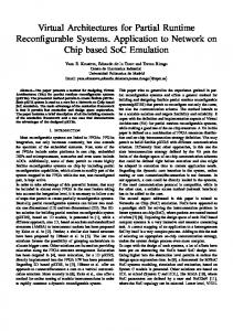
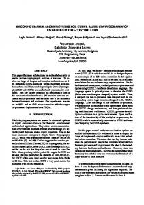
2 levels of complexity (till ten million Circuit description (VHDL, Schematic …) of gates in Xilinx VIRTEX II) and several levels of granularity (LUTs, Synthesize to logic blocks registers, multipliers, RAMs, processor core, etc.) Place logic blocks in FPGA Designers are then faced to the difficult choice of the target FPGA device that is critic since it can Route connections strongly affect the final system's performances. To help them in that FPGA programming file task, it is necessary to develop tools that compare FPGA's architectures. Figure 1. FPGA Design Flow [2] With such tools designers could improve adequacy between application and architecture and then choose the best one for their application. Today, a way to compare two architectures is to measure application's performances on different hardware targets. In that case the comparison is made at the end of the design flow, which is shown in figure 1. However, the time consuming place and route step is a major inconvenience when the designer needs to compare numerous devices. Moreover, making the comparison at the end of the design flow means to compare all the flow's steps (in particular the place and route algorithms) and not only the FPGA architecture's performances. Since, the steps of the design flow are very different between two manufacturers, the architecture's performances comparison is only possible between different devices of the same manufacturer which conduct to a limited design space exploration! A solution to the problem of architecture comparison, is to define a retargetable FPGA design environment. Figure 2 shows the differences between actual dedicated FPGA design environment (a) and the retargetable FPGA design environment that we propose (b). For dedicated environment, each architecture (expect for the same manufacturer's architectures) is linked to a specific design tool. For retargetable environment, a unique design tool is requested for all architectures. Hence, architectural comparison is possible since synthesis algorithms are common. However, such generic environment is possible only if a reconfigurable architecture modeling method is defined. This method must permit to describe efficiently the architectures to compare. In this paper we focus on that point which is a key aspect in the definition of the environment. We can notice that a similar wok has been carried out, at the Berkeley University, on a retargetable scheme for Digital Signal Processor (DSP) architecture selection [3]. In our approach, from an architecture instance (based on the modeling method presented in the paper), a performance estimation method is performed in order to compare different architectural solutions. The
3 modeling method aims to characterize a large panel of reconfigurable architectures. Its objective is to support the description of commercial FPGA's architectures but also no commercial FPGA's architectures emerging from research works. Thus, the proposed modeling method will support the evolution of future FPGA architectures. Application
Dedicated architectural model 1
Dedicated design tool 1
Architecture n°2
Application
Dedicated architectural model 2
Dedicated design tool 2
Architecture n°2
a) Dedicated FPGA design environments
Generic architectural model
Architecture n°1
Retargetable design tool
Architecture n°2
b) Retargetable FPGA design environment
Figure 2. FPGA design environment a) dedicated b) retargetable This paper is organized as follows, in section two we present a survey dealing with reconfigurable architectures and synthesis tools which are based on a reconfigurable architecture modeling. Section three, explains our reconfigurable architecture modeling method. Then, in section four, a Xilinx Virtex II device is modeled to illustrate our approach. Finally, section five gives us the opportunity to conclude and to propose some extensions to this work.
2.
SURVEY
2.1
Reconfigurable FPGA architectures
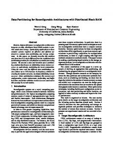
Current FPGAs are composed of configurable logic elements, which are connected through routing resources. Some FPGAs have also embedded RAM memories, processor core (such ARM 9 for Altera Excalibur device [4]), phase locked loops and inputs/outputs configurable blocks. As regards the logic blocks, they are usually build with LUTs and registers. Nevertheless, for some devices (like Xilinx Virtex device [5]), the logic blocks are build with coarse-grained operator like multiplier or adder. The different elements of a FPGA are arranged in several architectural forms. Two architectural styles are predominant; the island style (the greater part of the Xilinx's architectures) and the hierarchical style (the greater part of the Altera's architectures), figure 4 shows the island style architecture of a
4 Xilinx Virtex II device. These architectural styles have mainly an influence on the routing resources layout. Numerous research projects focus on new reconfigurable architectures definition. Such new architectures innovate the logic blocks size, form and granularity level. For example, the project carried out at the Twente University (The Netherlands) defines an original architecture called Field Programmable Function Array (FPFA), [6]. FPFA is composed of a matrix of processor tile, each processor tile contains multiple reconfigurable ALUs, local memories, control unit and communication unit.
2.2
FPGA architecture modeling
Among works dealing with reconfigurable architecture modeling, two are especially significant. Both correspond to place and route tools. Even if the study of place and route algorithms is not the issue of this paper, these tools are relevant to our work since they exploit a reconfigurable architecture modeling method in order to be technological independent. In this paper we only focus on the reconfigurable architecture modeling part of the tools. The first one is called Versatile Place and Route (VPR). It was developed by Vaughn Betz and Jonathan Rose at the Toronto University (Canada) [2]. The second one was developed by Loïc Lagadec and Bernard Pottier at the UBO1 University (France) [7, 8]. In the VPR tool, the modeling method is structural and is strongly oriented to island style architectures. A reconfigurable architecture is described in a structural way: number of LUTs in a CLB2, width of routing channels, connection styles, etc... This type of modeling allows to quickly modify a parameter of the architecture (i.e. the number of LUT inputs) in order to evaluate the impact on the device performances. However, this modeling type is tightly specialized for island style architectures with a fine level of granularity (LUTs, registers). Hence, its extension to a more complex architecture with other patterns of computation and connection is difficult. In the UBO tool, the modeling method is functional. Each element of the architecture is described by the function it is able to perform (for example, a four inputs LUT can execute a logical function with four inputs and one output). The functional modeling enables to describe a large panel of architectures (hierarchical or island style) and the description is technological independent. The designer can define new types of element since the functionality is known. This modeling is attractive, however it deals with a low-level granularity and each element is characterized by only 1 2
"University of Occidental Brittany", Brest, France. CLB is an acronym for Configurable Logic Block, it is a Xilinx's term.
5 one function. This is due to the Name VPR UBO's tool underlying place and route Structural Functional Modeling type algorithms. In case of complex Island style architecture composed of Yes Yes architecture memories, coarse-grained Hierarchical No Yes and/or multi-function operators architecture No-homogeneous these features can restrict the No Yes architecture modeling of the architecture. Yes Yes Routing modeling Main characteristics of both Partially Yes Logic blocks modeling reconfigurable architecture Embedded memories modeling are summarized in No No modeling table 1. If the designer wants to Arithmetical elements No No describe architecture composed modeling Input/output blocks of numerous distinct elements Yes No modeling in a technological independent way, the functional modeling Table 1. Main characteristics of both reconfigurable architecture modeling types approach is more adapted than the structural modeling. To conclude this survey, the following remarks can be done: the modeling must permit to describe functionally architecture and to represent hierarchical or island styles. Several levels of granularity, numerous types of elements and heterogeneous architectures must be considered. Finally, the modeling must be able to take into account the future architectural evolutions.
3.
MODELING PRESENTATION
In our approach, the architecture's elements are functionally described and the modeling allows to represent different architectural styles and different architecture's elements. However, the routing resources are not described since the aim of this modeling is to support a performance estimation tool and not a place and route tool. Nevertheless, the routing resources must be taken into account in the estimation tool as they have significant effects on device performances, they can have a power consumption upper than the half of the device power consumption [9] and they can slow down signals in the device [2]. Thus, connection resources are taken into account by connection costs in the proposed modeling. There are two types of element in the modeling; the hierarchical element and the functional element. The hierarchical element is used to describe the architecture's hierarchy. It can be composed of functional elements and other hierarchical elements. It is defined by five characteristics:
6 – its name, it is a label, – the number of such elements in the current hierarchy's level, – its reference, that is composed of two numbers, the first one for the current hierarchy's level (0 is the uppermost level), the second one for the number of that element in the current hierarchy's level, – the list of (hierarchical or functional) elements that are embedded in this hierarchical element, – the connection costs between embedded elements (routing resources consideration). The functional element is used to describe the architecture's resources. For classical FPGA architecture, it corresponds to logic element, input/output block, embedded memory and arithmetic element (i.e. adder or multiplier). But a functional element can describe various types of resources due to the functional approach. It is defined by seven characteristics: – its name, it is a label, as for a hierarchical element, – the number of such elements in the hierarchical container element, – its reference, that is composed of two numbers, the first one for the current hierarchy's level (0 is the uppermost level), the second one for the number of that element in the current hierarchy's level, – its maximum use, actually routing a FPGA becomes difficult when the architecture's elements are overused, so for example only 99% of them can be really used, – its utilization costs, they correspond to latency and power consumption, – the list of functions that this element can realize, – the function utilization rules, these rules are used to specify the possibility of parallelism or exclusiveness between functions. Figure 3 illustrates the FPGA name modeling, different levels : of hierarchy are Hierarchy's hierarchical level 1 represented. This feature functional name: name: is important to model number: number: reference: 1.2 hierarchical architecture reference: 1.1 connection costs: maximum use: % style. element 1: 2.1 use costs: element 2: 2.2 In this modeling, there function 1: f1 …. function 2: f2 are two types of costs, the function 3: f3 Hierarchy's functional hierarchical connection costs … level 2 name: name associated to the … : number: number: reference: 2.1 reference: 2.2 hierarchical elements and rule 1: (f1, f2) parallel rule 2: f3 only connection costs: maximum use: % the utilization costs …. use costs: element 1: 3.1 …… associated to the element 2: 3.2 …… …. functional elements. The utilization costs Hierarchy's level 3 correspond to delay and Figure 3. Modeling illustration
7 power consumption costs, which represent the latency and the power consumption of a functional element. The connection costs model the delay and the power consumption of routing resources between two elements in a same hierarchical element. These costs are requested to take into account the impact of routing during the estimation process. To efficiently estimate an application it is necessary to have information about the resources that can support the architecture and the related performances (speed, consumption). In our modeling method all these information (through the functional modeling and the modeling costs) are precisely defined which guaranty that the estimation process can be performed efficiently. The modeling cost can be defined with two approaches. If the designer wants to rapidly evaluate the performances of several architectures, he can define relative costs since, in that case, the aim is not to obtain accurate estimations but to identify the best architecture in term of relative performances. If the designer wants to compare precisely several architectures, the costs must be more precise to take into account the whole characteristics of each architecture. In that case, the designer can settle the different costs through delay and consumption measures. However this task can be very tedious in order to obtain precise characterisations. In our work, costs are defined relatively since we want to explore rapidly several architectures.
Figure 4. Virtex II architecture
8
4.
XILINX VIRTEX II MODELING
Several experiments on the following devices, Xilinx XC4000, Xilinx Virtex, Xilinx Virtex II and Altera Apex, have been carried out at the laboratory in order to validate the proposed modeling. In this section the results with a Xilinx Virtex II XC2V1000 (package FF896) device are presented. This device's architecture is illustrated in figure 4. FPGA: Virtex (package FF896)
II
XC2V1000
ELEMENT 0 Type: hierarchical Name: Virtex II XC2V1000 Number: 1 Reference: 0.1 Element1: 1.1 Element2: 1.2 Element3: 1.3 Element4: 1.4 Connection costs 1.1-1.1: 2ns 1.1-1.2: 2ns 1.1-1.3: 2ns 1.1-1.4: 2ns 1.2-1.2: 1ns 1.2-1.3: 1.5ns 1.2-1.4: 1.5ns 1.3-1.3: 1ns 1.3-1.4: 1ns 1.4-1.4: 1ns END ELEMENT 0 ELEMENT 1 Type: functional Name: IOB Number: 432 Reference: 1.1 Utilization max: 100% Latency: 10ns Power consumption: 2 mW +(0.4mW/1MHz)*f Function 1 (f1): input Function 2 (f2): output Function 3 (f3): input/output Rule 1: (f1, f2, f3) exclusive END ELEMENT 1 ELEMENT 2 Type: hierarchical Name: CLB Number: 1280 Reference: 1.2 Element1: 2.1 Connection costs 2.1-2.1: 0.2ns END ELEMENT 2 ELEMENT 3 Type: functional Name: SLICE Number: 4 Reference: 2.1
Maximum use: 98% Latency: 4ns Power consumption: 1 mW +(0.4mW/1MHz)*f Function 1 (f1): logic (1, 2, 3 or 4 inputs) whit asynchronous output Function 2 (f2): logic (1, 2, 3 or 4 inputs) with synchronous output Function 3 (f3): fast adder 1 bit with asynchronous output Function 4 (f4): fast adder 1 bit with synchronous output Function 5 (f5): fast adder 2 bit with asynchronous output Function 6 (f6): fast adder 2 bit with synchronous output Function 7 (f7): 16 bit shift register Function 8 (f8): ROM 16*1 bit Function 9 (f9): ROM 16*2 bit Function 10 (f10): ROM 32*1 bit Function 11 (f11): RAM 16*1 bit Function 12 (f12): RAM 16*2 bit Function 13 (f13): RAM 32*1 bit Rule 1: (f1, f2, f3, f4, f5, f6, f7, f8, f11) parallel two by two Rule 2: (f9, f10, f12, f13) exclusive END ELEMENT 4 ELEMENT 5 Type: functional Name: SelectRAM Number: 40 Reference: 1.3 Maximum use: 100% Latency: 15ns Power consumption: 1 mW +(0.4mW/1MHz)*f Function 1 (f1): Single-port RAM 16384*1 bit Function 2 (f2): Single-port RAM 8192*2 bit Function 3 (f3): Single-port RAM 4096*4 bit Function 4 (f4): Single-port RAM 2048*9 bit Function 5 (f5): Single-port RAM 1024*18 bit Function 6 (f6): Single-port RAM 512*36 bit Function 7 (f7): Dual -port RAM 16384*1 bit Function 8 (f8): Dual -port RAM 8192*2 bit
Function 9 (f9): Dual -port RAM 4096*4 bit Function 10 (f10): Dual -port RAM 2048*9 bit Function 11 (f11): Dual -port RAM 1024*18 bit Function 12 (f12): Dual-port RAM 512*36 bit Rule 1: (f1, f2, f3, f4, f5, f6) exclusive Rule 2: (f7, f8, f9, f10,f11,f12) parallel two by two END ELEMENT 5 ELEMENT 6 Type: functional Name: Multiplier Number: 40 Reference: 1.4 Maximum use: 100% Latency: 15ns Power consumption: 1 mW +(0.4mW/1MHz)*f Function 1 (f1): MUL 18*18 unsigned Function 2 (f2): MUL 17*17 unsigned Function 2 (f2): MUL 8*8 unsigned Function 4 (f4): MUL 7*7 unsigned Function 5 (f5): MUL 6*6 unsigned Function 6 (f6): MUL 5*5 unsigned Function 7 (f7): MUL 4*4 unsigned Function 8 (f8): MUL 8*8 signed Function 9 (f9): MUL 6*6 signed Function 10 (f10): MUL 5*5 signed Function 11 (f11): MUL 4*4 signed Function 12 (f12): MUL 3*3 signed Function 13 (f13): absolute value 2*18 bit Function 14 (f14): two's complementer 2*18 bit Function 15 (f15): two's complementer 2*9 bit Rule 1: (f1, f2, f3, f8, f13, f14, f15) exclusive Rule 2: (f9, f6) parallel Rule 3: (f10, f5) parallel Rule 4: (f6, f6) parallel Rule 5: (f11, f4) parallel Rule 6: (f11, f12) parallel END ELEMENT 6
Table 2. Virtex II XC2V1000 (package FF896) device model
The Virtex II has an island style architecture. Nevertheless, there are two hierarchy's levels for this architecture. At the upper hierarchy's level there are the Input Output Blocks (IOBs), the Configurable Logic Blocks (CLBs), the embedded RAM memories (SelectRAM) and the multiplier blocks. The
9 CLBs contain four logic slices. Each slice is realized with two four inputs LUTs, two registers and two fasts carry chains. Hence, in this architecture's model there are six elements; two hierarchical elements and four functional elements. The hierarchical elements are; the FPGA composed of hierarchical elements called CLB and three functional elements called IOB, Multiplier and SelectRAM, the CLB are composed of functional element called Slice. The Virtex II XC2V1000 (package FF896) model is shown in table 2. Each functional element is characterized by its utilization costs (latency and power consumption), its list of functions and its function utilization rules. The number of functions depends of the functional element, for example a Slice can realize nine exclusive functions and four two by two parallel functions. The modeling of the Virtex II presents the use of the modeling and its ability to describe complex architecture with several types of elements (memories, arithmetic elements, logic elements). Moreover, once a device in a family is modeled, it is very easy to generalize the model for all the device of that family since the architecture is the same, just the number of elements changes (like the number of logic blocks, the number of input/output blocks, or the number of memory bits, etc.).
5.
CONCLUSION
The definition of an open design environment for reconfigurable architectures imposes to define a reconfigurable architecture modeling method. This paper presents an original modeling method based on a functional approach. The proposed modeling allows to describe a large architecture range, including heterogeneity, hierarchy and multi-granularity levels. It results from the study of actual and emerging architectures as well as the study of reconfigurable architecture modeling methods. Table 3 summarized the main characteristics of the proposed method in comparison with the VPR and UBO approaches (Table 1). This modeling is natural and can easily evolve in order to take into account new features of future architectures.
10 The aim of our work is to propose a modeling, which could federate the reconfigurable domain researchers. The use of a common modeling will permit to fill up the important lake of reconfigurable architectures comparison tools. The interest of our approach is double: first with an open design environment the researchers will be able to compare their new architectures with others, and second the designers will be able to explore the design space in order to select the best architecture for their application. Our actual works focus on a performance retargetable estimation method for reconfigurable architectures which is based on the proposed modeling method. This estimation tool will constitute one of the tiles of the open design environment.
6. [1] [2] [3]
[4] [5] [6] [7] [8]
[9]
Name Modeling type Island style architecture Hierarchical architecture No-homogeneous architecture Routing modeling Routing impact modeling Logic blocks modeling Embedded memories modeling Arithmetical elements modeling Input/output blocks modeling
Proposed modeling Functional Yes Yes Yes No Yes Yes Yes Yes Yes
Table 3. Results with proposed modeling
REFERENCES Katherine Compton. Architectures For Run-Time Reconfigurable Systems. Master's Thesis, Dept of ECE, Northwestern University, Evaston, IL USA. December 1999. Vaughn Betz, Jonathan Rose and Alexander Marquardt. Architecture and CAD for Deep Submicron FPGAs. Klumer Academic Publishers, 1999. Naji Ghazal, Richard Newton, Jan M. Rabaey. Retargetable Estimation Scheme for DSP Architecture Selection. ASP-DAC 2000, Yokohama, Japan, Jan 2000, pp. 377380. Technical report, 2001. http://www.altera.com Product Specification, 2000. http://www.xilinx.com Paul M. Heysters, Japp Smit, Gerard J.M. Smit and Paul J.M. Havinga. Mapping of DSP Algorithms on Field Programmable Function Arrays. FPL'2000, August 2000. Loïc Lagadec. Abstraction, modélisation et outils de CAO pour les circuits intégrés reconfigurables. PhD Thesis, Université de Rennes1, 2000. Loïc Lagadec, Bernard Pottier. Object oriented meta-tools for reconfigurable architectures. In Conference on Reconfigurable Technology FPGAs and reconfigurable Processors for Computing and Application, 2000. Varghese George, Hui Zhang, Jan Rabaey. The Design of a Low Energy FPGA. In Proc. Int. Symp. On Low Power Electronics and Design (ISLPED'99), pages 188-193, 1999.