1, No. 1, January, 2008. 45. A Modular-based Miniature Mobile Robot for Pervasive Computing. Yan Meng, Kerry Johnson, Brian Simms, and Matthew Conforth.
International Journal of Hybrid Information Technology Vol. 1, No. 1, January, 2008
A Modular-based Miniature Mobile Robot for Pervasive Computing Yan Meng, Kerry Johnson, Brian Simms, and Matthew Conforth Stevens Institute of Technology, Hoboken, NJ 07030, USA {yan.meng, kjohnson, bsimms, mconfort}@stevens.edu Abstract Increasingly, innovations in miniaturization and embedded systems are making pervasive computing a reality. Meanwhile, similar advancements in robotics have made autonomous mobile robots easier to develop and more cost-efficient. However, since the field of ubiquitous robotics remains relatively unexplored, we develop SMARbot (Stevens Modular Autonomous Robot), as a tool to explore the pervasive capability of miniature robots. The SMARTBot was designed to be a highly modular, adaptable, inexpensive base model to integrate miniature mobile robots into the pervasive computing environment. The hardware and software architecture of the prototype are proposed. The experimental results demonstrate the feasibility and efficiency of the SMARbot in the real-world scenarios.
1. Introduction Pervasive (or ubiquitous) computing has long been hailed as the next age of computers [1]. It revolves around the concept that computers do not need to be recognized in order to aid humans in their daily work. In a ubiquitous environment, computers will “pervade” the user's world, using the semantic web or other advanced networks to harness a plethora of information and services. Advancements made in processing power, as well as the miniaturization of technologies, have made designs smaller, more complex, and more powerful than ever. Therefore, we are finding that the realm of ubiquitous computing offers great opportunity for advancement. Although it takes many different forms, pervasive computing commonly requires the cooperation of novel user interfaces, wireless communications, and computer processing power to assist humans in everyday tasks [1] [2]. Ubiquitous robotics is the study and implementation of robots as agents to assist humans within an environment of pervasive computing [2]. Although the technology for ubiquitous robotics is becoming increasingly available, the field remains relatively undeveloped. We present SMARbot (Stevens Modular Autonomous Robot) as a first step towards tackling this challenge. SMARbot is an inexpensive, modular robot that will be equipped with fundamental functionalities and an intuitive library for ease of programming. SMARbot has the following characteristics: • Reconfigurable hardware. SMARbot's hardware will be fully reconfigurable; i.e., it will adapt autonomously to environmental conditions at a very low level, allowing robust performance in diverse situations while avoiding the limitations of a pure software implementation. • Reconfigurable and reusable software. Since most of the software for a reconfigurable system is inherently reusable, it is efficient to reuse these software assets in the
45
International Journal of Hybrid Information Technology Vol. 1, No. 1, January, 2008
development of new applications. • Expandability and modularity. Existing hardware can be upgraded, and new hardware modules or software modules can be added to the system while the other parts maintain their functionality. • Low-cost and low-power. Power-efficient design will provide longer runtime for SMARbots with limited onboard battery power. Low-cost design will make it affordable to produce multiple robots which will improve system robustness and efficiency through the use of swarming algorithms. SMARbot is still in the prototype phase, but its current implementation illustrates proof of concept, and its modular design makes it possible for SMARbot to perform in various realworld applications. This paper is organized as follows: related work is discussed in Section 2. The architecture of the SMARbot is proposed in Section 3. Section 4 presents some experimental results and the ongoing prototype of the SMARbot. Finally, the conclusion and future work are discussed in Section 5.
2. Related work Ubiquitous computing consists of technologies which aid users in performing tasks without the knowledge of the computers’ presence. One example of a ubiquitous computing implementation is the PlantCare [3]. PlantCare deployed sensors in houseplants to monitor their conditions while robots can provide water, recharge, and calibrate the sensors. Scholtz and Consolvo [4] attempted to create a framework to ensure a consistent user experience over multiple systems. They created a series of measurements to help researchers determine the merit of a given pervasive computing application. A locating algorithm for ubiquitous computing systems was proposed in [5], which focused on GPS systems, and discussed how a smaller scale system with greater resolution could be constructed and marketed commercially. With the advances in wireless communication, embedded computing systems, and sensor technologies, more and more researchers have started developing ubiquitous robots for various applications. Kim and his colleagues have been developing a ubiquitous robot system, Ubibot, since 2000 [6]. This Ubibot system provides an intelligent connection between perception and action, where three components are included: Sobot (intelligent software robot), Embot (perceptive embedded robot), and Mobot (physically active mobile robot). Sukhatme and Matarić [7] provided a general overview of ubiquitous robots focusing on communication over the internet to allow the interaction between robots and remote users. Ahn et al. [8] described how middleware can be used to allow robots in a pervasive computing environment to use “plug and play” hardware. This is demonstrated by UPnP (Universal Plug and Play), which creates a personal area network that allows components to communicate without being connected by wires. Compared to the solutions which use a single mobile robot with multiple sensors in a ubiquitous environment, a multi-robot system can provide more robustness (the tasks can still be carried on despite failure of one or more robots) and efficiency (due to parallel processing). Abielmona et al. [9] focused on the software (and to a lesser degree hardware) methods to construct robots which act cooperatively through the use of wireless
46
International Journal of Hybrid Information Technology Vol. 1, No. 1, January, 2008
communication. Fox et al. [10] proposed a method for multiple robots to synchronize their information about a particular environment, allowing faster mapping of an unknown area. Inspired by social insects, Meng et al. [11] proposed a hybrid ACO/PSO (Ant Colony Optimization/Particle Swarm Optimization) coordination method for swarm robots, where two coordination processes among the robots are utilized. One process is a virtual stigmergy based algorithm to guide the agents’ movements, while the other process is Particle Swarm Optimization’s cognitive capabilities through local interaction, which aims to achieve the balance for each agent between exploration and exploitation. A collective site preparation using swarm robots has been discussed in [12], where a site preparation algorithm was developed based on the nest construction behavior of a particular species of ant, Leptothorax albipennis. All of above systems focus on the software intelligence, from the hardware point of view, reconfigurable and evolvable hardware can provide drastically decrease processing time of certain computations. The advanced development of FPGA (Field-Programmable Gate Array) allows dynamic reconfiguration of logic in real time, where genetic and evolvable algorithms can be applied to reconfigure the hardware. Stoica [13] proposed a synopsis of the field of evolvable hardware (EHW), where a feasible architecture was presented, and evolutionary mechanisms were used in hardware design and self-reconfiguration. Another example of using genetic algorithms in evolvable hardware was proposed in [14], where a genetic programming based method was presented for robot control, and the hardware reprogrammed itself to the “best fit” of its stochastically generated configurations. The case study of this method was two cooperative autonomous mobile robots, which use evolutionary programming to learn how to work together in moving an object around obstacles. To improve system robustness, Hereford and Pruitt [15] proposed a method for sensor failure detection and the adaptation of the FPGA with less sensors to optimize the operating conditions.
3. SMARbot architecture 3.1. Generic architecture of SMARbot The generic architecture of SMARbot is shown in Figure 1. The objective of this architecture is to provide a modular framework to systematically build a pervasive robot system. Generally, three layers are included: the user interface layer, the HW/SW configuration control layer, and the sensor/actuator layer. In the user interface layer, multiple tasks can be defined by users. A task is a high-level description of a function to be performed by SMARbot. For example, “move to point x.” When the post-conditions of one task and the pre-conditions of the next are satisfied, a dynamic reconfiguration can be performed within the system in the configuration control layer. Multiple control subsystems can execute in parallel and operate independently or cooperatively. A core utility subroutine library can be predefined for software reconfiguration implemented in the microprocessor, and a core component library can be predefined for hardware reconfiguration implemented in the FPGA. The FPGA reconfiguration can be triggered and controlled by the microprocessor. Configuration routines are created by combining modified reusable routines at the adjacent low-level or at the library level. The sensor/actuator layer consists of multiple sensors and actuators with corresponding device drivers and signal processing modules.
47
International Journal of Hybrid Information Technology Vol. 1, No. 1, January, 2008
Figure 1. A generic architecture of SMARbot Each control module may have one or more input ports, one or more output ports, and any number of resource connections. Input and output ports are used for communication between tasks in the same subsystem, while resource connections are used for external communication (e.g. to the other subsystems, or the user interface). In order to provide automatic integration of the control modules, it is necessary that the functionality of the module is implemented as a few basic components. All of the data flow, communication, synchronization, and scheduling should be handled automatically by the underlying operating system. Our model of a control module provides a generic structure that is applicable to both periodic and aperiodic realtime tasks. Our framework is designed especially to support reusable and reconfigurable hardware and software. The change in configuration can occur either statically or dynamically. In the static case, only the task modules required for a particular configuration are created. In the dynamic case, the union of all task modules required is created during initialization of the system. For a dynamic reconfiguration, the stability of the system becomes a concern. In such cases, when the dynamic reconfiguration begins, a global critical session flag will be turned on to indicate there are runtime reconfiguration is under progress. 3.2. Prototype of SMARbot SMARbot is approximately the size of a three inch cube, as shown in Figure 2, with a chassis constructed of folded aluminum sheet. The circuit boards are three inches square, and are attached to the chassis with standoffs. The wheels, which are constructed of acetal plastic with an o-ring tire, are driven by a pair of fifteen millimeter diameter Faulhaber gear motors with sixteen pulse per revolution encoders. The current version has the following components: infrared sensors, ZigBee module, microprocessor, motor driver, and power supply. IR sensors are used to detect the distance between the robot and obstacles or targets.
48
International Journal of Hybrid Information Technology Vol. 1, No. 1, January, 2008
The ZigBee module is used for wireless communication with other robots or a base station. The microprocessor is responsible for on-board computations. Motor drivers are utilized to control the robot wheels. The block diagram of the SMARbot hardware architecture is depicted in Figure 3. Currently, SMARbot is powered by a rechargeable 250mAh NiMH battery or adjustable power supply for testing purposes only. The power supply contains three synchronous buck converters and a linear regulator to provide the required voltages for the logic components. The AT91SAM7S256 ARM is used as the on-board microprocessor, and it is installed on an Olimex header board which allows for maximum flexibility in the prototyping stage since no soldering is required to make connections. A JTAG connector is also provided for easy programming of the chip. The chip itself contains UARTs, PWMs, and ADCs which are used for communication, motor control, and sensing. The processor runs a lightweight open source real-time operating system called FreeRTOS, which supports both preemptive and cooperative operation. The use of an RTOS allows for easy prioritization of tasks, scalability, and complexity.
Figure 2. (a) Top view of prototype assembly: (1) IR sensor, (2) ZigBee module, (3) Microcontroller, (4) motor driver, (5) power supply. (b) Side view of SMARbot with a CD for scale. Mounted on the chassis are four Sharp infrared range sensors that have a range of four to thirty centimeters, with a dead zone from zero to four centimeters. These IR sensors not only prevent the robot from colliding with objects, but they also allow for a limited capability of collecting map information. An essential part of being ubiquitous is being context-ware. This is realized in the current system through the infrared sensors, which allow SMARbot to detect the physical environment around it. The above attributes are amplified by the fact that SMARbot has a Zigbee wireless module as one of its core components, allowing it to communicate in a mesh networking fashion with other SMARbots and other networked systems controlled by a base station. Through wireless communication, information can be easily shared between robots, which leads to efficient context awareness for a large scale region. This is one of the major advantages of using multi-robot systems, where the effortless spread of knowledge through the swarm can provide special advantages in the pervasive realm.
49
International Journal of Hybrid Information Technology Vol. 1, No. 1, January, 2008
IR sensors
ZigBee
Camera
optional sensors
Sonars Bumper switches
Microprocessor
FPGA
optional sensors Motors
Optional RAM/FLASH
Figure 3. Hardware block diagram of SMARbot The major reason for us to choose Zigbee instead of 802.11 a/b/g as the communication protocol for SMARbot is that Zigbee consumes much less power that 802.11 a/b/g. The Xbee Zigbee module has approximately 15m indoor range, and draws about 50 milliamps at 3.3v. The module connects to the UARTs on the processor and is principally transparent. The mesh network allows for longer range since robots can pass information through each other. In order to connect to other networks such as 802.11a/b/g networks, the ZigBee module of SMARbot requires middleware. In addition, since pervasive computing is still in its early stages, it is unclear which protocols networks for pervasive computing (such as semantic web) will use in the future. Therefore the development of middleware to supply information to SMART may be unavoidable and extremely valuable. 3.3. Real-Time Operating System In a sophisticated embedded system, it is often necessary to utilize a real time operating system (RTOS) to schedule and coordinate the different processes that the system must execute. The project budget excluded most commercial RTOS options, but many open source solutions are available. RTLinux is extremely powerful; consequently it is rather demanding on the hardware. Also, such an extensive feature-set creates more complexity than this project requires. Given the low-level and invasive nature of some of our processes (e.g. resetting the FPGA during operation), it is advantageous to use an RTOS that allows more direct access to the hardware than is typical of RTLinux. After a survey of available open source RTOS implementations for the ARM7 architecture, we decided that FreeRTOS is the best compromise, providing the needed capabilities and devoid of features we will not use. One of the major advantages to the ARM architecture is the ability to use open source tools for everything from system software to development tools. As per [16][17], we have used the GNU tool chain compiler along with the Eclipse IDE [18], and OpenOCD [19] for JTAG onchip debugging.
4. Experimental results To evaluate the proposed prototype, some preliminary experiments have been conducted with the current prototype platform, which includes four infrared range sensors as well as ZigBee wireless communication.
50
International Journal of Hybrid Information Technology Vol. 1, No. 1, January, 2008
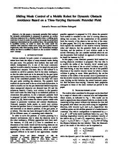
4.1. Autonomous obstacle avoidance Collision avoidance was implemented, as shown in Figure 4. The SMARbot uses infrared sensors to avoid an obstacle (i.e. a box) placed in its path. In the series of images below, the robot approaches the object, backs up to turn around, and moves forward past the object. There are two issues that were observed through the experiments. First, SMARbot sometimes has difficulty traveling in a straight line. This issue is not a concern at this time, as this was the expected result of open loop motor control. Once the closed-loop control is applied, this issue will be resolved. The only major issue found during experimentation was the lack of traction with the current wheel setup which appeared to have been caused by dust from the floor sticking to the rubber o-ring tires. SMARbot will have closed loop motor control with odometry allowing it to be capable of self-localization within the environment. However, this traction problem would cause major issues with odometry accuracy due to error accumulation. We intend to solve the problem by the addition of miniature tank style treads.
Figure 4. Autonomous Obstacle avoidance using a SMARbot 4.2. ZigBee wireless communication To test the wireless communication of SMARbot, a ZigBee module was interfaced to a PC using the Maxstream Xbee development kit. Then from a HperTerminal, commands are sent to SMARbot to control the motor speed and direction. Further, data collected by the infrared sensors was sent back to the HyperTerminal for inspection. This experimental setup proved to be useful in testing all hardware of the SMARTbot, where we noticed that the range of the ZigBee module was less than expected. The lack of range of MaxStream ZigBee module is not considered as a major issue here due to the potential use of mesh networking in the realworld systems. 4.3. Color blob tracking using a vision system Target detection and tracking using on-board camera systems is critical for SMARbot to work in a ubiquitous environment. Since the camera system has not been installed in the current version of SMARbot, some preliminary color blob tracking experiments were conducted offline with OpenCV to prepare for the final system integration. Preliminary results showed major issues with lighting sensitivity when thresholding RGB. Converting to HSV color space provided better performance, and only requires altering one variable to change the tracked color. Thresholding produces a binary image corresponding to pixels within a certain range of color from which the centroid of the tracked object can be determined. Figure 5 is a screenshot of the program used for prototyping the algorithm. On
51
International Journal of Hybrid Information Technology Vol. 1, No. 1, January, 2008
the left side is the original image from the camera, while on the right is the detected object. A small dot appears in the thresholded image representing the centroid of the tracked object. The goal of prototyping these algorithms is to ensure correct functionality before implementation in VHDL. Due to the volume of data that must be processed, we intend to implement most of the image processing in the FPGA to save processor resources. To this end, a device to convert RGB to HSV was designed in VHDL using Xilinx ISE and simulated with ModelSim. Since the RGB to HSV transform is a non-linear piecewise function, a behavorial model was written to decide how each variable should be applied to the equation. The signals are then fed into a structural model of the equation. Simulation and synthesis results showed correct operation and acceptable resource usage.
Figure 5. The blob tracking development program 4.4. Power consumption of the SMARbot SMARbot is supplied with power through a 7.4 volt two-cell lithium polymer battery. Table 1 lists the approximate power profile for the SMARbot prototype. Assuming a 10% loss due to voltage regulation, motor switching, and other factors, and considering a 7.4 volt battery, the total current draw for all components is approximately 200 milliamps. The battery on the SMARbot will be approximately 1500 milliamp-hours capacity, therefore yielding an approximate runtime of 7 hours. Table 1. Estimated Power Consumption Component Microcontroller ZigBee Infrared FPGA RAM Camera Encoders Motors Total
Current Draw (mA) 30 50 7* Various 45 25 12 80 n/a
Voltage 3.3 3.3 5 Various 3.3 5 5 7.4 n/a
Power (mW) 99 165 35 100 149 125 60 592 1325
Note: * 5% duty cycle is applied here.
4.5. Ongoing Prototype The current prototype is a major revision of the previous work based on knowledge gained from the creation of the initial proof of concept prototype. It addresses all aspects of the architecture we proposed in Figures 1, 2 and 3.
52
International Journal of Hybrid Information Technology Vol. 1, No. 1, January, 2008
The current prototype inherits the chassis, motor, and wheel assembly from the first revision. The circuit boards will be manufactured in such a way that they can be mounted to the chassis using standoffs. One of the first decisions made was to switch processors due to the lack of I/Os and an external memory bus on the AT91SAM7S256. The LPC2292 was chosen because, like the AT91SAM7S256, it has an ARM7TDMI core architecture. This means the existing software development environment can be left mostly unchanged due to the common architecture. This processor is generally well supported because of its widespread usage. This LPC2292 processor board has been designed, fabricated, and populated. It contains the LPC2292, 1 MB of SRAM, 16 MB of Flash ROM, and the 1.8V core voltage power supply. Since there were no major issues throughout this process, it meets the ease of fabrication design goal. If flux is properly applied during assembly, drag soldering methods can be used to quickly mount the fine pitch components (such as the processor, memory, and board-to-board interconnects) on the board without difficulty. The boards stack as expected, leaving clearance for taller components and also fitting on the chassis as predicted. One function that is omitted from the processor board is a JTAG port to program the processor. This has been moved to a debugging board, which also includes connection points for the GPIO. The board has been fully designed and is ready to be manufactured. The power board has also been designed and now contains only a 3.3 and 5 volt supply, plus battery supervisor circuitry and motor drivers. The previous power board prototype had 1.2, and 2.5 volt supplies as well, but these have been moved off the board since they are specific to the FPGA board. For the sensor/interconnect board design, various sensors must be chosen. The most likely options are infrared sensors, sonar sensors, bumper switches, and a camera. The camera will be interfaced with the FPGA board which can perform image processing tasks. It is important to note that due to the modular nature of the robot architecture, this can be changed or supplemented at any time. The tank style treads will also be considered for the chassis design in order to increase traction and improve odometry accuracy. The new chassis will also make room for a larger two-cell lithium battery pack.
5. Conclusion and future work A generic modular embedded system architecture for miniature mobile robots was presented in this paper, which provides a large amount of functionality in a small, low-power, low-cost, and highly modular platform. With a completely modular architecture that allows individual components to easily be added, replaced, or modified and a large number of sensor and actuator interfaces, many different miniature mobile robot systems can be constructed. Once the hardware design is finalized and fabricated, we will mainly focus on developing the software on the miniature robot systems. Algorithms for sensor data acquisition and motor control will be developed first. This will be followed by some higher level tasks, such as sensor perception, robot localization, and navigation techniques. To make the platform user friendly, most basic functions will be provided as libraries to the end users, who will only concentrate on high-level task-specific development.
53
International Journal of Hybrid Information Technology Vol. 1, No. 1, January, 2008
6. References [1] M. Weiser and J. S. Brown. “Designing Calm Technology”, Power Grid Journal, v. 1.01, July 1996. [2] Y. G. Ha, J. C. Sohn and Y. J. Cho, “Service-Oriented Integration of Networked Robots with Ubiquitous Sensors and Devices Using the Semantic Web Services Technology”, 2005 IEEE/RSJ International Conference on Intelligent Robots and Systems, 2005. [3] A. LaMarca, D. Koizumi, M. Lease, S. Sigurdsson, G. Borriello, W. Burnette, K. Sikorski, and D. Fox, “PlantCare: an investigation in practical ubiquitous systems”, Lecture Notes in Computer Science, Vol. 2498/2002, pp. 63-94. [4] J. Scholtz and S. Consolvo, “Towards a Discipline for Evaluating Ubiquitous Computing Applications”, Intel Research, January 2004, Available:http://www.intelresearch.net/Publications/Seattle/022520041200_232.pdf, [Accessed: June 4th, 2006]. [5] J. Hightower and G. Borriello, “Location systems for ubiquitous computing”, Computer, August 2001, pp. 57-66. [6] J. Kim, K. Lee, Y. Kim, N. Kuppuswamy, and J. Jo, “Ubiquitous Robot: A New Paradigm for Integrated Services”, IEEE International Conference on Robotics and Automation, Rome, Italy, 2007, pp. 28532858. [7] G. S. Sukhatme and M. J. Matarić, “Embedding Robots into the Internet”, Communications of the ACM, May 2000, pp. 67-73 [8] S. C. Ahn, J.-W. Lee, K.-W. Lim, H. Ko, Y.-M. Kwon, and H.-G. Kim, “Requirements to UPnP for Robot Middleware”, International Conference on Intelligent Robots and Systems, 2006, pp. 363-368. [9] R. Abielmona, E. Petriu, V. Groza, and T. Whalen, “Can an Intelligent Society of Robots Survive in a Hostile Environment?”, Canadian Conference on Electrical and Computer Engineering, 2003, pp. 12351238. [10] D. Fox, W. Burgard, H. Kruppa, and S. Thrun, “A probabilistic approach to collaborative multi-robot localization”, Autonomous Robots, June 2000, pp. 325-344. [11] Y. Meng, O. Kazeem, and J. Muller, “A Hybrid ACO/PSO Control Algorithm for Distributed Swarm Robots”, 2007 IEEE Swarm Intelligence Symposium, April 1-5, 2007, Honolulu, Hawaii, USA. [12] C.A.C. Parker and H. Zhang, “Collective Robotic Site Preparation”, Adaptive Behavior. Vol.14, No. 1, 2006, pp. 5-19. [13] A. Stoica, “Evolvable Hardware: From On-chip Circuit Synthesis to Evolvable Space Systems”, Proceedings of the 30th IEEE International Symposium on Multiple-Valued Logic, 2000. [14] D.W. Lee, C.B. Ban, H. S. Seok, K. J. Lee, K.B.Sim, and B.T. Zhang, “Behavior Evolution of Autonomous Mobile Robot Using Genetic Programming Based on Evolvable Hardware”, Proceedings of the IEEE International Conference on Systems, Man, and Cybernetics, 2000. [15] J. Hereford and C. Pruitt, “Robust Sensor Systems using Evolvable Hardware”, Proceedings of the 2004 NASA/DoD Conference on Evolvable Hardware, 2004. [16] J. Lynch, “ARM Cross Development with Eclipse Version 3,” Dec, 2005. [17] R. Barry, “Tutorial: Using a completely open source tool chain for ARM software development,” http://www.elektronikpraxis.vogel.de/fileserver/vogelonline/files/419.pdf. 2007. [18] The Eclipse Software Foundation, http://www.eclipse.org/. 2007. [19] http://openocd.berlios.de/web/, 2007.
54
International Journal of Hybrid Information Technology Vol. 1, No. 1, January, 2008
Authors Yan Meng is an assistant professor in the Department of Electrical and Computer Engineering at Stevens Institute of Technology, Hoboken, NJ, USA. She received her B.E. and M.E. in electrical engineering from Xian Jiaotong University, Xian, P.R.China, in 1991 and 1994, respectively. She received her Ph.D. in electrical engineering from Florida Atlantic University in December 2000. Her current research interests include real-time embedded systems, swarm intelligence, artificial intelligence, machine learning, swarm robots, multi-agent systems, and robot vision. Kerry Johnson received a B.E. degree in electrical engineering from Stevens Institute of Technology, Hoboken, NJ in 2006. He is currently pursuing a M.E. degree in electrical engineering at Stevens Institute of Technology, with a concentration in embedded systems. His research interests include robotics, embedded systems, and digital design.
Brain Simms is an undergraduate student at Stevens Institute of Technology currently working toward his B.E. in computer engineering, expected in 2008. While at Stevens, Brain has become interested in many topics, including robotics, machine learning, and real-time embedded systems.
Matthew Conforth received his B.E. in Computer Engineering in May, 2007 from Stevens Institute of Technology, Hoboken, NJ 2007, where he is currently a graduate student and research assistant. His research interests include artificial intelligence, human-robot interaction, mobile robots, swarm intelligence, and swarm robot systems.
55
International Journal of Hybrid Information Technology Vol. 1, No. 1, January, 2008
56