Development of a Multi-Arm Mobile Robot for Nuclear Decommissioning Tasks Mohamed J. Bakari, Khaled M. Zied and Derek W. Seward Engineering Department, Lancaster University, UK
[email protected],
[email protected] and
[email protected]
Abstract: This paper concerns the design of a two-arm mobile delivery platform for application within nuclear decommissioning tasks. The adoption of the human arm as a model of manoeuvrability, scale and dexterity is the starting point for operation of two seven-function arms within the context of nuclear decommissioning tasks, the selection of hardware and its integration, and the development of suitable control methods. The forward and inverse kinematics for the manipulators are derived and the proposed software architecture identified to control the movements of the arm joints and the performance of selected decommissioning tasks. We discuss the adoption of a BROKK demolition machine as a mobile platform and the integration with its hydraulic system to operate the two seven-function manipulators separately. The paper examines the modelling and development of a real-time control method using Proportional-Integral-Derivative (PID) and Proportional-Integral-Plus (PIP) control algorithms in the host computer with National Instruments functions and tools to control the manipulators and obtain feedback through wireless communication. Finally we consider the application of a third party device, such as a personal mobile phone, and its interface with LabVIEW software in order to operate the robot arms remotely. Keywords: Robotics, Nuclear Decommissioning, Hardware Integration, Kinematics, Control.
1. Introduction The UK government and the Nuclear Decommissioning Authority (NDA) are currently involved in the decontamination and decommissioning (D&D) of a high number of ageing nuclear power stations and other facilities. These nuclear plants often contain radioactive and other hazardous materials that are harmful to humans. Much of the decommissioning process utilises well established demolition techniques although there are complications within this process due to the risk of exposure of workers and the wider environment to radiation. Nearly all D&D activities that are too hazardous for direct human contact are presently executed using robotics systems however; many of these robotic systems are custom-designed for specific projects and are deployed by a crane rather than a remote vehicle. These systems are often expensive, unreliable, limited, and expose workers to unnecessary risks (IAEA, 2001). The NDA is looking for new and innovative technologies that will allow D&D operations in the UK to be faster, safer, more cost-effective and reduce the radioactivity dose levels to which workers are exposed. The application of a multi-arm robot system within D&D tasks has the potential to meet these requirements. This paper discusses the development, integration and control of a two-arm mobile robot system for application within the rapidly expanding field of nuclear decommissioning. A multi-arm robot system has the ability to perform two distinct operations simultaneously
International Journal of Advanced Robotic Systems, Vol. 4, No. 4 (2007) ISSN 1729-8806, pp. 387-406
or separately, it also has the ability to perform the same processing operation in a coordinated manner, or share a task such as holding and cutting a pipe. In this way multi-arm robots have many advantages over single-arm robots as has been noted by researchers and decommissioning agencies around the world (Alford, C. O. & Belyeu, S. M., 1984; Cox, J. D., et al 1995; Miyabe, T., et al 2004). There is demand for multi-arm robot systems within decommissioning, subsea and in space because of the potential presented their application for complex tasks compared to a ‘handicapped’ robot system (Cox, J. D., et al 1995). The research discussed in this paper has focused on the adoption of human arm manoeuvrability and dexterity as the starting point for operating two seven-function arms. This is applied in order to perform the co-operative and complex manipulation tasks found within D&D tasks and to facilitate movement within restricted spaces. The selected mobile platform is the BROKK 40 decommissioning robot, which is the smallest of the BROKK family. This machine consists of a moving vehicle with a single five degree of freedom manipulator, hydraulic tank, controller and remote-control device. It can be manoeuvred through small and confined spaces. The multi-arm system attached to the BROKK 40 is the Hydro-Lek HLK-7W with continuous jaw rotation mechanism. This consists of two seven-function manipulators (six rotary joints with a gripper). A system of wireless communication has been developed to control the manipulators and obtain feedback.
387
International Journal of Advanced Robotics Systems, Vol 4, No 4 (2007)
administration. It must be said, however, that many decommissioning contractors have experienced significant problems with complex customised robotic systems and hence remain sceptical about their deployment. Whereas conventional industrial robots now have a mean-time-between-failures (mtbf) of 70,000 hours, a typical customised one-off solution has an mtbf of only 5-6 hours. The majority of current automated systems employ virtually no autonomy or even programmed motion. Invariably there is a human in the control loop, and this is expected to continue for many years to come. This means that nearly all systems employ remote control, teleoperation or master/slave manipulation. Systems generally fall into one of four categories: 1. 2. 3. 4.
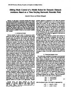
Fig. 1. Multi-Arm Mobile robot platform Both Proportional-Integral-Derivative (PID) and Proportional-Integral-Plus (PIP) control algorithms have been developed in the host computer with National Instruments tools and functions. The interfacing of a third party device, such as a personal mobile phone with LabVIEW software is currently being examined in order to control the arms. The Multi-Arm Mobile Robot System was developed following the refined design and system development process for nuclear decommissioning application, as discussed and illustrated in Section 2. This development process has already been applied to the development of Starlifter construction robot (Zied, K. 2004). It can also be adapted and applied to other research fields including space robot applications and subsea. The primary use of robotics in decommissioning applications is to reduce the radioactive dose levels to which workers are exposed during the decommissioning processes. There are many situations where, owing to the degree of radiation and the very long half-lives of the radioactive materials involved, robotics is the only feasible option. The Nuclear Regulatory Commission’s regulation 10 CFR 20 states that an occupational worker cannot receive more than 50 mSv per year for full body dose (U.S. Nuclear Regulatory Commission, 2004); once this dose has been reached the worker has to stop working immediately. This necessitates an increased number of workers to be employed in order to accomplish the necessary task. By using robots the number or workers is minimised, this in turn creates many additional savings including a reduction in the quantity of protective clothing needed and decreased
388
Relatively expensive customised solutions to specific problems. General purpose plant. Systems fabricated from off-the-shelf components. Automated process plant for packaging and waste processing.
This paper describes the development of a category 3, Multi-Arm Robot System for Nuclear Decommissioning (MARS-ND) device as illustrated in Figure 1. 2. The Development Process A robotic system generally comprises many modules that need to work together to perform a task. The required capability range of robots for hazardous environment is very wide depending upon factors such as the nature of the task, the degree of structure in the environment and the level of hazards. The development of advanced technology requires both a study of economic feasibility and an assessment of available technology. The identification of the required capabilities that a robotic system should have is not an easy task and it requires the use of a systematic approach that enables the developer to gather concrete information to help in satisfying the end user requirements. The adoption of a systematic approach in the development of any system requires the use of an appropriate development model, which takes into consideration the unique nature of the particular tasks. The many modules of a robotic system for decommissioning make it a multidisciplinary system in which the selection of a development model based on only one module is not appropriate (Zied, K. 2004). Seward, D. (1999) identified an important aspect of the development process, which is the difference between the development of a system for research purpose and a system for commercial purpose. The latter has welldefined end results, which allow the formulation of specific requirements, but the former is open-ended which means that it is difficult to identify specific requirements. Therefore, it is necessary to identify a starting point and an ending point for the research
Mohamed J. Bakari, Khaled M. Zied and Derek W. Seward / Development of a Multi-Arm Mobile Robot for Nuclear Decommissionig Tasks
project. The use of systems engineering principles allow for a research project to identify the user and the system requirements in a general manner and create architectures for the future research. This will allow different teams to collaborate even in different time periods. The adoption of a development model such as the Systems Engineering (SE) Model (Stevens, R., et al 1998) allows for the implementation of a partially developed system and supports the continuity of the research project. In a commercial project, the same principles can be applied but, as mentioned above, it is necessary to define the endpoint of the project. Stevens presented in detail the development process using the SE principles. All of the models presented are based on the basic sequential model. The sequential model steps are adopted to tailor a development model that suits the development of construction robotic systems. 2.1. Implementation of a partially developed system in a new system The SE process is designed to cope with complex systems; part of this complexity can come from the use of partially developed systems. It is necessary to emphasise the difference between legacy systems and partially developed systems. Legacy systems, as identified by Stevens, have been developed often without good documentation and are already in use as final products. Partially developed systems are systems whose development has been stopped for unknown reasons. The partially developed system can be documented and reengineered for further development in terms of the systems engineering principles. Figure 2 shows the implementation of a partially developed system in different stages of the development process. It is necessary to perform a complete analysis of the partially development system and identify the system functions, system architecture, and the system components. The output from this analysis is a document that describes the system objectives and component functionality. It is possible to recall the format of the architectural design document herein as a model for the output from the partially developed system analysis in terms of: 1. Component behaviour 2. Component functionality 3. Component interfaces 4. Component layout 5. Dependency & required resources 6. Test criteria The partially developed system document can then be fed into the system engineering process. Already developed components can be modified or integrated with the system according to the requirements of the architectural and the detailed designs. When this process is complete, the development process returns to the normal steps for integration and verification up to the final operation step (Zied, K. 2004).
Fig. 2. The use of a partially developed system in the development of a system using systems engineering principles 2.2. Elements of the development process It is assumed that the target task is to cut and remove pipes from inside a contaminated area in a nuclear power plant. The management decision is to adopt robotic technology capable of performing these tasks in such an environment, presuming that the economic study showed that this solution is feasible for the decommissioning tasks (Zied, K., et al, 2000). The main steps of the development model discussed above are as follows: 2.2.1 User requirements The user requirements capture process can be employed to produce the User Requirement Document (URD). The environment variables discussed by Bahr, N. (1997) can be represented pictorially to identify the working environment and all adjacent subsystems involved in the traditional methods and robotic solution. This is helpful in defining the user requirements and the system requirements for the new system (See Figures 3a and 3b). The client (the contractor who wishes to introduce the new technology) raises the following six issues: 1. The site is highly contaminated and requires the avoidance of direct human intervention 2. Pipe cutting should be as quick as possible with reasonable accuracy using existing saws and other supporting equipment 3. The system should be easily decontaminated following completion of the task
389
International Journal of Advanced Robotics Systems, Vol 4, No 4 (2007)
4. 5.
6.
The cost of the new system should be within the agreed limit A user interface should be provided together with information concerning operation and safety A compatible off-line system for task simulation, planning, scheduling, costing and report generation is required
The site and safety engineers raise the following issues: 1. The means of access to the working area should be identified prior to the actual operation 2. The supporting equipment, such as power sources, should be identified 3. A waste packaging and disposal route should be identified 4. The hazards involved in the system should be identified and a risk assessment should be prepared prior to implementation. 5. Surveillance cameras are needed for operation and site supervision
The main functions of the off-line system are: a. Receiving the contract information b. Creating simulations for the system components and the working site c. Identifying tasks d. Planning tasks e. Preparing task schedules f. Evaluating the contract costs g. Generating a descriptive report for the whole contract including prices h. Reviewing the resources required i. Reviewing safety issues, codes of practice and regulations j. Arranging for tools and logistics dispatch k. Issuing working orders The on-board system function is divided into six functions; these functions collaborate to perform the overall function. There are interdependencies between the systems involved in undertaking these separate functions. These functions can be decomposed as follows: 1.
(a) 2.
3.
(b) Fig. 3. Environmental variable: (a) Traditional method and (b) Robotic solution (adapted from Bahr, N. 1997) 2.2.2 System requirements It is now possible to identify the required system capabilities to meet the user requirements. The user requirements can be translated into system requirements which can be defined in terms of different functions. The main system is divided into two subsystems, the first is the off-line system, and the second is the on-board system.
390
4.
Handling input and output from and within the system a. Receiving work instruction and task details from the off-line system b. Sending and receiving information from and to different components of the system c. Monitoring the performance of the individual system components and assuring harmony d. Task monitoring and task sequence control Handling platform position a. Selecting the platform b. Moving the platform to a desired position c. Providing a stable position for the platform d. Interacting with other functions Handling environment information a. Monitoring the working area b. Checking for collisions in the working area c. Perceiving relative position and orientations w. r. t the working area d. Issuing safety warnings e. Interacting with other functions Handling motion a. Receiving position information b. Sending signals for position modification c. Rectifying position d. Path planning e. Interacting with other functions
Mohamed J. Bakari, Khaled M. Zied and Derek W. Seward / Development of a Multi-Arm Mobile Robot for Nuclear Decommissionig Tasks
5.
6.
Handle end-effector position a. Receiving commands b. Handling tools c. Providing a stable platform for tools d. Providing resources for other functions e. Providing desired configurations f. Interacting with other functions Handling tools a. Providing multiple tool docks b. Providing a stable platform for tools c. Providing easy engagement and disengagements of tools d. Sending tool status
2.2.3 Architectural design The architectural design concepts can be represented in three forms, all of which give increased understanding of the system under development. The first form is the system structure which defines the major component organisation and decomposition. The second form is the system behaviour which defines the inherent dynamics in the system and shows how the system will behave during operation and the system layout. Finally the system layout defines the physical interrelationship between the system components and their relative positions.
Fig. 4. MARS-ND structure
2.2.3.1 System structure For a robotic system it is possible to define the major components based on the functional decomposition presented in the system requirements. It is however difficult to make a relative structural decomposition or a hierarchy of the major components because all of them are distinctive and cannot be subsystems of each other. The decomposition of each component can be identified based on the sub-functions involved in the main function of the component. Figure 4 shows the major components of a robotic system structure which include: off-line simulation module, the user interface, the controller module, the sensing module and the manipulator & endeffector module. 2.2.3.2 System behaviour The system behaviour model shown in Figure 5 illustrates the top-level behaviour of the major components of the system. Clearer system behaviours may be illustrated by lower level subsystems, for example, communication behaviour in the controller module, where data is exchanged within the subsystem itself as well as between other subsystems in the architecture. Figure 6 shows an example of the controller module structure and hierarchy. Figure 7 shows a behavioural model of the controller module. Figure 6 consists of two main components: the high level controller and the low level controller. The high-level controller is concerned with kinematics and sensory data fusion; the low level controller is concerned with servocontrol of individual robot joints.
Fig. 5. System top level behavioural model
391
International Journal of Advanced Robotics Systems, Vol 4, No 4 (2007)
Fig. 6. Controller module structure
Fig. 9. The basic BROKK 40 mobile platform
Fig. 7. System controller behavioural model
2.2.3.3 System layout The top layout of the system is a direct interpretation of the physical component arrangement. The components perform the main functions illustrated in the functional decomposition diagram while their behaviour is illustrated in the behavioural model. The on-board system layout (See Figure 8) shows details of the final working system. The major components shown in Figure 8 are the six modules already identified in the behavioural module but with an emphasis on the components used in the design.
Fig. 10. Mounting bracket for twin manipulator arms
Fig. 8. MARS-ND layout
Fig. 11. Twin Hydro-Lek manipulator arms
392
Mohamed J. Bakari, Khaled M. Zied and Derek W. Seward / Development of a Multi-Arm Mobile Robot for Nuclear Decommissionig Tasks
2.3. The selected technologies and design issues for the on-board system The following points identify the core technologies for the major modules and indicate how they contribute to the satisfaction of the main system functions:
2.3.1 Mobility module Brokk 40 as shown in Figure 9 is an off-the-shelf machine and is the smallest demolition robot in the BROKK family. This machine is able to pass through 60cm wide doorways and is the appropriate machine wherever narrow openings have to be considered. The low weight of the BROKK 40 enables it to be used in most normal buildings and its small dimensions (Height: 940mm and Width: 600mm) allow it to operate in very confined spaces. The BROKK 40 consists of a moving vehicle with a five degree of freedom manipulator, five linear actuators, hydraulic tank, controller and remote control device. A universal bracket has been fitted at the end of the BROKK manipulator where the multi-arm system is attached (see Figures 10 and 11).
2.3.2 Manipulator platform module The selection of a manipulator of six degrees of freedom is essential to perform full motion in 3-D space. From the experience of previous working systems (Esposito, C., et al, 1993) the desirable characteristics of manipulators for working in hazardous environments can be identified as: 1. 2. 3. 4. 5. 6. 7. 8.
Rugged construction Waterproof Modular design Easy decontamination Rugged electronics Remote data communication system Pay-load carrying capacity over 200 kg On-board power supply
The specific user requirements introduce two important constraints which contribute to the technology selection process. Firstly the system should provide a stable platform for the tools. Locking facilities such as nonreturn valves or self-locking actuators can be used to lock the manipulator joints at any position and orientation even when the robot is de-powered. Secondly the requirement to use existing tools implies that the design of the endeffector should consider the tool manifold interfaces. Standard tool interfaces can be installed in the endeffector or in the tool changer docks. 2.3.2.1 Hydro-Lek HLK-7W Manipulator The HLK-7W manipulator is a rugged seven-function arm with a continuous jaw rotate mechanism and the gripper is dual function designed to grip an object and also cut ropes up to 19mm diameter (see Figure 12).
Fig. 12. 3D CAD model of Hydro-Lek HLK-7W arm Dimension: Length of arm Length of slew plate Height (stowed) Width
1500mm 410mm 800mm 180mm
Weight: Weight in air Weight in water
45kg 32Kg
Capacities: Wrist rotate 360° continuous Torque at 140 bar (across ports) 38Nm Lift capacity at full reach at 160 bar 150Kg Max working pressure 210 bars The azimuth yaw, shoulder pitch, elbow pitch, forearm roll and wrist pitch joints are fitted with feedback potentiometer sensors. These provide capability for manipulator positioning feedback better than 1 minute/degree without an initialisation requirement. There is a pressure sensor fitted to the dual function gripper/cutter. 2.3.3. Hydraulic system integration The BROKK 40 machine hydraulic system has enough power to drive Hydro-Lek arms either separately or together.
Fig. 13. Hydraulic integration
393
International Journal of Advanced Robotics Systems, Vol 4, No 4 (2007)
The hydraulic valve packs are installed onto one of the BROKK arm links close to the hydraulic integration point. Figure 13 shows the valve packs for the Hydro-Lek arms and the hydraulic hoses that connect between the valve packs and the BROKK hydraulic system.
2.
3. 2.4 Controller module The controller module consists of two parts, the highlevel controller, which is basically software based, and the low-level controller, which is a combination of software and hardware. The low-level controller consists of analogue to digital converters; digital to analogue converters and communication ports such as serial ports are PC based hardware. The controller is designed to control one or several joints at a time. Instructions for resolved motion and path planning will be sent from the high-level controller in the form of joint positions. A standard PID controller can be used in the design but the model of the joints should be identified first. As an alternative for the controller design, a data-based modelling technique, PIP, utilising true digital controller can be used to model the manipulator. Details of the control system are discussed in section 3. 2.5 Sensing module A robotic system’s intelligent capability can be measured in terms of how far its sensors are integrated into the system. The most important factor that needs to be considered when selecting a sensor is reliability. As described in the functional decomposition diagram, sensors are used for monitoring, guiding and positioning of the end-effector. For monitoring purposes, cameras can be used to provide clear images of the working area. Laser devices can be used in mapping the task area to create three-dimensional images of the workspace (Seward, D., et al, 2002). 2.6 User interface This module is the direct interface between the whole robotic platform and the operator. All the components involved in this module are software based and the design of this module requires the existence of the other modules, which are involved in the system operation. Graphical programming can help in rapid development of the required software components for the system as explained by (Zied 2004). 3. System controller design 3.1. Kinematics controller The kinematics controller is a software-based module. The behavioural model shown in Figure 14 shows the interrelationship between the module components. The behavioural model allows the division of the kinematics controller into five components: 1. Interfaces - represents interfaces of the input devices such as joysticks, spaceball, mobile
394
4.
5.
phone and other interfaces such as the simulated robot and sensors. Demand - deals with the demanded values of variables and rate in joints space and Cartesian space Processing - deals with processing the input variable and rates for conversion into interchangeable forms. It also deals with trajectories generation in joints space and Cartesian space. Other functions include singularities detection and issuing warnings for exceeding limits or ranges. Output and warnings - values for the joints variables, Cartesian variables and rates are monitored and warnings are visualised it mainly deals with the outputs to the user. Implementation - deals with the low-level controller interface in which data in the form of demanded joints variables and rate are passed to the low-level controller and the current joints variable fed-back to the user interface.
The user interface works as a shell containing all these sub-modules. The user interface controls inputs and monitoring outputs from the kinematics controller. 3.1.1. HLK-7W Arm Kinematics Robot manipulators can be considered as a set of bodies or links connected in a kinematic chain by joints (Lewis, F. L., et al 2004). The HLK-7W robot arm is a sevenfunction robot manipulator (six rotary joints and one prismatic joint for the gripper). Figure 15 shows the seven-function or seven degree of freedom HLK-7W manipulator. Joint one (azimuth yaw) rotates with axis perpendicular to plane XY. Joint two (shoulder pitch) rotates perpendicular to joint one. Joint three (elbow pitch) rotates parallel to joint two and is offset by link indicates as A. Joint four (forearm roll) is perpendicular to joint three and is offset by the link indicated as B. Joint five (wrist pitch) is perpendicular to joint four, parallel to joint three and is offset by the link indicated as C. Joint six (jaw) is perpendicular to joint five and is offset by the link indicated as D. The Hydro-Lek HLK-7W manipulator structure is kinematically defined by giving each link four parameters which are di, ai, Όi and ΅i. The four given parameters shown in Table 1 describe how to get from one joint to another. Neighboring links have a common joint axis between them. The distance along the common axis from one link to the next link is offset di. The amount of rotation about the common axis between one link and its neighbor is joint angle Όi. The definition of mechanisms by means of these four parameters is a convention called Denavit-Hartenberg (DH) (Cox, D., 2004; Denavit, J., & Hartenberg, R., 1955; Hemami, A., 1986). The location and orientation of each joint frame is shown in Figure 16.
Mohamed J. Bakari, Khaled M. Zied and Derek W. Seward / Development of a Multi-Arm Mobile Robot for Nuclear Decommissionig Tasks
No.
Twist Angle 0
Link Length
Joint offset
Joint Angle
0 0
0 0 Table 1. Hydro-Lek arm D-H parameters The constant D-H parameters for the Hydro-Lek arm, as shown in Table 1, are twist angle ΅i-1, link lengths ai-1, link offsets di and variable joint angles Όi.
Fig. 14. Behavioural Model for the Kinematics Controller
3.1.2. D-H Convention The D-H convention is a notation system developed to assign orthonormal coordinate frames to a pair of adjacent links in an open kinematic chain (Denavit, J., & Hartenberg, R., 1955). The procedure involves finding the link coordinates and using them to find 4×4 homogeneous transformation matrices composed of four separate submatricies to perform transformations from one coordinate frame to its adjacent coordinate frame.
3.1.3. D-H parameters Figure 16 shows the following connections: link i connected to link i-1 to link i+1 through ai. This figure is used to demonstrate the steps involved in determining the D-H parameters. This method involves determining four parameters to build a complete homogeneous transformation matrix. These parameters are the twist angle ΅i, link length ai, link offset di, and joint angle Όi. Parameters ΅i and ai are based on the geometry of the manipulator and are constant values based on the manipulator geometry, while parameters di and Όi can be variable (depending on whether the joint is prismatic or revolute). In a robot manipulator, there are commonly two types of joints: revolute or prismatic. The revolute joint allows for rotation between two links about an axis, and the prismatic joint allows for translation (sliding) motion along an axis. In a revolute joint, the link offset d is a constant while the joint angle Ό is a variable, and in a prismatic joint, the link offset d is variable and the joint angle Ό is normally zero. The link length ΅i and the twist angle ai are determined by the geometry of the manipulator and are therefore constant values.
Fig. 15. D-H parameters layout for Hydro-Lek arm
3.1.4 Determining the D-H Parameters for HLK-7W Arm The Hydro-Lek robot arm consists of six revolute joints which are joint one, two, three, four, five and six. The first step in determining D-H parameters for the Hydro-Lek is to locate the joints and determine the rotation or translation of each joint.
395
International Journal of Advanced Robotics Systems, Vol 4, No 4 (2007)
3.1.5. Homogeneous Transformation Matrix T Having determined all the D-H parameters, the transformation matrix T can now be computed. The homogeneous transformation matrix is a 4 × 4 matrix which maps a position vector expressed in homogeneous coordinates from one coordinate system to another coordinate system. A homogeneous transformation matrix can be considered to consist of four submatrices. The upper left 3 × 3 submatrix represents the rotation matix; the upper right 3 × 1 submatrix represents the position vector of the origin of the rotated coordinate system with respect to the reference system; the lower left 1 × 3 submatrix represents perspective transformation; and the fourth diagonal element in the global scaling factor.
Fig. 16. Schematic of the adjacent axes with assigned reference frames (Desai, J. P., 2005). The Hydro-Lek has six joints with six of them being revolute joints. Each of the revolute joints has a Ό value of Όvariable with i being the joint number. Starting from the base, the joint coordinate frames are assigned. Having established the coordinate frames, the next step is the determination of the D-H parameters. Robotic simulation software Workspace 5 was used to check the D-H parameters for the Hydro-Lek robot arm. Figure 17 shows the Hydro-Lek robot arm without a gripper in Workspace 5 window with the D-H table obtained.
(1) In equation 1, the upper left 3 × 3 submatrix represents the rotation matix; the upper right 3 × 1 submatrix represents the position vector of the origin of the rotated coordinate system with respect to the reference system; the lower left 1 × 3 submatrix represents perspective transformation; and the fourth diagonal element in the global scaling factor. To find the homogeneous transformation matrix T that represents a rotation of ΅ angel about the OX axis, followed by a translation of a unit along the OX axis, followed by a translation of d a long the OZ axis, followed by a rotation of Ό angle about the OZ axis.
(2)
Performing the composition from the nth frame to the base frame as show in Figure 18. The transformation matrix can be written as
Fig. 17. Workspace 5 window and D-H table
396
(3)
Mohamed J. Bakari, Khaled M. Zied and Derek W. Seward / Development of a Multi-Arm Mobile Robot for Nuclear Decommissionig Tasks
Having determined all six transformation matrices for the Hydro-Lek robot arm. The product of all six-link transform matrices leads to
(10)
represent the elements of the For which and the vector orientation matrix represents the position of the end-effector with respect to the base coordinate frame. In this regards,
Fig. 18. Transformation from end-effector to base frames 3.1.6. Forward Kinematics Given a set of joint angles, the forward kinematics problem of the Hydro-Lek robot arm is simply to compute the position and orientation of the tool-rip frame relative to the base frame. Link transformations are computed as follows using homogenous transformation. Joint One – Azimuth Yaw
(4)
Joint Two – Shoulder Pitch (5)
Joint Three – Elbow Pitch (6)
Joint Four – Forearm (7)
Joint Five – Wrist Pitch
(8)
Joint Six – Wrist Roll
(9) (11) Where
and
.
397
International Journal of Advanced Robotics Systems, Vol 4, No 4 (2007)
The above equations specify how to compute the position relative to and orientation of the end-effector frame the arm base frame .
joints in the manipulator. In this case , therefore the Jacobian of the Hydro-Lek manipulator is square. The computation of the linear position Jacobian can be obtained using the following relation.
3.1.7. Inverse Kinematics Solutions of manipulator inverse kinematics can be split into two categories 1.
Closed form solutions: In which the forward kinematics may be rewritten in a manner that leads to a set of highly structured non-linear equations that may be solved explicitly for the joint variables. 2. Numerical solutions: In which a numerical algorithm is applied that explicitly generates all solutions in a computationally feasible manner. Given the position of the end-effector, the role of the inverse kinematics (IK) is to compute the angles of each joint of the robot arm. Solving the IK problem of a robot arm using a closed-form analytic solution is preferable and has advantages over a numerical solution; however, a closed-form analytic solution for the Hydro-Lek arm is not possible at present, although a numerical solution is currently being researched (Bakari, M. J., 2008). For this research we have applied the Jacobian pseudo-inverse method (Kapoor, C., & Tesear, D., 1999; Lewis, F. L., et al 2004; Meredith, M., & Maddock, S., 2004) as presented below, because the Jacobian matrix of the arm under study is in need of velocity control. The singularities that arise by adopting this approach are currently being studied by the authors in order to prove the validity of the approach throughout the whole working space of the Hydro-Lek arm. 3.1.8. The Manipulator Jacobian The manipulator Jacobian matrix relates the joint velocities in joint space to the end-effector velocity in Cartesian space. In fact the Jacobian matrix is a matrix of differentials in which, any differential changes in the endeffector location are caused by differential changes in the joints variables. is the transformation from endJacobian matrix to joints velocity vector effector velocity vector . Since, the generelised Cartesian velocity vector of the end-effector is composed of two sub-vectors and , the Jacobian matrix may be partitioned into linear and orientation parts by writing, (12) For which represents the resolved linear velocity of the tool-tip and represents the angular velocity. Here, the linear position Jacobian represents the first three rows of and its last three rows. Thus, the the angular Jacobian arm Jacobian is matrix, with the number of
398
(13) In order to evaluate the orientation part of the arm Jacobian, consider the following chaining operation, (14) Here denotes the rotation matrix of frame with . respect to the base frame, for which and represent the x, y and z-axis of The vectors , frame in base coordinate. Since all angular velocities are represented in the same coordinate frame, i.e. the joint occurs about joint axis , the angular rotation . velocity for joint variable is therefore given by Therefore, the orientation part of the Jacobian matrix can be constructed, taking into account that the prismatic joints do not contribute to the angular velocity of the endeffector. Hence, the orientation part of the Jacobian matrix may be written as (15) if is prismatic and if is revolute. Where Also the vector . The implementation of inverse kinematics is based upon the well-established Jacobian technique. The objective of this technique is to incrementally change joint orientations from a stable starting position towards a configuration state that will result in the required endeffector being located at the desired position in work space. The amount of incremental change on each iteration is defined by the relationship between the partial and derivatives of the joint angles the difference between the current location of the endand the desired position effector . The link between these two sets of parameters leads to the following Jacobian system, (16) By rearranging equation (15) (17) This form transforms the nonlinear system of equation into a linear one that can be solved using iterative steps. The problem now is that equation (17) requires the inversion of the Jacobian matrix which sometimes illconditioned, therefore it is preferable to use the righthand generalized pseudo-inverse (Meredith, M., & Maddock, S., 2004).
Mohamed J. Bakari, Khaled M. Zied and Derek W. Seward / Development of a Multi-Arm Mobile Robot for Nuclear Decommissionig Tasks
Generating the pseudo-inverse of the Jacobian can lead to inaccuracies in the resulting inverse that need to be reduced. Any inaccuracies of the inverse Jacobian can be detected by multiplying it with the original Jacobian then subtracting the result from the identity matrix. A magnitude error can be determined by taking the second , see norm of the resulting matrix multiplied by equation (20) below. If the error become too big then can be decreased until the error falls within acceptable limit. An overview of the algorithm using iterative inverse kinematics is as follows: 1.
Calculate the difference between the goal position and the actual position of the endeffector: (18)
2.
Calculate the jacobian matrix using the current joint angles Calculate the pseudo-inverse of the Jacobian
3.
(19) 4.
Determine the error of the pseudo-inverse (20)
5.
If
then , go back to step 4
6.
(21)
Calculate the updated value of the joints angle vector and use this as the new current value,
moving. Due to the advances in computers this method appears more suitable although there is a greater computational cost involved. P. J. Mckerrow (1991) reported that Gaussian elimination technique can be used to simplify the matrix inversion process by transferring the problem to a problem of solving linear equations, which give accurate and fast solution. The inversion of the Jacobian matrix becomes impossible at certain configurations of the manipulator. These configurations make the Jacobian matrix singular. In this case the manipulator has lost one of its degrees of freedom in which it is not possible to move the end effector to certain Cartesian positions. Two types of singularities exist for manipulators, namely, workspace internal singularity and workspace boundary singularity. Workspace internal singularity occurs when two joints line-up while the workspace boundary singularity occurs when the manipulator at full extension or retraction i.e. at its working envelope boundaries. In these conditions the manipulator can only move inside these boundaries, which requires indefinite joints velocity for any small Cartesian velocity. In the present work the Jacobian matrix will be evaluated numerically in real time using the above algorithm, which is programmed in National Instruments LabVIEW programming environment. The pseudo-inverse function built in LabVIEW is used to evaluate numerically the inverse Jacobian matrix. The pseudo-inverse function allows a solution to be obtained at singular positions. The values of the joint velocities for certain Cartesian speeds are assigned arbitrarily (Corke, P. I., 2000). 3.2. Low-level controller for the Hydro-Lek arm
(22) 7.
Using the forward kinematics to determine whether the new joints angle vector locate the end-effector close enough to the desired location and orientation. If the solution is adequate then terminate the algorithm otherwise go back to step 1. The computational demand of the algorithm is relatively high over a number of iterations. This phenomenon is currently under study by the authors. 3.1.9. The Inverse Jacobian The inverse Jacobian relates the end effector velocity in the Cartesian space to the joints velocities. The inverse Jacobian can be obtained directly by performing symbolic inversion of the Jacobian matrix obtained above. It is however very difficult and time consuming to use this method. R. Paul (Paul, R., et al, 1984) developed a systematic symbolic inversion using intermediate coordinate’s frames for serial recursive manipulators based on the work of Renaud 1981. Numerical inversion of the Jacobian can be evaluated while the manipulator is
Fig. 19. High-Level Controller
399
International Journal of Advanced Robotics Systems, Vol 4, No 4 (2007)
The high level controller undertakes all the mathematical operations to assign the joint angles which are needed to move the robot end-effector to a desired position defined by an angular or Cartesian position. The low level controller receives the demanded joint angles from the high-level controller and sends signals to the robot valves to move the robot to the desired position in a wellcontrolled motion. The Hydro-Lek arm low-level controller design used in this research is a standard PID and PIP controller. The high-level controller functions decomposition and Low-Level controller functions decomposition are illustrated in Figures 19 and 20. Figure 21 shows the application of Proportional-IntegralDerivative (PID) control loop developed for the control of the Hydro-Lek robot arm.
The loop consists of: 1. LabVIEW 8.2 software for programming and controlling the arm 2. PID toolkit which is built inside the LabVIEW software 3. cFP-AO-210 analog output module, the proportional valves are connected to this module where signals are sent from the LabVIEW front panel through this module in order to control the opening and closing of the valves for controlling the flow of the hydraulic oil 4. A model of the robot arm 5. cFP-AI-100 analog input module, the potentiometer sensors type (Vishay conductive plastic & cermet potentiometers) are connected to this module where the joint degree are read back to the LabVIEW front panel Figure 22, shows a model with PID control built to operate one proportional valve and control one joint of the Hydro-Lek arm.
Fig. 20. Low-level Controller 3.2.1. PID control system
Fig. 21. PID Control Loop
Fig. 22. PID Control Loop in LabVIEW
400
3.2.2. PIP control system Dead time or pure time delay is a common characteristic of many mechanical systems and it is of a major concern in control system design. For discrete-time sampled data control, the transfer function can be used to absorb the effect of time delay which is initially approximated by an integral number of the sampling intervals. It is, however, difficult to resolve this problem in a situation where the time delay is larger than the dominant time constants of the system (Taylor, C. J., et al, 1998). The PIP control system provides solution for controlling systems with time delay in which it works in the same way as the Smith Predictor (SP). SP is a traditional PI/PID digital control system but is much more flexible and robust in changing the design terms. The PIP controller can be considered as an extension of the conventional PI controller in which the PI action is enhanced by higher order forward path and feedback compensators. The PIP control design proposed by T. Hagglund (1991) is very sensitive to the error in the time delay modelling since it is an SP for which the plant model is fixed to a first order with time-delay transfer function. The design is off-line and hence the controller parameters have to be retuned when there are any system changes (Tsang, K. M. et al, 1998). These problems have been avoided by using the Non-Minimal State Space (NMSS) representation. This representation is useful in the case of Multi-Input-MultiOutput systems however; it is still applicable to SingleInput-Single-Output (SISO) systems as in the case of the present design of the individual joint control. The PIP approach has several advantages (Taylor, C. J., 2002): 1. It can handle transfer function models of any order 2. The integral of error state has been included to provide inherent integral action
Mohamed J. Bakari, Khaled M. Zied and Derek W. Seward / Development of a Multi-Arm Mobile Robot for Nuclear Decommissionig Tasks
3. 4.
5. 6.
The PIP control has a structure which avoids common control system problems The PIP control is robust to pure time delays because it uses control sampling intervals that would be considered quiet coarse by conventional standards It is straight forward to extend it multivariable systems It is possible to use any modern control system design method developed for state-space systems
(28)
(29)
The state variable Feedback (SVF) control law associated with the NMSS model takes the form: (30)
4.2.3. The Non-Minimal State-Space (NMSS) representation The transfer function of an SISO system can be represented by the following NMSS equations
Where vector,
is the
-dimensional SVF control gain (31)
(23) (24) Where
Is a dimentional state vector which contains the present and past sampled values of the output variable and the input variable . is the integral-of-error between reference or and the sampled output command input which can defined as:
Fig. 24. Standard feedback PIP control (Lees et al (1998))
(25) The SVF controller equation can be represented in the form of a block diagram (as shown in Figure 23) which can be considered as an extension of the standard PI block diagram. The feed back compensators shown in Figure 23 can be defined as: (32) (33) Fig. 23. PIP Control Loop The state transition matrix , the input vector command vector , and the output vector of the NMSS system can be defined as follows:
4.2.4. The PIP control law The PIP structure shown in Figure 24 can be interpreted as a control law that takes the following form: (34)
Where
(26)
is the difference operator and
The diagram represented in Figure 25 can be reduced to a single block diagram with a transfer function that takes the following form:
(27) (37)
401
International Journal of Advanced Robotics Systems, Vol 4, No 4 (2007)
4. Software Architecture The software architecture design is divided into two parts. The onboard architecture deals with the operation of the robotic system on site; and the off-line simulation architecture deals with simulation, off-line programming, task planning, scheduling and costing. LabVIEW is used as the core software element however, it communicates effectively with more specialist software packages such as, robot kinematics calculations provided by the MATLAB robotics toolbox (Corke, P. I., 1996) and 3-D modelling and simulation provided by the robot simulation software package, Workspace 5. It is more convenient for software architecture design to illustrate a behavioural model rather than a layout of the software components because the physical arrangement of the components is not important.
4.2. NI operational software The National Instruments (NI) operational software programs are LabView, LabView Real-Time and SoftMotion (National Instruments 2006a). The LabView development system provides a fullfeatured graphical programming tool for developing measurement, automation and control applications. It is an open system that allows user modification, extensibility, and integration with other systems. The LabView development system is reusable software that has a clear interface. The software architecture is general with no assumptions that may limit the future integration of any conceivable manipulator and decisionmaking criterion. LabView Real-Time Module is real-time software which extends the capability of the LabView environment to create hard real-time, deterministic systems for solving a variety of application challenges.
4.1. Onboard architecture The onboard detailed software layout for the Hydro-Lek robot system is shown in Figure 25. This layout represents a typical scenario of data flow throughout the system from and to the robotic system components and the user interface. The onboard architecture consists of: controller module, sensors module and the user interface module.
Fig. 25. Onboard software architecture (adapted from Seward, D., & Zied K., 2004)
402
Fig. 26. Compact FieldPoint with high-level and low-level controller layout
Mohamed J. Bakari, Khaled M. Zied and Derek W. Seward / Development of a Multi-Arm Mobile Robot for Nuclear Decommissionig Tasks
The NI SoftMotion is add-on software and is used to implement advanced motion control design algorithms. The SoftMotion includes functions for trajectory generation, spline interpolation, position/velocity control, and encoder implementation on LabView Real-Time. We are currently using all of the above NI software within this research project in order to both undertake the research and obtain the required results. 4.3. Compact FieldPoint hardware and LabVIEW As robots become kinematically more complex and begin to face more challenging tasks, the algorithms controlling their motion must become correspondingly more sophisticated. The software must have the capacity to transform all encoded, force, current and other signals into generic digital information about the state of the robot, the controller or the interactive wishes of the operator. The software must also be able to develop command signals to the active elements of both controller and the robot (Kapoort, C., & Tesar, D., 1998; Kapoor, C., et al, 1998). The software programs proposed to control the multi-arm mobile robot within this research have been chosen because of their ability to address different robot configurations, advanced decision-making algorithms and real-time control, illustrated in Figure 26. 4.4. Compact FieldPoint hardware Compact FieldPoint hardware is a lightweight, compact, portable, adaptable and programmable automation controller (PAC) designed for industrial control applications performing advanced embedded control, data logging, and network connectivity (National Instruments 2006).
Fig. 27. Compact FiledPoint controller, I/O modules & proportional amplifiers and power supply interface The PAC as shown in Figure 27 is a reliable platform designed for rugged industrial environments with shock, vibration, and temperature extremes. The PAC runs on LabView Real-Time where this real-time software was developed to transform signals from the controller into meaningful command signals to the robot manipulators, providing the functionality, connectivity, and flexibility of NI LabVIew software. A custom motion controller can be created by SoftMotion software when using Compact FieldPoint.
5. Technical aspects related to the design process The mobility platform of the Brokk machine is used to carry the multi-arm system with a full 100kg payload for each arm. It has been tested for critical positions for a variety of different configurations of both arms. An important problem that became evident concerned stability for the system as a whole and specifically for the Brokk machine, due to the high payloads. Different solutions were explored for the stability issues and we found that the best solution was to remove the last link of the Brokk machine manipulator in order to counterbalance the payloads. The stability was then re-tested and found to be stable. The BROKK 40 machine hydraulic system has enough power to drive the Hydro-Lek arms either separately or together. Hydraulic integration is setup in such a way that the hydraulic pump used for operating the Brokk machine also operates the multi-arm system through an on/off switch which we have designed to control the opening and closing of the valves so that the oil will either be diverted to operate the multi-arm system or the Brokk machine itself. The problem we faced in this integration concerned the oil pressure differences needed to operate the solenoid valves that control the two arms. The solution we found was to install and apply oil pressure regulators in order to control the oil pressure used to operate the two arm joints. 6. Experimental application Characteristics of construction robotics systems include, complexity, a multidisciplinary approach and algorithmic inherency. Software represents a substantial part of the overall complexity of the robotic system. In most development systems, software is the component on the critical path and is usually blamed for system development problems (Stevens, R., et al 1998). In this project each software module corresponds to a system module, for example the controller interface software module corresponds to the controller module; the sensor interface software corresponds to the sensor module (potentiometer sensors). These pieces of software are collected into one coherent package with a common user interface. A separate architectural design for the whole system must be created to consider interfaces between modules. The purpose of the software architectural design is to make the integration of the individually developed software modules easier. The individual pieces of software for each module satisfy the user and the system requirements within its module architectural design. It was necessary to develop system software integration in order to control the Hydrolek arm joints, the Brokk machine arm and the feedback from the sensors. We created and applied a separate user interface for the Hydro-Lek arms, Brokk arm and the feedback of the sensors using LabVIEW 8.20 tools.
403
International Journal of Advanced Robotics Systems, Vol 4, No 4 (2007)
Fig. 28. Offline simulation for pipe cutting
Fig. 29. Multi-Arm manipulation for pipe cutting The three separate user interfaces were combined in one user interface in LabVIEW for the purpose of real-time control. The software architectural design used to integrate the individually developed software modules is illustrated in Figure 26 in section 4.1. Some task performance (tele-operated) experiments were carried out for simple pipe manipulation and cutting tasks using the Multi-Arm robot system, as shown in Figure 29, in order to examine the feasibility of the individual user interfaces that were built for the controller and the feedback of the sensors. Figure 28 shows an offline simulation for pipe cutting task performance. We also examined complex pipe cutting tasks in order to understand the issue of collaboration between the two robot arms while cutting the pipe and executing tasks either individually or together. From this understanding we will be able to create algorithms for collision avoidance and integrate this with the controller. 7. Conclusion The system engineering principles have been applied to the Hydro-Lek controller module development. Functions decomposition process at all levels allows the
404
identification of the required controller components of software and hardware in which an architectural design can be constructed. The architectural design in the form of components layout provides easy manipulation of the development process. The use of graphical simulation has enabled checking the correctness of the kinematics of the Hydro-Lek robot which is derived analytically based on the D-H parameters. The design of the Kinematics controller provides interfaces with external sensors and simulation packages. It also has allowed the implementation of the MATLAB Robotics Toolbox functions. Other functions such as motion planning and limits reach warning issuing are included in the kinematics controller. The exchange point between the kinematics controller and the low-level controller is the joint position in which the low level controller receives the demanded joints position from the kinematics controller and updates the robot position back. The Proportional-Integral-Plus (PIP) digital control design philosophy is used in the controller design in conjunction with data-based modelling technique which provides the transfer function in a suitable form for the PIP control. Nuclear decommissioning provides a particularly fruitful sector for the advancement of automation and robotics. Early generations of nuclear facility have now been closed and many are waiting effective decommissioning. There is a multi-billion pound world-wide market for companies who have the skills and technology to engage with decommissioning tasks. In addition to traditional hazards such as asbestos, the key hazard is the presence of significant quantities of radioactive waste material. It is the effective management of this waste that is the crux of nuclear decommissioning. Many projects have been successfully completed and valuable lessons learned. This gives incentive and creates opportunities for further examination of the use of automation and robotics in D&D tasks. This paper has outlined the design and development of a human arm-like mechanical manipulator in order to address the complex tasks found in the rapidly expanding field of nuclear decommissioning and the requirements of multi-arm robot architecture for use in decommissioning tasks. The paper has discussed the selection of hardware and its integration within a mobile delivery platform developed to address pipe-cutting tasks within the field of nuclear decommissioning. The paper has also considered the proposed software architecture; the selection of suitable end-effectors; the forward kinematics; and the high level control for the six dof manipulators. The multi-arm mobile robot system for use in D&D tasks has now been set-up. The selected hardwares have been integrated together which consists of a multi-arm system fitted to a mobile robot transporter. It applies Lab-View software architecture and Compact FieldPoint controller for programming and implementing the pipe-cutting decommissioning task.
Mohamed J. Bakari, Khaled M. Zied and Derek W. Seward / Development of a Multi-Arm Mobile Robot for Nuclear Decommissionig Tasks
The next stage in this research is to undertake further experiments in order to further understand the behaviour of the multi-arm mobile platform while undertaking a task. The next stage of research will particularly focus on the problem of collision detection between two robot arms sharing a common work space. The problem of collision detection between two robot arms sharing a common work space is more complex than single robot environments due to the nature of the problem. The speed and ease of implementation are the most important features for the coordination and collaboration between multi-arm robot systems. The aims of the next stage of the research are as follows: 1. To examine the issue of collaboration between the two robot arms while executing tasks individually and together. 2. To examine the development of real-time collision avoidance between the two robot arms while executing a given task. 3. To discover how to design a multi-arm robot system that is capable of automatically avoiding collisions while continuously carrying out given nuclear decommissioning tasks. This will involve the following: 1. To study the issue of intelligent control in the context of a multi-arm robot system. 2. To examine and find a solution for the issue of collaboration between two robot arms while executing tasks individually or together. 3. To specifically address the complex tasks found in the rapidly expanding field of Nuclear Decommissioning in the UK and internationally for example, pipe cutting tasks. 4. To examine the problem of force feedback for the two robot arms while executing tasks, and their solution. 5. To solve the issue of collision (clash) avoidance between the two robot arms while executing the decommissioning tasks, by programming and controlling the two robot arms to avoid collisions while achieving coordinated motions. In addition the next stage of the research will consider the remote control of the Hydro-Lek robot manipulator using mobile devices as user interface. This work will enable the operator to teleoperate a mobile robot with a camera on top using a single mobile phone as input. This mobile interface will collaborate with the National Instruments software interface. The development of a multi-arm mobile robot system for D&D tasks, as outlined and discussed in this paper, is at the forefront of current research concerned with the application of robotic systems within the Nuclear Decommissioning Industry in both the U.K. and internationally. The novelty of this research is as follows:
a.
b.
c.
d.
The control of the multi-arm robot system is semi-autonomous as compared to most of the existing multi-arm robots systems which are manually controlled by joystick. The size of the Hydro-Lek arms is much smaller than the existing manipulators used for other multi-arm robot system research. This is the first multi-arm intelligent robot system that has been specifically designed for use for complex tasks in nuclear decommissioning in the U.K. The adaptation and application of a system engineering principle for the development of this robot system.
8. Acknowledgments The authors are grateful for the support of the Engineering and Physical Science Research Council; and the Engineering Department at Lancaster University, U.K. 9. References Alford., C. O. & Belyeu, S. M. (1984). Coordinate control of two robot arms. Proceedings of IEEE International Conference of Robotics, pp. 468-473 Bahr, N. (1997). System Safety Engineering and Risk Assessment: A Practical Approach, Taylor & Francis ISBN: 1560324163. Bakari, M. J. (2008). Development of a Multi-Arm Mobile Robot for Nuclear Decommissioning Tasks, PhD Thesis (to be completed), Engineering Department, Lancaster University, U.K. Corke, P. I. (1996). A Robotics Toolbox for MATLAB., IEEE Robotics and Automation Magazine, Vol. 3, No. 1, pp.24-32. Corke, P. I. (2000). MATLAB Robotic Toolbox User Manual Release 7, Available from: http://www.cat.csiro.au/cmst/staff/pic/pic.html, Accessed: 2005-04-05. Cox, D. (2004). Cooperative manipulation testbed development-kinematics, Proceedings of 17th Annual Florida Conference on the Recent Advances in Robotics (FCRAR), Florida, USA. Cox, J. D.; Rackers, K. & Tesar, D. (1995). Cooperative Manipulation Experiments Using a Dual-Arm Robot, Proceedings of IEEE. Danavit, J. & Hartenberg, R. (1955). A kinematic notation for lower-pair mechanisms based on matrices. Journal of Applied Mechanics, Vol. 77, pp 215-221. Desai, J. P. (2005). D-H Convention. In: Robotics and Automation Handbook, Kurfess, T. R. (Ed.) pp. 8.1- 8.21, CRS Press, Drexel University. Esposito, C.; Sullivan D.; Frank U. & Cibulskis R. (1993). Field application of robotic systems in hazardous waste site operation In: Robotics and Remote System for Hazardous Environments, Jamshidi, M. & Eicker, P.
405
International Journal of Advanced Robotics Systems, Vol 4, No 4 (2007)
(Eds), pp. 1-31, PTR Prentice Hall, Englewood Cliffs, New Jersey, USA. Hagglund, T. (1991). A dead time compensating three term controller. Proceedings of IFAC, Identification and System Parameter Estimation pp. 1167- 1172, Budapest, Hungary. Hemami, A. (1986). Kinematics of Two-Arm Robots. IEEE Journal of Robotics and Automation, Vol. RA-2, No. 4, pp. 225-228. Kapoor, C. & Tesar, D. (1998). A reusable operational software architecture for advanced robotics, Proceedings of the Twelfth CSIM-IFToMM Symposium on Theory and Practice of Robots and Manipulators, Paris. Kapoor, C. & Tesar, D. (1999). Kinematic abstractions for general manipulator control, Proceedings of ASME Design Engineering Technical Conferences, Las Vegas, USA. Kapoor, C.; Cetin, M.; Pryor, M.; Cocca, C.; Harden, T. & Tesar, D. (1998). A software architecture for multicriteria decision making for advanced robotics, Proceedings of Joint Conference I, pp. 525-530. Gaithersburg, USA. Lees, M. J.; Taylor, C. J.; Young, P. C. & Chotai, A. (1998). Modelling and PIP control design for open-top chambers. Control Engineering Practice, Vol. 6, pp. 1209-1216. Lewis, F. L.; Dawson, D. M. & Abdallah, C.T. (2004). Robot Manipulator Control Theory and Practice, 2nd ed. Marcel Dekker, New York. Mckerrow, P. J. (1991). Systems guidebook, a process for developing systems and products, In: Lucent Technologies, ISBN 0-84937837-0, Florida, USA. M. & Maddock, S. (2004). Real-Time inverse kinematics: the return of the Jacobian. In: Department of Computer Science Research Memorandum, CS-04-06, University of Sheffield, Sheffield, U.K. Miyabe, T.; Konno, A.; Uchiyama, M. & Yamano, M. (2004). An approach toward an automated object retrieval operation with a two-arm flexible manipulator/ The International Journal of Robotics Research, Vol. 23, No. 3, pp. 275-291. National Instruments. (2006a). “National Instruments Product Information, Available from: http://www.ni.com, Accessed: 2006-01-10. National Instruments. (2006b). Compact FieldPoint Information, Available from: http://www.ni.com/compactfieldpoint/, Accessed: 2006-04-01. Paul, R.; Renaud, M. & Stevenson, C. (1984). A systematic approach for obtaining the kinematics of recursive manipulator based on homogeneous transformations, Proceedings of Robotics Research - The First International Symposium, Bardy, M. & Paul, P. (Eds.), pp. 707-726, MIT press, Cambridge, MA, USA. Seward, D. (1999). The Development of Intelligent Mobile Robots. PhD Thesis. Lancaster University, U.K. Seward, D.; Quayle, S.; Zied, K. & Pace, C. (2002). Data interpretation from Leuze Rotoscan sensor for robot localisaton and environment mapping, Proceedings of 19th International Symposium on Automation and
406
Robotics in Construction (ISARC), pp.343-349, September 2002, NIST Gaithersberg, USA. Seward, D. & Zied K. (2004). Graphical programming and the development of construction robotics. ComputerAided Civil and Infrastructure Engineering Vol. 19, No. 1, (January 2004), pp. 64-80. Stevens, R.; Brook, P; Jackson, K. & Arnold, S. (1998). Systems Engineering, Coping with Complexity, Prentice Hall Europe, ISBN, 0-13-095085-8, London. Taylor, C. J.; Chotai, A. & Young, P.C. (1998). Proportional-integral-plus (PIP) control of time delay systems, Proceeding of the Institution of Mechanical Engineers, Part 1: ]ournal of systems and Control Engineering Vol. 212 No. 1, pp. 37-48, ISSN:0959-6518. Taylor, C. J. (2002). Intelligent Control. Engr406 Course Notes. Engineering Department, Lancaster University, U.K. Tsang, K. M.; Lo, W. L. & Rad, A. B. (1998). Adaptive delay compensated PID controller by phase margin design. ISA Transactions, Vol. 37, No. 3, (July 1998), pp. 177-187. U.S. Nuclear Regulatory Commission. (2004). Available From: http://www.nrc.gov/reading-rm/doc collections/cfr/part020/ , Accessed: 2004-11-20. Zied, K. (2004). PhD Thesis. Lancaster University, UK. Zied, K.; Seward, D.; Dolman, A. & Reihl, J. (2000). The development of a robotic system for tool deployment in hazardous environment, Proceedings of International Symposium on Automation and Robotics in Construction (ISARC) pp. 179-184, September 2000, Taipei, Taiwan.