The implementation architecture is not limited to a certain protocol and ...... [2] Strayer, W.T.; Dempsey, B.J.; Weaver, A.C.; XTP: The Xpress Transfer Protocol; Ad-.
A Modular VLSI Implementation Architecture for Communication Subsystems Torsten Braun, Jochen Schiller, Martina Zitterbart University of Karlsruhe, Institute of Telematics, Zirkel 2, 76128 Karlsruhe Phone: +49 721 608-[3982,4021,4026], Fax: +49 721 388097 Email: [braun,schiller,zit]@telematik.informatik.uni-karlsruhe.de
Abstract Implementation platforms for integrated service communication subsystems providing high performance capabilities are increasingly required. In order to provide high performance, dedicated VLSI components can be used for time-critical processing tasks such as retransmission support or memory management. A modular VLSI implementation architecture designed with specialized components allows for service flexibility. The components can be parametrized and may be selected individually dependent on the service required by the application. The implementation architecture is not limited to a certain protocol and allows the implementation of high-speed protocols with fixed size packet headers. The paper describes the architecture in general and dedicated parts in more detail. Preliminary performance values are presented and compared with measurements of typical software implementations.
1 Introduction Emerging applications, mostly, require both high performance as well as support of a wide variety of communication services. For example, audio, video, and data transmission may require different services. Networks, (e.g., ATM-based networks) are able to fulfill the application requirements by providing data rates exceeding a gigabit per second and supporting different kinds of services. However, current communication subsystems (including higher layer protocols) are not able to deliver the available network performance to the applications. Different approaches [1], [2], [3], [4] on implementing high performance communication subsystems have been undertaken during the last few years: software optimization, parallel processing, hardware support and dedicated VLSI components. Some of the approaches deal with efficient implementations of standard protocols such as OSI TP4 or TCP. Others developed protocols especially suited for advanced implementation environments. The use of dedicated VLSI components is mostly limited to very simple communication protocols, only (e.g., [5], [6]). In this paper, we present a VLSI architecture that is especially targeted towards more complex protocols. Connection oriented protocols with advanced protocol mechanisms can be implemented on this architecture. Specific support for processing intensive functions is provided. For example, selective retransmission is provided by a dedicated VLSI component.
The architecture is highly independent of the specific protocol to be implemented and, thus, forms a general implementation platform for high-performance communication protocols. This paper is organized as follows: Section 2 gives an overview of the VLSI implementation architecture. The extended memory management unit (E-MMU) is described in Section 3. The E-MMU also supports segmentation and reassembly. The connection processor that performs the core of the presented VLSI architecture is discussed in Section 0. Section 5 discusses the functionality of a dedicated connection component processor for managing retransmission and presents some preliminary performance results of the discussed component. Section 6 summarizes the paper and points out some future directions.
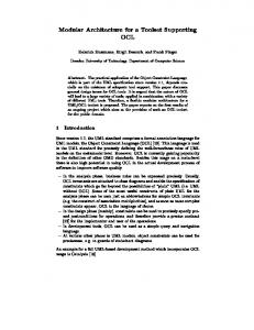
2 Modular VLSI Implementation Architecture The modular VLSI architecture presented in this paper is designed around multiple so-called Connection Processors (CP) as shown in Figure 1. The architecture distinguishes between the receive and send part in order to allow concurrent processing and, thus, to increase system throughput. In addition to multiple CPs, a memory unit and a memory management unit are implemented for the send and the receive side, respectively. The VLSI implementation architecture forms the connection between the network unit, which, e.g., handles the layers below the media access interface in 802.x LANs or ATM and lower layers in B-ISDN, and a host such as a workstation. Therefore, the application component in Figure 1 includes the host and an appropriate interface (e.g., DMA interface) for data transfer between host memory and send/receive RAM. To avoid buffering of data within the send/receive memory, the user data may also be copied directly from the network component into the workstation memory. The basic architecture is similar to [6]. The CPs are responsible for implementing the transport protocol of the communication subsystem. As long as enough free processing power of the CPs is available, a connection can be mapped onto a CP. However, parallelism in protocol implementation is not the major issue addressed in this paper. Proper embedding in a subsystem architecture including system functions, such as memory management, is extremely important to high performance communication subsystems. In order to process packets at extremely high rates as it may be needed, e.g., in servers inside gigabit networks, we propose the implementation of various VLSI components. The architecture (cf. Figure 1) consists of two data memories, for the receive side (receive RAM) and for the send side (send RAM), respectively. They are managed by specialized memory management units (E-MMUs). The network unit, the applications, and the CPs can access the data memories via the E-MMUs. The use of pointers avoids data copies during protocol processing. Operations on the memory, such as segmentation/reassembly and allocation/deallocation, are completely handled by the E-MMUs. Applications may read and write data via the E-MMUs. A key feature of the architecture is the replication of identical CPs similar to [6]. They include registers, arithmetic logical units (ALUs), timers, and other components required in a protocol implementation. The main purpose of the remaining components (management, A_MUX, N_MUX, N_DMX) is the distribution and collection of relevant information. Received data is divided into user data and a protocol header by the E-MMU. User data is written into the receive RAM. The protocol header together with a reference to the user data is delivered to the N_DMX that forwards it to an appropriate CP.
application management
A_MUX
receive
send E-MMU
...
CP
CP
E-MMU
RAM
RAM
N_MUX
N_DMX
network unit Figure 1: Modular VLSI Implementation Architecture The N_MUX collects protocol headers and references to user data to be sent to the network. The CPs cooperate with an application component via management and A_MUX. The manager maps a request for connection establishment onto a CP, which then is responsible for handling that connection properly. The mapping information is distributed to the A_MUX, N_MUX, and N_DMX. The four components management, A_MUX, N_MUX, and N_DMX are connected to the CPs via dedicated busses. The connections between CPs and E-MMUs are used for issuing CP-commands to the E-MMUs and receiving corresponding responses. In the subsequent section, the main components of the architecture, the E-MMU and the CP, are explained in some detail.
3 Extended Memory Management Unit Memory management is one of the most time-critical system tasks of a communication subsystem. For efficient memory management, special data structures to allow simple implementation in hardware are required. These data structures have to be designed to reduce data movement to a minimum, especially in the case of segmentation and reassembly. Because several external components (application - connection processor - network unit) use the same data structures for memory management, management and access to those data structures have to be easily controlled to avoid any inconsistencies and conflicts. Conflicts may be caused by multiple processing units concurrently accessing common data structures. In our approach, buffers and segments are the basic units for memory management. A buffer is a certain portion of consecutive, but not necessarily completely filled memory (Figure 2). A segment consists of one or more buffers.
buffers segment
first
segment descriptor
buffer descriptor
buffer descriptor
last
buffer descriptor
header
user data
user data
Figure 2: Data Structures for Efficient Memory Management So-called descriptors are used to describe the content of segments and buffers. They carry information such as memory addresses, reference counters, length values etc. The buffer descriptor contains information to describe the beginning and the end of the buffer, as well as the start and length of the buffer's data. The segment descriptor describes the segment by the first and the last buffer, and the total length of data over all buffers. Because of segmentation (e.g., if the packet to segment consists of a single buffer) a buffer must be able to be part of several segments simultaneously. Therefore, the segment descriptor needs information about the beginning of its own buffer data in a buffer shared with other segments. Also, the buffer descriptor has a reference counter of segments to which it belongs. The segments and buffer descriptors themselves are collected in simply linked lists. The internal architecture of the E-MMU is shown in Figure 3. The various components are interconnected with a crossbar dependent on the operations triggered by external components, an application, the connection processors, or the network unit, respectively. External components are interconnected via special interface components to the E-MMU. The data memory and the descriptor memory are also interconnected by such an interface. The separation of header and user data is reflected in the E-MMU-architecture. User data must be allocated from the data memory. The header memory is usually located in the connection processor to enable direct and fast access of the connection processor to the protocol headers. Headers are passed to a demultiplexer component (N_DMX), that delivers incoming headers to the appropriate connection processor. Outgoing headers are received from a multiplexer component (N_MUX) and passed to the network unit. However, the architecture would also be able to manage a separated header memory to store the protocol headers of the complete transport subsystem. Because user data usually have a variable length, buffer management may be very complex. To reduce the amount of wasted memory and to allow fast operations, we decided to implement the buddy algorithm for managing user data. The data structures required for implementing the algorithm are stored in an internal memory of the data MMU. The buddy algorithm provides data buffers with a length of 2k bytes. If a data buffer with a length of m is
required, a buffer with the size of 2p is allocated with 2p-1 < m ≤ 2p . If there is no appropriate buffer with the size of 2p, an appropriate buffer is generated by dividing a buffer with the length of 2p+1 into two buffers of size 2p. The fact that the buffer addresses differ in a certain bit only simplifies buffer release. If both pieces of size 2p have to be released, they can easily combined to a buffer of size 2p+1. The buddy algorithm is useful to provide fast and efficient memory management. Furthermore, it reduces wasted memory, which is a problem when single fixed size buffers should be used, e.g., for large AAL PDUs, and it avoids fragmentation of the memory. The descriptors reside in the descriptor memory. Because the size of a descriptor is fixed in contrast to a portion of user data, its management is much more simple than the management of user data. The descriptor memory is managed by the descriptor MMU using a stack, that contains a set of memory addresses, in an internal memory. Each memory address refers to a fixed size memory block. A memory address is taken from the stack to allocate a descriptor, while the address is pushed to the stack for release. E-MMU data memory
data MMU interface application
descriptor memory
segmentation/ reassembly
descriptor MMU
descriptor functions
crossbar with crossbar control
connection processor
network unit
header memory in connection processor
N_MUX/ N_DMX
Figure 3: Architecture of the Extended Memory Management Unit (E-MMU) If an external component, such as the network unit, allocates a data memory block, several processing steps have to be performed. First, the desired memory size must be allocated by the data MMU. Second, a buffer descriptor must be allocated by the descriptor MMU. To initialize the buffer descriptor, the address of the allocated data memory must be written into a reserved field of the buffer descriptor. Functions for initialization, allocation, and release are implemented within the descriptor function block.
Another advantage of the described data structures is the facility to efficiently support segmentation and reassembly procedures. Segmentation and reassembly can be performed arbitrarily often without copying of user data by manipulating the segment and buffer descriptors only. For segmentation, the references within the descriptors have to be adapted and new descriptors must be allocated to generate segments. For reassembly, the segments have to be combined and, thus, segment descriptors must be released. All these actions must be initiated by the crossbar control. The crossconnect also interconnects the internal components to perform the operation required by an external component. Generally, the architecture is based on a modular decomposition of independent internal components. The components can collaborate with each other and are able to operate in parallel. The crossbar allows concurrent interconnections among the internal components and, thus, operations simultaneously triggered by external components can be performed concurrently. Therefore, the actions resulting from several concurrent operations must be coordinated to avoid inconsistencies. The E-MMU provides the following operations to write or read to the user data memory or the descriptor memory, to allocate and release segment and buffer descriptors, to allocate and release a certain number of bytes of the data memory, and to support segmentation/reassembly functions: command memory_read
input parameter
output parame- comment ter type, priority, memory word read from memory offset, address
memory_write
type, priority, offset, address, data
write to memory address
get_segment_descriptor free_segment_descriptor address
address
get_buffer_descriptor free_buffer_descriptor
address
free_descriptors
address
get_data_memory
number
free_data_memory
address
segment
address, segment_size
address_list
reassemble
address_list
address
address
allocate segment descriptor release segment descriptor allocate buffer descriptor release buffer descriptor release all descriptors of a segment allocate data buffer release data buffer segmentation support by manipulation of the descriptors reassembly support by manipulation of the descriptors
Although, the E-MMU provides an interface to manipulate user data, access to the user data by the protocol processors should be avoided. Necessary data manipulation functions such as checksum calculation or presentation conversion functions should be performed while copying the data between the network interface and the send/receive memory or while copying between the application component and the send/receive memory, respectively.
4 Connection Processor The main components inside a Connection Processor are the FSM processing units (FSM_i) that perform all protocol functions. The FSMs of a formal protocol specification can be mapped onto these processing units (e.g., protocol and interface FSMs of PATROCLOS or single FSMs of standard protocols). All FSM processing units work independently; they communicate via asynchronous signals, thus, enabling concurrency among different protocol functions. FSMs may use global or local accessible timers. In case of global accessible timers, multiple FSMs can issue commands (e.g., start, restart) to such timer components. In addition, there is a global accessible ALU to manipulate registers that store variables used by more than one FSM (e.g., c.Cntl in XTP, a flag set by three different FSMs if sending a control packet is desired). FSMs issue a command to the ALU that performs the required operation on the data and may return a result (e.g., in case of comparisons). To guarantee consistency, FSMs can access the registers through the ALU only. A specialized connecting element, e.g., a crossconnect, interconnects all components inside the connection processor and external components (E-MMU, MUX, DMX). Due to its modular design, this architecture can be adapted to different protocols. For example, XTP needs global variables and global accessible timers and, therefore, a global accessible ALU with registers and global timer unit(s) are required. PATROCLOS needs local variables and local timers only and, thus, the global components are not required. management
A_MUX
FSM_2
FSM_1
send E-MMU
receive E-MMU timer component
... ALU component
FSM_n
N_MUX
CP
N_DMX
Figure 4: Internal Structure of a Connection Processor
Components (e.g., FSMs) internal to the CP are interconnected via a connecting element. To provide a maximum of flexibility they are designed with identical interfaces. The input signals consist of a 32 bit data bus di , a request line ri , and an acknowledge line ai. Valid data is signaled via ri = 1. The component shows its readiness to receive the data via ai = 1. After transmitting all data to the component, the sender pulls down ri to 0. The output interface consists of corresponding signals: a 32 bit data bus do , a request line ro , and an acknowledge line ao . The protocol to transmit data to another component corresponds to the input interface.
32 di ri ai
32
CP-component
do ro ao
Figure 5: General CP Component Design 4.1 Connecting Component The connecting component may provide two separated unidirectional connections to every component inside the processor and to the external units. Two different connections should not interfere each other due to blocking. Therefore, one could realize the connecting component via a crossbar switch. Dedicated or seldom used connections could be multiplexed. Due to the internal design of the connected components, the connecting component itself does not need storage components such as queues. 4.2 Finite State Machine Every communication protocol specification consists of one or more finite state machine(s). In this paper, we mainly address protocols, which are specified as a set of multiple highly independent FSMs. Examples are XTP [2], SNR [7] and Patroclos [8], [9]. Each of these protocols is able to be implemented on the VLSI implementation architecture by implementing the appropriate FSM processing components.
di ri ai
queue
FSM
do ro ao
local ALU Figure 6: Finite State Machine Component An FSM processing component (cf. Figure 6) forms the basis for an implementation of parallel FSMs. Each FSM processing unit consists of local registers, a local ALU, and a con-
trol unit. A local ALU is customized to individual requirements of the corresponding FSM. It can be as simple as an adder or as complex as a management unit for dynamic lists. To decouple FSMs from other units inside a Connection Processor, each FSM utilizes a separate input queue. Commands to an FSM will be inserted into this queue, thus providing asynchronous communication among the FSMs. 4.3 Timer Component Several protocol functions, such as retransmission, reassembly, and connection management, require timer operations. In most implementations architectures, timers are supported by the operating system. However, this support often forms a major performance bottleneck [10]. Therefore, the modular VLSI implementation architecture comprises a dedicated timer component. According to the performance needs either this component can be scaled or several identical components can be implemented. The timer component (cf. Figure 4) manages a dynamic list of timers. Several commands exist to manipulate the list: command
input parameter
create
conn_id, time_out, timer_id receiver
set reset delete read alarm
output parameter comment create a new timer entry in the timer list; return the timer identification conn_id, timer_id, set an existing timer to a new timetime_out out value conn_id, timer_id reset an existing timer to its original time-out value conn_id, timer_id delete an existing timer conn_id, timer_id read the actual value of an existing timer timer_id time-out has occurred
The parameters are defined as follows. conn_id indicates the unique identification of the connection the timer belongs to, time_out is a 32 bit value indicating the time-out value. The appropriate receiver(s) of an alarm are listed in the receiver vector. The timer_ids are managed by the global accessible timer itself. The resolution of the global accessible timer is 100 ns, the maximum time-out value is, therefore, greater than 7 minutes. 4.4 ALU Component A global ALU (cf. Figure 4) is similar to an ALU of a general purpose processor. It implements standard operations, such as OR, XOR, ADD, SUB, SHR, SHL, and MULT. Multiplication (MULT) is the most complex operation of such an ALU, however, it is needed for several protocol functions. The ALU behaves like a coprocessor and works asynchronously. It consists of an input queue and the ALU itself (cf. Figure 7). The ALU comprises several registers. To guarantee data consistency, global data is stored in the registers and can be accessed via the ALU only.
32 di ri ai
32
queue
32
ALU
do ro ao
32
registers Figure 7: ALU Component
5 VLSI for Retransmission Support One of the most complex ALU in a Connection Processor is retransmission support. It manages information for retransmission and, therefore, can be used as a local ALU for a retransmission FSM. Enhanced transport protocols, such as XTP, support selective retransmission due to the unacceptable overhead of a go-back-n mechanism. Information needed for selective retransmission are gaps representing spans of bytes not yet correctly transmitted. The sender has to retransmit the bytes indicated by a gap if the service guarantees correct and complete transmission. The processing overhead associated with handling retransmissions and the required data structures may be extremely high compared to other protocol functions. As an example some data about an XTP implementation on Digital Alpha Computers (150 MHz, 6.66 ns cycle time). The function to insert a new gap in a list needs in the best case 824 4-byte commands and takes, therefore, 5.4 µs. The best case occurs if the new entry can be inserted at the beginning of the list. If the new entry has to be inserted after the first 10 entries it needs 4054 commands or 27.03 µs due to the search operations in the list. These calculations assume that the processor is not interrupted during execution of this function and all data is stored in the fast processor cache. XTP was implemented using C without special inline assembly code. Note that the protocol has been implemented without any code optimizations on C or assembly language level. If data is sent at a rate of 1 Gbit/s this results in more than 122,000 1024-byte packets per second. If the retransmission of each packet has to be controlled this results in a new entry in the list in less than 10 µs. Clearly, retransmission support forms a time critical task. Therefore, we are implementing dedicated VLSI support for this task. The retransmission support presented in the following can handle negative selective, positive selective, and positive cumulative acknowledgement and can be used for gaps in received data to support the acknowledgement function or for gaps in transmitted data to support the retransmission mechanism. The ALU has a set of commands to set, delete, insert, and read gaps.
5.1 Logical Representation of Data A dynamic linked list stores gaps of transmitted data in the following representation: [seq_no_1, seq_no_2] with seq_no_1 and seq_no_2 representing the beginning and ending of a gap. These gaps are connected via linked lists (cf. Figure 8).
conn_id 0 1 2
seq_no_1 32476
16342 46317
3456
. . .
seq_no_2 32538
17023 47212
. . . 3571
1002
5264
next
3
124
253 254 255 Figure 8: Logical Structure of Linked Lists for Retransmission Support 5.2 Operations of the Retransmission ALU The following table shows the operations supported by the specialized ALU. operation
input pa- output pa- comment rameters rameters conn_id, init_list initializes a new list for the connection seq_no conn_id with the initial sequence number seq_no, sets the error flag if conn_id is already in use conn_id close_list closes the list for connection conn_id, sets the error flag if the list does not exist conn_id, set_high_ack sets the high_ack register to the value of seq_no seq_no; sequence numbers less than high_ack have been already acknowledged shift_high_ack conn_id, shifts the high_ack register to high_ack + length length set_high_seq
conn_id, seq_no
shift_high_seq conn_id, length set_gap_1
conn_id, seq_no, length
sets the high_seq register to the value of seq_no; high_seq represents the highest sequence number in use shifts the high_seq register to high_seq + length inserts new entry (seq_no, seq_no + length); overlapping entries are automatically joined or deleted, respectively
set_gap_2
conn_id, seq_no_1, seq_no_2
analogous to set_gap_1, but the new entry is of the form (seq_no_1, seq_no_2)
del_gap_1
conn_id, seq_no,
deletes an existing entry, a part of an existing entry, or several existing entries, the deleted part is of the form (seq_no, seq_no + length); if necessary an entry is automatically divided into two new entries analogous to delete_gap_1, but the deleted part is of the form (seq_no_1, seq_no_2)
length
del_gap_2
conn_id, seq_no_1, seq_no_2
read_reg
conn_id, reg_id
cont
get_gap_1
conn_id,
seq_no,
ptr
length,
get_gap_2
conn_id, ptr
reads the contents cont of the register reg_id (e.g. high_ack, high_seq, number_of_gaps)
reads the entry ptr points to; if ptr = 0, the first gap is read out, if next = 0 the entry repnext resented by (seq_no, length) is the last one, otherwise next point always to the next entry of the list seq_no_1, analogous to get_gap_1, but the entry is repseq_no_2, resented by (seq_no_1, seq_no_2) next
conn_id ∈ [0, 255]; seq_no, seq_no_1, seq_no_2, length, cont ∈ [0, 232-1]; reg_id ∈ [0, 15]; ptr, next ∈ [0, 216-1] Every operation sets the error flag if it failed due to memory overflow or violation of several conditions, such as high_ack ≤ seq_no ≤ high_seq and other range checking. 5.3 Implementation Architecture for Retransmission Support Figure 9 shows an overview of the internal structure of the ALU. The retransmission ALU consists of 5 memory banks (A through E) that store sequence numbers representing gaps (memory A and B), pointers of linked lists (memory C), and state information, such as connection identification, register number of an anchor element, and other flags indicating the state of a connection (memory D and E). The I/O-bus connects the input/output-port (32 bit) of the retransmission ALU with the 5 register banks (Ai through Ei, 0≤i≤3). From these registers data can be transferred to the memory. Two simple ALUs (ALU A, 32 bit and ALU D, 8 bit) perform operations like OR, XOR, AND, ADD, SUB, and NEG. Two specialized 32 bit modulo 232 comparators (comp A and comp B) perform fast comparisons needed for list operations. The ALUs and the comparators can work concurrently if no data dependencies exist. For the command set_gap_2, for example, first of all the command itself and the connection identification are read from the I/O-bus into the registers E and D, respectively. In the next two cycles the central control unit reads the sequence numbers (seq_no_1,
seq_no_2) into the registers A and B, respectively. After reading the complete command and several range checking operations the loop for searching the right position to insert the new entry in the list starts. Therefore, the first entry of the appropriate list is loaded into the registers A and B, respectively, and compared with the new entry. The loop terminates if the new entry fits, otherwise, the next entry is loaded and compared.
A
B
C
D
E
seq_no1 memory
seq_no2 memory
pointer memory
conn_id memory
flag memory
32
32
I/O
32
A0 A1 A2 A3
B0 B1 B2 B3
C0 C1 C2 C3
ALU A 32 bit
comp A 32 bit
comp B 32 bit
8 D0 D1 D2 D3
8 E0 E1 E2 E3
ALU D 8 bit
central control unit Figure 9: Structure of the Retransmission ALU 5.4 Microcode Examples of the Retransmission ALU To provide a maximum of flexibility all functions of the local ALU are translated into a sequence of microcode operations. These operations are specially adapted to the implementation architecture shown in Figure 9. The central control unit controls the microprogram via a special micro sequencer. Example microcode operations of the local ALU are listed in the following table. operations RMOVE S, D
comment move a complete row of entries from the registers or RAM into the registers or RAM. S, D ∈ {Ri, RAM; 0 ≤ i ≤ 3}, Rn = (An, Bn, Cn, Dn, En), S ≠D
AMOVE I/O, D ACLR D AINC S, D ADEC S, D AMOVE S, D AADD S, D ASUB S, D
move data from the I/O-bus into the register D; D ∈ {Ai, Bi; 0 ≤ i ≤ 3} clear register D; D ∈ {Ai, Bi; 0 ≤ i ≤ 3} S + 1 -> D; S, D ∈ {Ai, Bi; 0 ≤ i ≤ 3} S - 1 -> D; S, D ∈ {Ai, Bi; 0 ≤ i ≤ 3} S -> D; S, D ∈ {Ai, Bi; 0 ≤ i ≤ 3} S + D -> D; S, D ∈ {Ai, Bi; 0 ≤ i ≤ 3} S - D -> D; S, D ∈ {Ai, Bi; 0 ≤ i ≤ 3}
In addition, there are the microcode operations of the ALU D and complex comparison operations of the two comparators comp A and comp B. The operations of the ALUs and the comparators are always executed in parallel in one clock cycle. 5.5 Implementation Detail: A 32 bit modulo 232 comparator Due to the complexity of the complete design, only a selected part is presented in detail. This section shows the design of a 32 bit modulo 232 comparator (cf. comp A and comp B in Figure 9). Such a comparator is needed to compare three 32 bit values at the same time. This comparison is done while searching for the right position in the retransmission list to insert a new entry or to delete an existing entry. Due to the modulo 232 arithmetic and the need for fast search operations in the dynamic lists common comparators with only two inputs cannot be used. Four functions are calculated at the same time: le_le (a, b, c) = true ⇔ ((a ≤ c) ∧ (a ≤ b ∧ b ≤ c)) ∨ ((a > c) ∧ (a ≤ b ∨ b ≤ c)) le_lt (a, b, c) = true ⇔ ((a < c) ∧ (a ≤ b ∧ b < c)) ∨ ((a > c) ∧ (a ≤ b ∨ b < c)) lt_le (a, b, c) = true ⇔ ((a < c) ∧ (a < b ∧ b ≤ c)) ∨ ((a > c) ∧ (a < b ∨ b ≤ c)) lt_lt (a, b, c) = true ⇔ ((a < c) ∧ (a < b ∧ b < c)) ∨ ((a > c) ∧ (a < b ∨ b < c)) a, b, c ∈ IN mod 232; le: less or equal; lt: less than The complete architecture and its components are described with the standardized hardware description language VHDL [11]. This allows for simulation and synthesis based on the same language. library IEEE; use IEEE.std_logic_1164.all; use IEEE.std_logic_arith.all; entity MOD_KOMPA is port ( A, B, C : IN std_logic_vector (31 downto 0); le_le, le_lt, lt_le, lt_lt: OUT boolean); end MOD_KOMPA; architecture BEHAVIORAL of MOD_KOMPA is begin process (A,B,C) variable h1, h2, h3, h4, h5, h6 : boolean; begin h1 := A < B; h2 := A C; h5 := B < C; h6 := B