A VLSI Algorithm for Modular Multiplication/Division Marcelo E. Kaihara and Naofumi Takagi Department of Information Engineering Nagoya University Nagoya, 464-8603, Japan
[email protected]
Abstract We propose an algorithm for modular multiplication/division suitable for VLSI implementation. The algorithm is based on Montgomery’s method for modular multiplication and on the extended Binary GCD algorithm for modular division. It can perform either of these operations with a reduced amount of hardware. Both calculations are carried out through iterations of simple operations such as shifts and additions/subtractions. The radix-2 signed-digit representation is employed so that all additions and subtractions are performed without carry propagation. A modular multiplier/divider based on this algorithm has a linear array structure with a bit-slice feature and carries out an n-bit modular multiplication in at most b 2(n+2) c + 3 clock 3 cycles and an n-bit modular division in at most 2n+5 clock cycles, where the length of the clock cycle is constant and independent of n.
1 Introduction With the proliferation of Internet usage, there is an increasing necessity for PCs and mobile devices, such as PDAs, of having ability to manage several security protocols. Since processing of public-key cryptosystems requires huge amount of computation, there is a growing demand for developing dedicated hardware to accelerate this. In this paper, we propose a VLSI algorithm for modular multiplication/division with a large modulus. Modular multiplication with a large modulus is the basic operation in calculating modular exponentiation which is used to process public-key cryptosystems such as RSA [4]. One of the efficient methods for calculating the modular multiplication is by using Montgomery’s multiplication algorithm [3]. Several implementations of the algorithm have been proposed [1]. On the other hand, modular division with a large modulus is used in decryption of public-key cryptosystems such as ElGamal [2]. It can be calculated by using the extended
Binary GCD algorithm which is suited for binary arithmetic [5]. Since PCs and mobile devices do not seem to process more than one cryptosystem simultaneously, we combine multiplier and divider so that the hardware requirement is reduced by making large part of the circuit be shared by the two operations. In the VLSI algorithm to be proposed, multiplication is based on Montgomery’s algorithm and division is based on the extended Binary GCD algorithm. The algorithm is accelerated by introducing redundant representation in all additions/subtractions so that they are carried out in constant time independent of the length of the operands. Almost all the components in the VLSI algorithm are shared reducing considerably hardware requirements. A modular multiplier/divider based on the algorithm has a linear array structure with a bit-slice feature and is suitable for VLSI implementation. The amount of hardware of an n-bit modular multiplier/divider is proportional to n. It performs an n-bit modular multiplication in at most c + 3 clock cycles and an n-bit modular division in b 2(n+2) 3 at most 2n + 5 clock cycles where the length of clock cycle is constant independent of n. In the next section, we explain the extended Binary GCD algorithm and Montgomery’s multiplication algorithm. In Section 3, we propose a VLSI algorithm for modular multiplication/division. In Section 4, we discuss several aspects about implementation. In Section 5, we present the concluding remarks.
2 Preliminaries 2.1 Extended Binary GCD Algorithm for Modular Division Extended Binary GCD Algorithm is an efficient way of calculating modular division [5]. Consider the residue class field of integers with an odd prime modulus M . Let X and
Y (6= 0) be elements of the field. The algorithm calculates Z(< M ) such that Z ≡ X/Y (mod M ). It performs modular division by intertwining a procedure for finding the modular quotient with that for calculating gcd(Y, M ). The algorithm is based on the following facts: if A is even and B is odd, then gcd(A, B) = gcd(A/2, B); if A and B are both odd, then either A + B or A − B is divisible by 4; in this case, if A + B is divisible by 4, then gcd(A, B) = gcd((A + B)/2, B), (A + B)/2 is even and |(A+B)/2| ≤ max(|A|, |B|); otherwise A−B is divisible by 4, gcd(A, B) = gcd((A−B)/2, B), (A−B)/2 is even and |(A − B)/2| ≤ max(|A|, |B|). We show the algorithm below. Note that A and B are integers and are allowed to be negative. δ represents α − β, where α and β are values such that 2α and 2β indicates the minimums of the upper bounds of |A| and |B| respectively. [Algorithm 1] (Extended Binary GCD Algorithm) Function: Modular Division Inputs: M : 2n−1 < M < 2n X, Y : 0 ≤ X < M , 0 < Y < M Output: Z ≡ X/Y mod M Algorithm: A := Y ; B := M ; U := X; V := 0; δ := 0; while A > 0 do while A mod 2 = 0 do A := A/2; U := U/2 mod M ; δ := δ − 1; end while if δ < 0 then T := A; A := B; B := T ; T := U ; U := V ; V := T ; δ := −δ; end if if (A + B) mod 4 = 0 then q = 1; else q = −1; end if A := (A + qB)/2; U := (U + qV )/2 mod M ; end while if B = 1 then Z := V ; else /* B = −1 */ Z := M − V ; end if output Z as the result; To calculate U/2 mod M , the algorithm examines the least significant bit of U to determine whether it is even or odd. If it is even, the algorithm performs U/2, otherwise it performs (U + M )/2. In this way, modular reduction is accomplished by a simple shift operation. It can easily be shown that the equivalences V × Y ≡ B×X (mod M ) and U ×Y ≡ A×X (mod M ) always hold. Since gcd(Y, M ) = 1, when A = 0, B is 1 or −1. Hence, in the final step Z × Y ≡ X (mod M ) holds, and Z is the quotient of X/Y modulo M .
2.2 Montgomery’s Modular Multiplication Algorithm Montgomery introduced an efficient algorithm for calculating modular multiplication [3]. Consider the residue class ring of integers with an odd modulus M . Let X and Y be elements of the ring. Montgomery’s modular multiplication algorithm calculates Z(< M ) such that Z ≡ XY r−1 (mod M ) where r is an arbitrary constant relatively prime to M . The value of r is usually set to 2n when the calculations are performed in radix-2 with an n-bit modulus M . The radix-2 Montgomery’s multiplication algorithm is described below. We use the same notation as in the extended Binary GCD algorithm to emphasize the similitude of these algorithms. [Algorithm 2] (Montgomery’s Multiplication Algorithm) Function: Montgomery’s Modular Multiplication Inputs: M : 2n−1 < M < 2n X, Y : 0 ≤ X, Y < M Output: Z ≡ XY 2−n mod M Algorithm: A := Y ; U := 0; V := X; for i = 1 to n if A mod 2 = 0 then q = 0; else q = 1; end if A := (A − q)/2; U := (U + qV )/2 mod M ; end for if U ≥ M then Z := U − M ; else Z := U ; end if output Z as the result; Note that U is always bounded by 2M throughout all iterations. Therefore, the last correction step assures that the output is correctly expressed in modulo M .
3 A VLSI Algorithm for Montgomery’s Modular Multiplication and Modular Division We propose a VLSI algorithm that performs Montgomery’s modular multiplication and modular division, which is efficient in execution time and hardware requirements.
3.1 Use of a Redundant Representation We assume that the input modulus M is an n-bit binary odd number that satisfies the condition 2n−1 < M < 2n . We also assume that the input operands X and Y and the
output result Z are n-digit radix-2 signed-digit (SD2) integers in the range (−M, M ). The SD2 representation uses the digit set {¯1, 0, 1} where ¯1 denotes −1. An n-digit SD2 integer A = [an−1 , an−2 , · · · a0 ] (ai ∈ {¯ 1, 0, 1}) has the value Pn−1 i a · 2 . Addition of two SD2 numbers can be peri=0 i formed without carry propagation. We use the addition rules for SD2 numbers shown in table 1 [6]. The addition is accomplished by first calculating the interim sum ui and the carry digit ci and then performing the final sum si = ui + ci−1 for each i. To calculate si , we just have to check the digits ai , bi and their preceding ones. All the digits of the result can be computed in parallel. The negation of an SD2 number can be done simply by changing the signs of all nonzero digits in it. Subtraction can be performed through negation and addition in one step. We require a carry-propagate addition to convert an SD2 number to the binary representation. Table 1. The rules for adding binary SD2 numbers a i bi
ai−1 bi−1
ci
ui
00
–
0
01/10
neither is ¯ 1
1
0 ¯ 1
01/10 ¯ 10 ¯ 01/
at least one is ¯ 1 ¯ neither is 1
0
0¯ 1/¯ 10
at least one is ¯ 1
11 ¯1 ¯ 1
–
1¯ 1/¯ 11
0 ¯ 1
1 ¯ 1 1 0
–
1 ¯ 1
–
0
0
0
We represent the internal variables A, B, U and V in n-digit SD2 representation so that all basic operations are carried out in constant time independent of the lengths of the operands by a combinational circuit. In applications such as exponentiation, chained multiplications are required. To remove time-consuming SD2 to binary conversion in each multiplication, we allow the input operands X and Y as well as the output result Z be expressed in the same redundant representation so that the output can be directly fed into the inputs. Note that the operands X, Y can still be given in ordinary binary representation.
3.2 Division Mode We follow the structure of the VLSI algorithm for modular division based on the Binary GCD algorithm [5] and further accelerate it.
This algorithm [5] performs all basic operations in constant time independent of n by a combinational circuit. This algorithm implements the ‘while’ loop introducing P which represents a binary number of n + 2 bits and indicates the minimum of the upper bounds of |A| and |B|, i.e., min(2α , 2β ). Note that P has only one bit in 1 and the rest in 0. In this way, the termination condition check, A = 0, that may require an investigation of the whole bits of A is replaced by a check of P = 1 which can be carried out by just looking at the least significant bit of P , i.e. p0 . A binary number D and a flag s (∈ {0, 1}) are introduced to implement δ. D has n bits of length and has the value s D = 2(−1) ·δ . Note that this variable also has only one bit in 1 and the rest in 0. In this way, the decrement of δ, δ := δ − 1, which may require a long borrow propagation is replaced by a one-bit shift of D. The calculation of T /2 modulo M is implemented by the operation M HLV (T, M ). It is carried out by performing T /2 or (T + M )/2 accordingly as T is even or odd. Note that only the least digit of T has to be checked to determine whether it is even or odd. The calculation of T /4 modulo M is implemented by the operation M QRT R(T, M ). It is carried out by performing the following calculations: If M (mod 4) is 1, it performs T /4 or (T − M )/4 or (T + 2M )/4 or (T +M )/4, accordingly as T (mod 4) is 0, 1, 2 or 3. If M (mod 4) is 3, it performs T /4 or (T + M )/4 or (T + 2M )/4 or (T − M )/4, accordingly as T (mod 4) is 0, 1, 2 or 3. Since M is an ordinary binary number, addition of M or −M or 2M in M HLV and M QRT R is simpler than the ordinary SD2 addition. For the details of the simpler SD2 addition, see, e.g., [7]. The operation U/2 modulo M that is performed with the operation A := A/2 in Algorithm 1 when A is divisible by 2, is implemented with the operation M HLV (U, M ). Since, A := (A + B)/2 (or A := (A − B)/2) is always divisible by 2, the algorithm combines this calculation with its succeeding one A := A/2 obtaining A := (A + B)/4 (or A := (A − B)/4) and its corresponding operation U := (U + V )/4(modM ) (or U := (U − V )/4(modM )). The latter operation is implemented by using M QRT R(U +V, M ) (or M QRT R(U −V, M )). The calculations of A := (A + B)/4 and M QRT R(U + V, M ) (or A := (A − B)/4 and M QRT R(U − V, M )) are also combined with their preceding swap of A and B and that of U and V , respectively. All the results of these basic operations are always in the range from −M to M and no over-flow occurs. In order to accelerate the calculation, for the case that A is divisible by 4, instead of performing A/2 and U/2 modulo M in two different steps, we modify the algorithm by grouping two of each operation into the calculations of A/4 and U/4 modulo M . We perform the latter calculation by using M QRT R(U, M ).
3.3 Multiplication Mode We implement the while loop by using the same P as in the division case. In Algorithm 2, A and V are initialized with the values of Y and X. U is used to store the partial products and it is initialized with the value 0. The algorithm examines the least significant bit of A to determine whether V has to be added. Then it performs a division of U by 2 modulo M and A is shifted down one position. To accelerate the calculation, we modify this algorithm so that it processes two digits at a time. We examine the least two significant digits of A, i.e. [a1 a0 ]. If [a1 a0 ] = [00], we perform U/4 modulo M and shift down A two digit positions. If [a1 a0 ] = [10] or [¯ 10], we perform U/2 modulo M and shift down A only one position. The 1 or ¯1 digit that is shifted into the least significant digit position is processed in the next iteration. The operations U/4 modulo M and U/2 modulo M can be accomplished by performing M HLV (U, M ) and M QRT R(U, M ) respectively. If [a1 a0 ] = [01] or [0¯ 1], we perform M QRT R(U + V, M ) or M QRT R(U − V, M ) accordingly, and we shift down A two digit positions. If [a1 a0 ] = [1¯ 1] or [¯ 11], we ¯ convert it into [01] or [01] so that we can perform the same operations as the previous case. If [a1 a0 ] = [¯ 1¯ 1] or [11], we convert it into [01] or [0¯ 1] and add −4 or 4 to A so that this case is also reduced to the previous ones. In this way, all the operations can be accomplished with shifts, M HLV and M QRT R, and all the results are always bounded in magnitude by M . The Montgomery’s constant r is now 2n+2 . To make use of the same decision rule as in the division, we initialize B with its least significant digit in ¯1. In this way, when the least significant digit of A has value 1, A+ B = 0 mod 4. The correction of adding −4 or 4 can be done introducing the digit ¯ 1 in the third least significant bit of B, i.e. b2 . The conversions and corrections are performed in the algorithm by rewrite(a2 , a1 , b2 ) and the rules are summarized in table 2. Note that when [a1 , a0 ] = [11], these digits are replaced by [0¯ 1] and subtraction is performed. Therefore, the correction of adding 4 is performed by introducing the value ¯ 1 in b2 .
3.4 The VLSI Algorithm The VLSI algorithm is presented here. In the following, {C1, C2} means that two calculations, C1 and C2, are performed in parallel. [Algorithm 3] (A VLSI Algorithm for Montgomery’s modular multiplication and modular division) Function: Montgomery’s Modular Multiplication and
Table 2. Conversion rule for rewrite (a1 , a0 , b2 ) a1
a0
b2
a1
a0
meaning
¯ 1 ¯ 1
¯ 1
¯ 1
−4 + 1
0
0 ¯ 1
1
0
0−2
¯ 1 0
1 ¯ 1
0 0
0 0
0 ¯ 1 ¯ 1
0
0
0
0
0
0
0
1 ¯ 1
0
0
1
0+1
1
0
0
1
0+1
1
0
0 ¯ 1
0+2
1
0 ¯ 1
1
1
0
0−1 0−1
4−1
Modular Division Inputs: M : 2n−1 < M < 2n X, Y : −M < X, Y < M Output: mode = 0 : Z ≡ XY 2−(n+2) mod M mode = 1 : Z ≡ X/Y mod M Algorithm: Step 1: A := Y ; P := 2n+1 ; s := 1; D := 1; M := M ; if mode = 0 then B := 1; U := 0; V := X; else B := M ; U := X; V := 0; end if Step 2: while p0 6= 1 do if mode = 0 then rewrite (a1 , a0 , b2 ); end if if [a1 a0 ] = 0 then /* A mod 4=0 */ A := A >> 2; U := M QRT R(U, M ); if s = 0 then if d1 = 0 then D := D >> 2; if d0 = 1 then s := 1; end if else P := P >> 1; s := 1; end if else /* s = 1 */ D := D > 2; else P := P >> 1; s := 0; end if end if elseif a0 = 0 then /* A mod 4=2 */ A := A >> 1; U := M HLV (U, M ); if s = 0 then D := D >> 1; if d0 = 1 then s := 1; end if else /* s = 1 */ D := D > 1; else /* A mod 4=1 or A mod 4=3 */ if ([a1 a0 ] + [b1 b0 ]) mod 4 = 0 then q = 1 else q = −1 end if if mode = 0 or s = 0 or d0 = 1 then
A := (A + qB) >> 2; U := M QRT R(U + qV, M ); if s = 1 then if mode = 0 and p1 = 0 then P := P >> 2; else P := P >> 1; if p0 = 1 then s = 0 end if end if D := D > 1; if d0 = 1 then s := 1; end if end if else /* mode = 1 and s = 1 and D > 1 */ {A := (A + qB) >> 2, B := A}; {U := M QRT R(U + qV, M ), V := U }; s := 0; D := D >> 1; if d0 = 1 then s := 1; end if end if end if end while Step 3: if mode = 0 and s = 1 then U := M HLV (U, M ); else if mode = 1 and [b1 b0 ] mod 4 = 3 then V := −V ; end if end if Step 4: if mode = 0 then Z := U ; else Z := V ; end if output Z as the result;
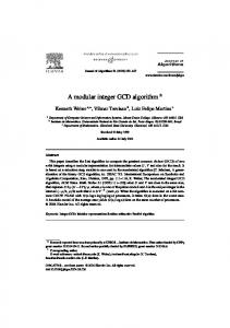
In division mode, i.e. mode= 1, when A mod 4 = 0, A is shifted down two digits and M QRT R(U, M ) is performed. Note that when P = 2 and a0 = 0, an extra 0 digit is processed together. However, since these operations only updates the values of A and U , this calculation does not affect the final result nor does increase the number of iterations needed. No special consideration has to be taken for the termination condition. Note also that in the algorithm, δ is represented with the values of D and s. We take as convention to represent δ = 0 with D = 1 and s = 1. In Step 3, B is 1 when B mod 4 = 1 and it is −1 otherwise, i.e., when B mod 4 = 3. When B = −1, V is negated in the SD2 system. Fig. 1 shows an example of a modular division, −115/249 mod 251 = −68 mod 251 = 183 where n = 8 by [Algorithm 3]. The leftmost column shows which calculations have been carried out. For example, ‘(A − B)/4,A’ means that { A := (A − B)/4, B := A } and { U := M QRT R(U − V, M ), V := U } have been carried out.
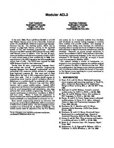
In multiplication mode, i.e mode=0 the flag s is set to 1 and it remains in this value until the end of Step 2. In the case that P = 2, and the corresponding operation to be performed involves two digits shift, we shift P only one position to mark the end of the loop and reset the flag s to 0. At this point, n + 2 digits of A are processed so no extra calculations are needed. In the case that P = 2, and the corresponding operation to be performed involves only one digit shift, P is shifted one position and the loop finishes leaving one digit of A unprocessed. This is the same case as having P = 4 with operations involving two digits shifts. The flag s is left in the value 1 indicating that an extra operation is needed in Step 3. It can be shown that this unprocessed digit is always 0, so we only need to perform M HLV (U, M ) at the end. In this way, all the n + 2 digits of A are always processed and the Montgomery’s constant has the value r = 2n+2 Proposition 1: Let Y be expressed in SD2 representation with n bits of length such that −M < Y < M , and M be an n-bit binary number that satisfies the condition 2n−1 < M < 2n . If Algorithm 3 is used with this input and Step 2 finishes leaving the topmost significant bit of A unprocessed, this digit is always 0. Proof: At initialization time, the value of Y is copied into A. Suppose the case that A is positive and an−1 = 1, this digit can be transformed into [10] or into [1¯1] when A + B or A − B is performed following the addition rules of SD2 numbers described in table 1. For the former case, the digits [10] can in turn be transformed into [1¯10]. Further expansion does not occur when the most significant digit is followed by ¯1. Now, consider the case that n − 1 bits of A have been processed and we are about to process the next two of the remaining three bits. A can have its bits [a2 , a1 , a0 ] = 1¯10 or 1¯1¯1. No other possibilities are left because of the restriction of |A| < M . In the former case, A is shifted by only one position leaving the other two bits to be processed in the next iteration. In fact, these bits 1¯1 are recoded into 01 and they are processed together in the next iteration. No extra calculation is needed. In the latest case, the least significant two digits ¯1¯1 of A are recoded into 0¯1 and processed together. The generated carry digit ¯1 is subtracted from A so that the most significant bit of A that has been left is cancelled and reset to 0. Similarly, when A is negative and an−1 = ¯1, this digit can be transformed into [¯11] and no further expansion occurs. Fig. 2 shows an example of a Montgomery’s multiplication , −115 × 249 × 2−10 mod 251 = 137 where n = 8 by [Algorithm 3]. The leftmost column shows which calculations have been carried out. For example, ‘A >> 1’ means that A >> 1 and U := M HLV (U, M ) have been carried out and ‘(A + B) >> 2’ means that (A + B) >> 2 and U := M QRT R(U, M ) have been carried out. In this
(A + B)/4,B (A + B)/4,A A/2,B (A + B)/4,A (A − B)/4,B (A − B)/4,A A/4,B (A + B)/4,A (A + B)/4,B (A + B)/4,B (A + B)/4,A (A − B)/4,B A/4,B −V
mode = 1, M A 111111¯ 1¯ 1 (249) 01111101 (125) 01011110 (94) 00101111 (47) 00101011 (43) 000000¯ 11 (−1) 0000¯ 1¯ 100 (−12) 000000¯ 1¯ 1 (−3) 0000000¯ 1 (−1) 0000000¯ 1 (−1) 0000000¯ 1 (−1) 0000000¯ 1 (−1) 00000000 (0) 00000000 (0)
¯ ¯ SD (−115), Y = [111111¯ = [1111011]2 (251), X = [10010 101] 1¯ 1]SD (249) B P D s U ¯ 11111011 (251) 1000000000 0000000001 1 10010¯ 101 (−115) 11111011 (251) 0100000000 0000000010 1 00100010 (34) 01111101 (125) 0100000000 0000000001 1 10001¯ 110 (134) 01111101 (125) 0010000000 0000000010 1 010001¯ 11 (67) 00101111 (47) 0010000000 0000000001 1 01011000 (88) 00101111 (47) 0001000000 0000000010 1 01000100 (68) 000000¯ 11 (−1) 0001000000 0000000001 1 010000¯ 11 (63) 000000¯ 11 (−1) 0000010000 0000000100 1 0¯ 11¯ 101¯ 1¯ 1 (−47) 000000¯ 1¯ 1 (−3) 0000010000 0000000010 0 01000100 (68) 000000¯ 1¯ 1 (−3) 0000010000 0000000001 1 01000100 (68) 000000¯ 1¯ 1 (−3) 0000001000 0000000010 1 01000100 (68) 0000000¯ 1 (−1) 0000001000 0000000001 1 01000100 (68) 0000000¯ 1 (−1) 0000000100 0000000010 1 00000000 (0) 0000000¯ 1 (−1) 0000000001 0000001000 1 00000000 (0)
V 00000000 00000000 00100010 00100010 010001¯ 11 010001¯ 11 01000100 01000100 0¯ 11¯ 101¯ 1¯ 1 0¯ 11¯ 101¯ 1¯ 1 0¯ 11¯ 101¯ 1¯ 1 01000100 01000100 01000100 0¯ 1000¯ 100
(0) (0) (34) (34) (67) (67) (68) (68) (−47) (−47) (−47) (68) (68) (68) (−68)
Z = [0¯ 1000¯ 100]SD (−68)
Figure 1. A modular division by [Algorithm 3]
(A + B) >> 2 A >> 1 (A − B) >> 2 A >> 2 A >> 1 (A + B) >> 2 U
mode = 0, M = [1111011]2 (251), X = [¯ 10010¯ 101]SD (−115), Y = [111111¯ 1¯ 1]SD (249) A B P s U V 101 10010¯ 1 (−1) 1000000000 1 00000000 (0) ¯ 1 (249) 0000000¯ 1¯ 111111¯ 01000¯ 110 (62) 00000¯ 10¯ 1 (−5) 0010000000 1 00100010 (34) ¯ 10010¯ 101 001000¯ 11 (31) 0000000¯ 1 (−1) 0001000000 1 00010001 (17) ¯ 10010¯ 101 101 10010¯ 1 (33) ¯ 10001¯ 1 (−1) 0000010000 1 01¯ 1000 (8) 0000000¯ 0001¯ 000001¯ 10 (2) 0000000¯ 1 (−1) 0000000100 1 010010¯ 11 (71) ¯ 10010¯ 101 ¯ 0000001¯ 1 (1) 0000000¯ 1 (−1) 0000000010 1 10100001 (161) 10010¯ 101 ¯ 00000000 (0) 0000000¯ 1 (−1) 0000000001 0 10001001 (137) 10010¯ 101 10001001 (137)
(−115) (−115) (−115) (−115) (−115) (−115) (−115)
Z = [10001001]SD (137)
Figure 2. A Montgomery’s modular multiplication by [Algorithm 3] example, Step 2 terminates with s = 0, so no extra calculations are needed.
4 Discussions 4.1 Chained Multiplications and Exponentiation In applications such as exponentiation, chained multiplications are performed in Montgomery’s representation. Observing that the result Z of the modular multiplication satisfies |Z| < M , it is possible to reuse the result as input operands of another modular multiplication. Note that r is an arbitrary constant relatively prime to M . In our proposed algorithm r has the value 2n+2 . Only one carry propagation addition is needed at the end of the whole calculation to convert the result from SD2 representation into binary number. In the case that Z < 0, we need to add M as a final correction step. The same correction step is applied in division mode. Furthermore, modular multiplication/division can also be used to accelerate the calculation of modular exponentiations. That is, consider the operation xb ( mod M ). Let b be
expressed in SD2 representation. The modular exponentiation can be calculated by examining each digit of the exponent from the topmost significant position and performing a modular squaring for each digit in 0, a modular squaring and a modular multiplication for each digit in 1 and a modular squaring and a modular division for each digit in ¯1. Since b can be recoded to reduce the number of 1s, the number of the overall operations can be considerably reduced.
4.2 Hardware Implementation We assume to perform one pass of the computations in the ‘while’ loop of Step 2, i.e., one row in Fig. 1/Fig. 2, in one clock cycle. A modular multiplier/divider based on Algorithm 3 mainly consists of 7 registers for storing A, B, P , D, U , V and M , three SD2 adders one of which is simpler, selectors, and a small control circuit. Fig. 3 shows a block diagram of the multiplier/divider. In multiplication mode D is not used. Therefore, D can be disconnected during this mode to reduce power consumption. The circuit has a linear array structure with a bit-
A SEL
A
U
SEL
SEL
RBA1
RBA2
SEL
M
B
RBA3
P
SEL
SEL
V
RBA1
SEL
D
s
B SEL
controller
Figure 3. Block diagram of the multiplier/divider slice feature. The amount of hardware of the modular multiplier/divider is proportional to n. Since the depth of the combinational circuit part is constant, the length of clock cycle is a constant independent of n.
4.3 Use of Two Level 1-hot Counters or Binary Counters We can reduce the amount of hardware for keeping P and D by replacing the 1-hot counters with two-level 1-hot counters. Let nh and nl be integers such that n+2 ≤ nh ·nl is satisfied and nh + nl is minimized, namely, nh ≈ nl ≈ √ n. We replace P with nh -bit and nl -bit 1-hot counters Ph and Pl which keep ph and pl , respectively, such that ph · nl + pl = P . We replace D with Dh and Dl in the same way. When we use Ph and Pl instead of P and use Dh and Dl instead of D, we modify the algorithm as follows. Ph and Pl are initialized so that ph = b(n + 1)/nl c and pl = n + 1 mod nl are satisfied. Dh and Dl are initialized so that dh = 0 and dl = 1. The operation P := P >> 1 is realized as: 1. If the rightmost bit of Pl is 1, then perform 1-bit right shift of Ph ; 2. Perform 1-bit cyclic right shift of Pl . Similarly, the operation of P >> 2 can be accomplished by looking at the rightmost two bits of Pl . Shift operations of D can be realized in similar ways. The check of p0 = 1 can be replaced by the check of the rightmost bits of both Ph and Pl being 1.
When we use a 1-hot counter for each counter, it requires n + 2 flip-flops. √ When we use a two-level 1-hot counter, it requires about 2 n flip-flops. We can further reduce the amount of hardware for counters by using binary counters, each of which requires about log2 n flip-flops. Although the depth of the binary counter is not a constant, it is proportional to log log n and is very small even when n is several hundreds. Therefore, in practice, it may be efficient to use binary counters. When we employ binary counters, we should introduce a zero flag and perform zero detection of the counter in the previous step, i.e., in one step earlier than in [Algorithm 3] in order to avoid the increase of the clock period.
5 Concluding Remarks We have proposed a VLSI algorithm for modular multiplication/division. We have modified the extended Binary GCD algorithm and Montgomery’s modular multiplication and have accelerated them by the use of a redundant representation for internal computation. A modular multiplier/divider based on the algorithm has a linear array structure with a bit-slice feature, and is suitable for VLSI implementation. The amount of hardware of an n-bit modular multiplier/divider is proportional to n. It performs an n-bit modular multiplication in at most c + 3 clock cycles and an n-bit modular division in b 2(n+2) 3 at most 2n + 5 clock cycles, where the length of the clock cycle is constant and independent of n.
References [1] S. E. Eldridge and C. D. Walter. ‘Hardware implementation of Montgomery’s modular multiplication algorithm,’ IEEE Trans. Computers, vol. 42, no. 6, pp. 693699, June 1993. [2] T. ElGamal, ‘A public key cryptosystem and a signature scheme based on discrete logarithms,’ IEEE Trans. Information Theory, vol. IT-31, no. 4, pp. 469–472, July 1985. [3] P. L. Montgomery, ‘Modular Multiplication without Trial Division’ Mathematics of Computation, vol. 44, no. 170, pp. 519-521, Apr. 1985. [4] R. L. Rivest, A. Shamir, and L. Adleman, ‘A method for obtaining digital signatures and public-key cryptosystems,’ Commun. ACM, vol. 21, no. 2, pp. 120-126, Feb. 1978. [5] N. Takagi, ‘A VLSI Algorithm for Modular Division Based on the Binary GCD Algorithm,’ IEICE Trans. Fundamentals, vol. E81-A, no. 5, pp. 724–728, May 1998. [6] N. Takagi, H. Yasuura and S. Yajima, ‘High-speed VLSI multiplication algorithm with a redundant binary addition tree,’ IEEE Trans. Computers, vol. C-34, no. 9, pp. 789–796, Sep. 1985. [7] N. Takagi and S. Yajima, ‘Modular multiplication hardware algorithms with a redundant representation and their application to RSA cryptosystem,’ IEEE Trans. Computers, vol. 41, no. 7, pp. 887–891, July 1992.