High resolution point cloud recording in close range applications is a ... We present a flexible and compact image based solution for efficient point cloud.
A MULTI-CAMERA SYSTEM FOR EFFICIENT POINT CLOUD RECORDING IN CLOSE RANGE APPLICATIONS Konrad Wenzel, Mohammed Abdel-Wahab, Alessandro Cefalu, Dieter Fritsch
ifp, Institute for Photogrammetry, University of Stuttgart Geschwister-Scholl-Straße 24D, 70174 Stuttgart, Germany {konrad.wenzel, mohammed.othman, alessandro.cefalu, dieter.fritsch}@ifp.uni-stuttgart.de
KEY WORDS: Photogrammetry, Close Range, Cultural Heritage, Multisensor, High Resolution, Imagery, Matching, Point Cloud
ABSTRACT: High resolution point cloud recording in close range applications is a demanding task for large objects. Current methods like handheld laser scanners are costly and require long time for acquisition. Furthermore, the recording has to be done very carefully to enable a high accuracy over the whole object. We present a flexible and compact image based solution for efficient point cloud recording in close range applications. The sensor consists of off-the-shelf industry cameras and a Microsoft Kinect which is only used for the projection of additional texture. The software uses a multi-stereo dense image matching method for the derivation of high resolution point clouds. Up to 3.5 million points can be acquired by a single shot with sub-mm accuracy and resolution at a working distance of 70cm to the object. Structure and Motion reconstruction methods are used for the registration of several shots. 1. INTRODUCTION Digital cameras provide imagery with high geometric and radiometric quality. Thus, algorithms for reconstructing 3D information by image matching can provide high accuracy point clouds if images were acquired in a suitable geometry and the object provides sufficient texture. We designed a recording system for close range applications satisfying these conditions by defining a specific working distance to the object. Multiple cameras provide images with sufficient overlap and redundancy for each acquisition station, enabling the derivation of one dense point cloud per shot. An additional camera with a very large field of view is used for the registration of point clouds from different shots by feature points in the image. The large field of view minimizes the requirement of overlap between the point clouds and thus increases the acquisition efficiency. A Microsoft Kinect is used to project a pseudo random pattern onto the object to ensure the availability of texture. The pattern contains dots with different sizes and is projected by a nearinfrared Laser. It is specifically suitable for image matching algorithms due to the pseudo-random distribution. Thus, the Kinect represents a compact, efficient and affordable texture projector. However, only the pattern projector is used while the depth information from the Kinect is omitted.
employed method was specifically developed for the processing of large unordered image collections with high accuracy requirements as occurring for this application. 2.
SENSOR DESIGN
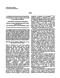
The sensor consists of four cameras used for the dense image matching and one camera with a larger field of view for the registration of multiple shots (figure 1). The four cameras for the dense image matching have a resolution of 5 Megapixels and are equipped with lenses with a focal length of 8mm. They are arranged in a square with the size of 7.5 by 7.5cm on a solid aluminum bar to provide a stable relative orientation. The fifth camera with a resolution of 2 Megapixels equipped with a lens with 4.7mm focal length is installed between the lower two matching cameras. An aluminum frame is surrounding the cameras in order to protect them from damage. Several mounts for the connection to tripods and arms for a flexible use are installed at this frame. The Microsoft Kinect is attached at the top with the pattern projector at the same height like the cameras to minimize occlusions.
The employed dense image matching method is specifically designed for close range applications. It uses a hierarchical approach to narrow down the search space for corresponding pixels in the matched image. This is not only beneficial for the resolution of matching ambiguities but also reduces computation time and memory requirements considerably. The Semi Global Matching optimization [Hirschmüller, 2008] enables the derivation of low noise point clouds for small baselines using the high similarity between the imagery. Structure and Motion reconstruction methods are used for the computation of exterior orientations without initial information. Feature points are extracted from the images and used in combination with sequential Bundle Adjustments. The
Figure 1: Sensor overview
The four matching cameras were equipped with 670nm filters in order to block parts of the visible light and make the projected pattern visible. Thus, texture is available from the object itself and the Kinect. The fifth camera with the large field of view was not equipped with this filter in order to avoid disturbances of the pattern during the feature extraction for the registration of different shots since the pattern is moved with the sensor. The cameras are transferring the imagery via USB 2.0. All images are captured at the same time. However, multiple USB controllers are required to transfer all images at once at a reasonable time. For a fast data transfer and to be able to use a laptop for the acquisition we recommend using faster interfaces such as Ethernet or USB 3.0. Furthermore, hardware triggering is important when images are not acquired from a tripod or another stabilization to ensure a synchronous exposure. 2.1 Acquisition geometry For the definition of the camera base lengths, the distance to the object and the focal length several constraints have been taken into account. The point accuracy is influenced by the acquisition geometry, defined by the intersection angle and the image scale, and the accuracy of the image matching method. The employed dense image matching method provides large completeness and low noise for imagery with similar image content. Thus, the overlap must be high which is also beneficial for the reduction of occluded areas. This is achieved by a small baseline. Thus, the base length is defined as a compromise between image similarity and intersection angle since too small angles would reduce the accuracy. The final parameters of the system are defined according to the accuracy and resolution requirements. For the stereo normal case, disparities d between two images on a base B are expected to occur along the epipolar line direction. Thus, the relation between object distance H of point P in object space and the corresponding image measurements in both images p and q can be expressed as follows [Kraus, 2007]: �� �
�� �� � � � � �
Thus, the relation between the measurement precision in image space and the point precision in object space can be approximated as: � �ଶ �ு � � � � �� ௗ The employed cameras with a resolution of 5 Megapixels have a pixel pitch of 3.45µm. The precision of the dense image matching method including the Semi Global Matching optimization is expected to amount 0.2 - 0.3 pixels depending on the image similarity [Rothermel et al., 2011]. Consequently, the working distance of 70cm leads to a reasonable compromise between precision and acquisition efficiency as described in table 1. Distance Precision Resolution Footprint
[cm] [mm] [px/mm²] [cm]
50 0.43 21.5 45*36
70 0.84 11.0 65*53
100 1.73 5.4 98*81
120 2.48 3.7 119*98
Table 1: Theoretical approximate precision in object space, resolution and footprint size for different acquisition distances.
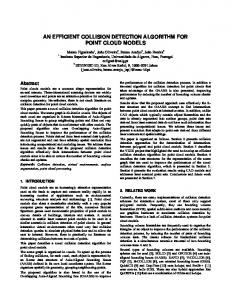
Figure 2: Image footprint at 70cm distance to the object. The coloured area represents the overlap between the four matching cameras while the outer square is the footprint of the fifth camera with the very large field of view.
The effective completeness of the dense matching method is dependent on the similarity between images and on the availability of texture. Due to the high image overlap the similarity is high which leads to a completeness between 60 to 100% within the overlapping area. Thus, almost each pixel leads to a 3D point finally. Additional density can be expected due to the overlap of point clouds from several shots. During the previous theoretical accuracy approximations the impact of the exterior orientation has been neglected. However, the quality of the exterior orientation is significantly important for the derivation of high resolution point clouds. Shifts along the epipolar direction highly correlate to the distance measurement while shifts across the epipolar direction can be compensated up to 0.5 pixels by the dense matching method. Larger shifts lead to mismatches since corresponding pixels are only searched along the epipolar direction. 2.2 Calibration In order to derive the interior orientation the sensor was calibrated using a standard method employing a pattern. The relative orientation between the cameras is derived by averaging the solution for each acquisition position. However, since the acquisition distance is very short and due to the high accuracy requirements the relative orientation is only used in laboratory conditions. For long term use the relative orientation is preferably determined by the exterior orientation method described in section 4, since the stability might not be sufficient. Reasons for that can be the slight instability of the metal frame or impacts like temperature. Also, slightly asynchronous exposure can lead to shifts which exceed the tolerance of the requirements for this high resolution application. 3. SOFTWARE PIPELINE OVERVIEW The pipeline for the derivation of 3D point clouds from the acquired imagery can be divided into the Structure and Motion reconstruction part and the subsequent dense image matching part. As shown in the flowchart (figure 3) the calibration of the camera rig is used for the rectification of the images which are used in the Structure and Motion reconstruction step for the computation of exterior orientation. The subsequent extraction of feature points and the bundle adjustment are described in section 4. The derived accurate orientations from the refining bundle adjustment are used in the dense image matching step, where stereo models within the camera rig are matched using a hierarchical approach as described in section 5. The resulting
disparity images are subsequently used within a multi baseline triangulation for the derivation of one dense point cloud for each acquisition station. Within a point cloud post-processing step several filters are applied in object space to reduce noise and outliers as described in section 6.
the efficient and reliable matching of images with large depth variations. A point triangulation step (section 5.3) for the resulting disparity images uses redundant correspondences and filtering techniques for the reduction of noise and blunders. 5.2 Dense stereo method The key challenge of dense image matching is the resolution of ambiguities, since each grey value in the image is appearing multiple times. Therefore, we employ four techniques to resolve these ambiguities: 5.2.1
Figure 3: Flowchart processing pipeline
4. EXTERIOR ORIENTATION For the derivation of accurate exterior orientations we implemented an efficient Structure and Motion reconstruction method [Abdel-Wahab et al., 2011]. It derives the exterior orientations without initial values by sequentially adding images to a bundle. Therefore, features are extracted from the imagery and matched to each other. By using an initial network analysis step large sets of unordered images can be processed efficiently without performing this step for each available image pair. The number of unknowns within the Structure and Motion process can be reduced by using the interior orientation determined in the test field calibration. Therefore, the images are rectified by removing the distortion. Furthermore, the focal length is introduced with a large weight into the bundle adjustments of the Structure and Motion process. The relative orientation between the cameras derived by the calibration of the camera rig can be used to derive a scaled point cloud for each acquisition station. Consequently, the exterior orientation of the sensor must be determined for each shot only by using the fifth camera. Beside the proposed method also point cloud registration techniques can by employed such as the Iterative Closest Point method. This is specifically beneficial if no texture is available on the object or acquisition angles are larger than 50 degrees and thus do not allow the reliable registration by features in the image only. If the accuracy of the relative orientation is not sufficient for reasons as described in section 2.2 the orientation for all cameras can be derived by the Structure and Motion reconstruction method. The scale within this procedure can be either introduced by fixing base lengths derived within the calibration or by using ground control points. Furthermore, sufficient texture on the object beside the texture projected by the Kinect must be available to enable a reliable registration of the matching cameras. 5. DENSE IMAGE MATCHING 5.1 Strategy The dense image matching method is performed on each stereo model between the four matching cameras of the rig. We developed a hierarchical dense stereo method (section 5.2) for
Epipolar images Hierarchical matching Patch matching cost Semi-Global Matching optimization Epipolar images
If high quality relative orientations between the two matched images are available the search space can be reduced to the epipolar line. For a fast processing we compute undistorted epipolar images and perform the matching only along the xdirection of the images. The resulting correspondences for each pixel is represented by the disparity which is defined as the difference between the x coordinate in the base image and the x coordinate in the match image. Thus, the matching result can be stored efficiently as a 32Bit float image. Another advantage of epipolar images is the high similarity between the images. Due to the warping on a common image plane the perspective changes across the epipolar line direction are lower and thus support the matching. 5.2.2
Hierarchical matching
Using image pyramids enables narrowing down the search space along the epipolar line direction. Matching images on a low resolution reduces the number of possible correspondences which leads to a lower number of ambiguities. Also, search ranges over the whole image are possible on low resolution which enables a matching without initial depth information. Narrowing down the search space enables the processing of imagery with strong variations in image scale resulting from large depth variations as commonly occurring for close range applications. Without a dynamic narrowing the disparity search range must be chosen very high, which not only leads to a large number of ambiguities but also requires high computational efforts. The hierarchical approach is based on performing a matching on a high pyramid level first and subsequently using the result as initial information for the next lower pyramid level until the final resolution is reached. In order to reduce the number of mismatches in this initial information several filters are applied. Most mismatched correspondences and occluded pixels are eliminated from the disparity image by validating the disparity value of each pixel using a consistency check. This check is performed by comparing the matching results for both directions: from image 1 to image 2 and the other way round. If the disparity difference between these solutions is greater than 1 pixel the correspondence is set to invalid in both resulting disparity images.
5.2.3 Additionally, a speckle filter is applied where all disparity patches with an area of less than 100 pixels are eliminated. A separate area is defined if the disparity jump to the neighboring disparities is larger than 1 pixel. This setting is useful for imagery with high similarity where the disparity variations are not too large. This is specifically the case for the proposed sensor since the base is small and thus, the Semi Global Matching optimization can be applied.
Patch matching cost
Pixel sets enable a more reliable matching in contrast to the comparison of grey values of single pixels. Ambiguities are resolved by taking into account the pixel neighborhood and thus enable the determination of disparities even for small untextured areas. Reliable matching pixel masks can be determined due to the high similarity of the images resulting from the epipolar image projection. Therefore, we employ a Census based matching cost, which is particularly robust against radiometric differences [Zabih & Woodfill, 1994; Hirschmüller, 2010]. For each pixel the information of higher and lower grey values within a mask around this pixel is stored. The matching cost is derived by comparing this information between the images pixelwise, which is highly independent of radiometric differences such as brightness or contrast since no absolute grey value differences are evaluated. On the final pyramid level and thus, after resolving most ambiguities the Mutual Information [Viola et al., 1997] matching costs can be employed which provides an even higher robustness against radiometric differences. Furthermore, it is better suited for the used estimation of sub-pixel accuracy where the costs are directly interpolated. 5.2.4
Figure 4. Cost distribution along an epipolar line. The x-axis represents the epipolar line, the y axis the disparity and the grey value the cost (grey: high, black: low, white: not evaluated). The search space and consequently the number of evaluated costs are narrowed down from pyramid level 4 (first figure) to 0 (last figure, full resolution).
The resulting cleaned disparity image is passed to the following pyramid level after scaling it up to twice the width and height and multiplying the disparities by 2. Subsequently, it can be used to determine a new search range for the matching on the current pyramid level. This search range is not determined for the whole image, but instead for each pixel individually as shown in figure 4. Therefore, all disparities within a certain mask around the destination pixel (e.g. 5x5 pixels) define the new range by their minimum and maximum value. This range is then extended by an additional buffer disparity, e.g. 1 pixel in each direction to avoid sampling issues resulting from the different image resolutions and to ensure that the search range does not become 1 pixel for planes parallel to the image sensor. Within the reduced search range a matching cost is determined for each possible disparity as described in paragraph Patch matching cost. The minimum cost represents the final disparity. Sub-pixel accuracy is interpolated by estimating a quadratic curve through the minimum cost and the two neighboring costs. The new disparity solution for each pixel is used as initial information for the next pyramid level until the original resolution is reached as shown in figure 3.
Semi Global Matching
The Semi Global Matching method [Hirschmüller, 2008] represents a global optimization for stereo matching. The introduction of a global smoothness constraint into the cost function leads to a smoother disparity image and consequently to noise reduction in the resulting point clouds. Also, the sensitivity against image noise is reduced while small untextured areas can be compensated. By approximating this smoothness constraint by linear paths through the image the Semi Global Matching method enables efficient implementations in contrast to other global optimization approaches. The smoothness constraint uses the high similarity between the images by enforcing similar disparities in neighboring pixels. This is especially beneficial for matching on small baselines like in this application, where the similarity between the imagery is high but the ray intersection angle very small. The implementation of the original Semi Global Matching method has relatively high memory consumption, since cost values must be stored and aggregated for all pixels and subsequently all possible disparities within a certain range. Thus, the number of evaluated elements is given by ∗ � ∗ , where ∗ � is the image size and the number of examined disparities within this fixed range. This fixed disparity range is low if the relation between the observed surface undulation and the image scale is low, as occurring for images taken from a far distance to the object such as nadir aerial imagery. In contrast, the amount of disparities to be evaluated is very high for high resolution images of scenes with large depth variations. In order to reduce the resulting high amount of required memory and computation time, we modified the Semi Global Matching method for close range applications by adapting it to the dynamic cost storage and evaluation described in the paragraph Hierarchical matching where the disparity range is narrowed down for each pixel individually.
However, the Semi Global Matching method is only well suited for smaller intersection angles or images with low sampling on the ground. Since the smoothness constraint tries to enforce the same disparity or a disparity jump of 1pixel it works only well for surface planes parallel to the image plane or planes tilted exactly in a direction of one of the paths used during the cost aggregation step. For convergent images or large base-to-height ratio the optimization fails if the ground sampling is high and thus disparity jumps larger than 1pixel occur at the surfaces to be reconstructed. However, since the acquisition geometry of the proposed sensor system is adjusted to the properties of the Semi Global Matching method the similarity between the images and consequently the performance of the optimization is high. The small baselines and a specific working range of 50cm to 120cm ensure a suited image scale in combination with the base-toheight ratio. Thus, noise resulting from the low base-height ratio is reduced significantly while depth details are preserved by using a low smoothness constraint.
6. POINT CLOUD POST-PROCESSING After deriving the point clouds for each acquisition station a point cloud post-processing is performed. Even though multiple filters have been applied in image space and during the triangulation step a few outliers may remain. In order to filter these and reduce the noise additionally, filters in object space are applied. We implemented these filters by using available functions from the PCL Library [Rusu et. al., 2011, PCL, 2011], an open source library for point cloud processing published under the BSD license. Especially the available statistical outlier removal filter and the radius outlier removal filter are suitable for the task of cleaning up the point clouds. 7. EXAMPLE OF USE 7.1 The Amsterdam project
5.3 Multi-stereo point triangulation In order to derive a 3D point cloud from the disparity images derived during the dense matching a multi-stereo point triangulation step is performed. Each disparity image stores the correspondence information for each pixel to a pixel in the match image of the stereo model. If multiple images are matched to one base image also multiple of these disparity images are available. Within our multi-stereo approach a point cloud is derived for each of these base images. If a pixel in the base image has one or more corresponding measurements represented by a valid match stored in a disparity image it can be triangulated to object space by using the exterior orientation to intersect the resulting rays of view. Therefore, an efficient linear triangulation method is employed [Hartley et al., 2008].
Figure 6: East tympanum at the palace from distance and detail. The statues are larger than natural size; the size of the targets is 4 by 3cm.
During a cultural heritage data recording project images were acquired for two tympana at the royal palace of Amsterdam. Each of the tympana covers a triangular shaped area of about 25m in width by 5m in height containing a relief with complex surface geometries such as statues. A first comprehensive report about the project is given by D. Fritsch et al., 2011. In order to derive a point cloud with a sampling of 1mm on the object and sub-mm accuracy the presented sensor was employed for the data recording on scaffolding. Within 9.5 days about 2,000 stations were acquired leading to a total amount of about 10,000 images.
Figure 5: Pixelwise 3D point triangulation. Each image is matched to the base image (red). The resulting correspondences are intersected in images space to derive a point for each matched pixel in the base image.
In the case of the proposed sensor system one base camera is selected, e.g. the upper left matching camera. The images from the other matching cameras are now matched to this base image using the dense stereo method. Thus, up to 3 stereo models can be matched by using this method. The high redundancy increases the accuracy and can be used to filter the points, e.g. by introducing a constraint that each point must be observed in at least 3 images. Thus, blunders can be eliminated efficiently.
Figure 7: The sensor during the data acquisition. On the left mounted on a stand; on the right stabilized by an arm.
For the complete coverage the images ware acquired in a meandering pattern within each of the three levels of scaffolding firstly. After finishing this acquisition in nadir direction also convergent shots have been captured to complete surfaces which were occluded or not covered. Ground control points measured by tachymetry provided the transformation to the global coordinate system. About 2 billion 3D points were computed for both tympana. However, the potential point density for this dataset is expected to be about four times higher.
texture as well. However, if object space methods for the registration are used point clouds can be recorded without texture on the object. Within our current work we investigate the impact of different illumination and texture projections in the context of a comprehensive accuracy assessment. Future improvements for the data acquisition and processing could be achieved by investigating on the use of guided acquisition. The Structure and Motion techniques could be extended to Simultaneous Location and Mapping (SLAM) methods by using an image stream instead of single shots. This can be used to support the data recording in order to ensure an efficient and complete recording with optimal acquisition geometry. 9. ACKNOWLEDGEMENTS We would like to thank Thomas Zwölfer and Patrick Tutzauer for their support during the project in Amsterdam. Also, we would like to thank Erwin Christofori, Jörg Bierwagen and the team from the surveying company Christofori und Partner for the pleasant cooperation during this project. 10. REFERENCES Abdel-Wahab, M., Wenzel, K., Fritsch D. 2011. Reconstruction of Orientation and Geometry from Large Unordered Image Datasets for Low Cost Applications. Low-Cost 3D (LC3D) workshop, December 2011 Fritsch, D., Khosravani, A., Cefalu, A., Wenzel, K, 2011. MultiSensors and Multiray Reconstruction for Digital Preservation. In: Photogrammetric Week ’11 (Ed. D. Fritsch), Wichmann, pp. 305-324. Hartley, R., Zisserman, A., 2008. Multiple View Geometry in Computer Vision. Cambridge University Press, 2nd edition, 6th printing edition. Hirschmüller, H., 2008. Stereo Processing by Semi-Global Matching and Mutual Information. IEEE Transactions on Pattern Analysis and Machine Intelligence, 30(2), pp. 328–341. Hirschmüller, H., Bucher, T., 2010. Evaluation of Digital Surface Models by Semi-Global Matching. DGPFKameraevaluierungsprojekt: 3-Ländertagung. Wien, July 2010
Figure 8: Point cloud for the west tympanum with about 1.1 billion points and a detail. Third image: detail from the east tympanum.
Kraus, K., 2007. Photogrammetry, Geometry from Images and Laser Scans. de Gruyter, Berlin, 2nd edition edition. 61
8. CONCLUSIONS AND OUTLOOK PCL, 2011. Point Cloud Library. URL: www.pointclouds.org The proposed sensor system is designed for the recording of very dense point clouds with high accuracy requirements. It is specifically suited for large scale applications where recording efficiency and flexibility are required. The point cloud derivation for each single shot enables a fast acquisition while the compact size is beneficial for the recording of complex surfaces. Furthermore, slow movements of the sensor can be compensated if a sufficiently short exposure time is chosen. Due to the artificial texture projected by the Microsoft Kinect surface information can also be derived for low textured areas. However, for high accuracy requirements slight texture should be provided by the object since the Kinect pattern is not continuously but has small gaps. Furthermore, the implemented determination of the exterior orientation for the registration of multiple shots is based on feature points and thus, requires
Rothermel M., Haala, N., 2011. Potential of Dense Matching for the Generation of High Quality Digital Elevation Models. In ISPRS Proceedings XXXVII 4-W19 Rusu, R. B., Cousins, S., 2011. 3D is here: Point Cloud Library (PCL). International Conference on Robotics and Automation, Shanghai 2011 Viola, P., Wells, W. M. 1997. Alignment by Maximization of Mutual Information. International Journal of Computer Vision, 24(2), 137–154. Zabih, R., Woodfill, J., 1994. Non-parametric Local Transforms for Computing Visual Correspondence. Third European Conference on Computer Vision. Stockholm, Sweden.