Keywords: Virtual Network, Management of Networks and Services, VPN .... 3. The service provider reserves the calculated amount of needed resource by.
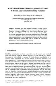
A Multi-Commodity Flow Based Approach to Virtual Network Resource Allocation W. Szeto, Y. Iraqi and R. Boutaba School of Computer Science University of Waterloo 200 University Avenue West Waterloo, Ontario, Canada, N2L 3G1 {wwszeto, iraqi, rboutaba}@bbcr.uwaterloo.ca
Abstract
The Virtual Network (VN) concept has been studied as a useful mean in supporting rapid service creation and deployment. In this research paper, we propose a scheme for allocating resource to VNs with the objective of maximizing the number of VNs that can be accommodated into the network. In our scheme, a set of resource is pre-allocated for each pair of edge nodes, according to the solution of the multi-commodity flow problem. A VN creation request consists of a set of edge nodes and the bandwidth requirement between each edge node pair. A VN creation request is satisfied by exercising the associated pre-allocated resource and the residual network resource. Simulation results show that our scheme offers better performance over traditional methods, in terms of request blocking ratio and network resource utilization.
Keywords: Virtual Network, Management of Networks and Services, VPN
1 Introduction In recent years, much research effort has been invested in the dynamic creation, deployment and management of novel network services [8]. These services range from low-level bearer services such as bit forwarding to high-level value-added services such as video conferencing. The virtual network concept has been proposed as a useful mean in supporting rapid service creation through abstraction and virtualization of network resources [1, 3, 15, 16]. A Virtual Network (VN) is a service concept that considers a collection of remote entities as if they are all part of a single network. Many applications have been identified that can benefit from the VN concept [12]. A network service providers’ ability to provision virtual networks (VNs) efficiently and quickly offers competitive advantage over other providers. In this paper, we proposed a method for efficient VN resource allocation with the goal of maximizing the number of VNs provisioned. Our scheme is based on the solution to the classical network flow problem, the multi-commodity flow problem. In the next section, we discuss the virtual network concept in a generic manner and describe a management framework based on it. In section 3, we present our solution to the VN capacity allocation problem. Section 4 analyzes and compares the performance of our approach against others. In section 5, we review similar work in the open literature. Section 6 summarizes the contributions of this paper along with some remarks for potential future work.
2 Resource Management Using the Virtual Network Concept In this section, we discuss the virtual network concept and describe a network resource management architecture based on this concept. The notion of virtual network has been studied for the past few years primarily in the context of virtual private networking (VPN) services that offer secure communication to a closed group of users. At the same time, the virtual network concept has been exploited as a mean to simplify the tasks and mechanisms for network control and management [1, 3, 15, 16]. The Virtual Network Resource Management System (VNRMS) was proposed to provide flexible and customizable control over virtual network resources [1]. VNRMS is intended to provide a programmable networking environment, where multiple levels of virtual networks can be generated out of a single physical network for various management purposes. In the context of the VNRMS framework, a Physical Network (PN) is being considered as a collection of Physical Network Resources (PNRs) that include transmission and switching resources. Similarly, a Virtual Network (VN) is being viewed as a collection of Virtual Network Resources (VNRs), where a VNR is a logical subset of a PNR.
2
Hence, a VN can be viewed as an abstracted partition of a PN. In order to allow logical operations on network resources, PNRs in the physical domain are projected onto the virtual domain through a process called the abstraction of network resources. The abstraction process is illustrated horizontally in Figure 1, where the PN from the physical domain is abstracted as a root-VN in the virtual domain. The same figure also illustrates, vertically, the PN and VNs being viewed as a collection of physical and virtual network resources, respectively. Once the root-VN is established, multiple child VNs can be generated from it through an operation called spawning. VN spawning involves determining which VNRs should be part of the new VN and how much resource should be assigned to it. New VNs can be spawned out of old VNs, thus creating hierarchical layers of VNs.
Figure 1: Relationship between PN and VN.
The VNRMS framework supports customer-based control of virtual network resources at different levels. At the resource level, a resource agent controls access to and performs resource partitioning for a single VNR. At the network level, a VNRMS manages and configures a collection of VNRs that forms a VN. With the appropriate communication interfaces, a VN can be associated with a customer-based control system, which allows the customer to exercise its own control algorithms and mechanisms onto the VN. Figure 2 illustrates the interactions between resource agents, the provider-based control system (Provider VNRMS) and customer-based control systems (CNRMS). The provider VNRMS have full control and access to all the resource agents in the network; while each CNRMS only interacts with the resource agents that are part of its VN. The same figure also shows that the CNRMS only have access to a partition of a VNR, as indicated by a small box inside the resource agents. Note that since a VN customer could also be a network service provider for other customers, therefore the CNRMS could be the same as the provider VNRMS, plus some extra customer-specific functions.
3
Figure 2: Interaction between resource agents and VNRMS.
A resource agent is an active entity that performs resource partitioning on the associated VNR. The resource partitioning is supported by the Miblet concept. Miblets are logical structures that provide abstractive and selective views of the physical network resources allocated to VN customers [2]. The Miblet concept is derived from Management Information Base (MIB), which defines the set of configuration, statistical and status information accessible from a network element. By manipulating values defined by the MIB, we can effectively monitor and control resources inside a network element. Similarly, by manipulating values defined by a Miblet, we can control a subset of resources available in a network element. Ultimately, Miblets are disjointed subsets of a MIB, as illustrated in Figure 3 below. The figure shows that a VNR is being used by three distinct VNs and a corresponding Miblet has been created for each VN.
Figure 3: Miblets are disjointed subsets of a MIB.
In VNRMS, the VN spawning function is triggered by the arrival of a customer VN request. The VN spawning process composes of determining the set of VNRs that will be part of the VN and how much resource should be allocated to the VN. The procedures for establishing a VN can be summarized in the following steps: 1. A customer requests a VN with some specific resource requirements to be established from the service provider. 4
2. The service provider determines the set of network nodes and amount of resource needed in order to satisfy the request (This will be the subject matter for section 3). 3. The service provider reserves the calculated amount of needed resource by creating a Miblet on each involving node, and returns the corresponding resource allocation specification to the customer. Access to Miblets is through standard SNMP commands.
3 Resource Allocation: An Approach Based On MultiCommodity Flow In this section, we present a method for determining the set of network nodes to be involved in a VN and the amount of resource to be allocated to this VN in order to satisfy a VN creation request. Our method is based on the solution to the classical multicommodity flow problem. We will first state the capacity allocation problem in a formal and abstract manner. Then we will give an example scenario where the usual method fails. Finally we will review the multi-commodity problem and present a resource allocation method based on it. We will discuss our method in the context of VNRMS. However our approach is applicable to any resource management framework that allows hard resource reservation.
3.1 Problem Definition & Assumptions The VN capacity allocation problem can be thought of as an optimization problem in capacitated graphs. We are given a directed graph, G = (V, E), representing the underlying physical network, where V is the set of network nodes and E is the set of network links. A subset of network nodes, D, are referred to as the edge or access nodes; and the set V-D are the core or transit nodes. The core nodes are solely responsible for forwarding packets, while the edge nodes also act as traffic source and sink, in addition to carrying traffic. Each undirected network link is represented by two directed arcs, one to each direction, on the graph G. A request from the customer to spawn a VN consists of two required pieces of information: the set of edge nodes to be part of the VN and a demand matrix that specifies the amount of traffic to be transmitted between each pair of endpoints. A sample demand matrix is shown in Table 1, which states that 5 units of traffic are expected between each pair of VN edge nodes {A, E, H}. A request is satisfied by reserving the needed amount of bandwidth and a request is rejected if the amount of available resource is insufficient. The primary objective of the capacity allocation problem is to maximize the number of satisfied requests. Furthermore, we assume that a request can not be partially fulfilled and that the size of each request (i.e. aggregated sum of bandwidth demand between all endpoint pairs) is small relative to the physical network capacity.
5
From
To A E A - 5 E 5 H 5 5
H 5 5 -
Table 1: A sample demand matrix.
3.2 Example Scenario One logical way to setup a VN, called the flat model [12], is to establish a set end-to-end tunnels, one for each pair of endpoints. Thus a VN can be viewed as a set of paths with reserved resource, each path connecting a pair of VN edge node. The problem of spawning a VN is equivalent to searching for a feasible set of paths with sufficient residual bandwidth according to the customer request. One approach to this problem is to use existing constraint-based routing algorithms to compute the set of paths. However such approach does not work well because each path is computed individually without taking into account additionally available information. Consider a situation where the current network state is represented by the graph in Figure 4. The capacity of each link is indicated in the figure and the set of edge nodes are {A, E, H}. Suppose a request arrives with a demand matrix given in Table 1. Assume that the shortest-path algorithm (based on number of hops) is employed to compute a path for each pair of edge nodes starting with {A, E}, then {A, H} and so on, as shown in Table 2. The process fails at the 4th iteration because there is insufficient residual bandwidth, and the request is therefore rejected. However it is possible to accommodate this request onto the network and we will show how in the next section.
A
B
C
D
E
Core Node Edge Node
F
G
H
8 Units 10 Units
Figure 4: A network scenario where using individual path computation fails.
Iteration # 1 2 3
Edge Pair {A, E} {A, H} {E, A}
Path A_F_G_D_E A_F_B_C_D_G_H E_D_G_F_A
6
4
{E, H}
Fails!
Table 2: Paths computed.
3.3 VN Resource Allocation Based On Multi-Commodity Flow The simple example above shows that the first approach fails to accept a request even though there is sufficient resource available to support this request. This is the motivation behind to coming with a better solution. Our approach pre-allocates resource for each commodity based on the solution of the multi-commodity flow problem and then performs least-cost routing on the pre-allocated resource plus the residual resource in the network. In the multi-commodity flow (MCF) problem, each commodity (si ti, di) is composed of a source node si, a destination node ti and a demand di. The objective of this problem is to minimize the cost of routing a set of commodities simultaneously in the network, subjected to capacity constraints. One variation of the MCF problem is the maximum-concurrent flow problem (also known as the demand commodity flow problem [5]). In this problem, the objective is to maximize the scaling factor f, such that for each commodity i, f * di amount of demand can be routed simultaneously. Using linear programming, both problems can be solved in polynomial time [6]. The solution to the maximum-concurrent flow problem, if one exists, gives the value of the scaling factor f and the flow placement of each commodity on the network. The commodity placement tells us the exact amount of each commodity that should be placed on each arc in order to achieve the optimal f value. The idea behind our VN capacity allocation scheme is to view each network edge pair as a commodity and initialize each commodity with unit demand. The next step is to solve the corresponding maximum-concurrent flow problem, and the solution gives the largest demand for each commodity subjected to network capacity. Then based on the solution, pre-allocate network resource for each commodity according to the flow placement. If there are 5 edge nodes in network, then there are 20 edge pairs (i.e. 20 commodities). For each specified end point pairs in a VN creation request, only the pre-allocated resource for that pair will be used for path establishment. If the pre-allocated capacity does have sufficient resource to satisfy a request, our scheme will switch to least-cost routing on the remaining pre-allocated resource plus the residual resource. In least-cost routing, the cost of a link is equal to one over the residual link bandwidth. This last step ensures maximum resource utilization. We will go through the example scenario from Figure 4 using our VN resource allocation method and show that it will not suffer from the same problem as in the previous approach. First, consider each network edge pair as a commodity and initialize each commodity with unit demand. There are six commodities in total. By solving the corresponding maximum-concurrent flow problem, we obtain the optimal value for f to be 5 and the flow placement as shown in Table 3. For each commodity, 5 units of bandwidth will be reserved along the path according its placement. When a request with
7
demand matrix of Table 1 arrives, it can be satisfied by routing over the pre-allocated paths. Commodity (A, E, 5) (A, H, 5) (E, A, 5) (E, H, 5) (H, A, 5) (H, E, 5)
Placement A_B_C_D_E A_F_G_H E_D_C_B_A E_G_H H_G_F_A H_G_D_E
Reserved Bandwidth for Placement 5 5 5 5 5 5
Table 3: Solution to the maximum-concurrent flow problem.
Note that in the above example, a unit demand is initially assigned to each commodity. The initial demand can be set differently if knowledge such as the expected amount of demand between each pair of edge nodes is known in advance. Such information could be inferred from traffic trace or geographical location of customers. For example, if there are twice the numbers of customer using edge node A as the access point than other edge nodes, then we would normally expect the demand to and from node A to be twice as much as other edge nodes. Accordingly the initial demand for any edge pair with A in it can be set to 2 while the demand for all other edge pairs remains 1.
4 Performance Evaluation The first part of this section describes the simulation scenarios employed in evaluating our method for VN resource allocation. The second part of this section discusses and analyzes the result of our evaluation.
4.1 Simulation Design We compare our method for capacity allocation against two other approaches that employ point-to-point routing schemes. The first approach, called SPF-CA, uses shortest-path routing with respect to number of hops and the second one, named LCP-CA, uses leastcost routing, where the cost of a link is set to be the reciprocal of the residual (unreserved) bandwidth of that link. Two performance metrics of interest are the bandwidth blocking ratio and the network utilization. The bandwidth blocking ratio (BWBR) is equal to the total amount of rejected bandwidth over the total amount of requested bandwidth. The requested bandwidth of a VN creation request is the aggregated bandwidth requirement between all pairs of nodes in that VN request. The lower the BWBR, the higher the number of VNs established in the network. The network utilization is equal to the total amount of reserved bandwidth over the total network capacity. Four different sets of experiments are executed and they are based on a 8
combination two factors, static or dynamic VN setup and uniform or non-uniform demand. Static VN represents long-lived VNs while dynamic VN emulates short-lived VNs. Uniform demand implies all edge pairs have an equal probability of being included in a VN request. In the case of non-uniform demand, some edge pairs have a higher probability of being chosen to be part of a VN. Table 4 summaries the four different sets of experiments.
Uniform Demand Non-uniform Demand
Static VN Setup Experiment#1 Experiment#3
Dynamic VN Setup Experiment#2 Experiment#4
Table 4: Four sets of experiments.
In experiment 2 and 4, dynamic VN creation request arrives based on a Poisson distribution with mean equal to 100 time units and the VN holding time is based an Exponential distribution with mean equal to 20000 time units. Two network topologies, 1 and 2, are chosen for use in the experiments and they are taken from the backbone networks of two different ISPs, respectively [17, 18]. In each topology, a set of nodes are designated as edge routers and topology 1 and 2 contains 4 and 9 edge nodes respectively, as shown in Figure 5. Each VN creation request contains a set of involving edge nodes and the required bandwidth between each pair. The number of included edge nodes and the bandwidth requirement between each pair, are random variables that takes on values from {2, 3} and {2, 3, 4} respectively. Each set of experiment is run five times and the results shown in the next section are the average of five trials. The simulations are carried out using an in-house developed discrete event simulator implemented in Java. PPRN, a popular multi-commodity flow problem solver, is incorporate in our implementation [14].
Figure 5: Topology#2 is on the left and topology#1 is on the right (source [17, 10]).
9
4.2 Analysis of Simulation Results For the first type of experiment, 20000 static VN setup requests are sent to topology 1 and 2 and results for the first 10000 bandwidth requested are depicted in Figure 6 and Figure 7. In both cases, our scheme (MCF-CA) for VN capacity allocation has a significantly lower blocking ratio than the other two schemes. All curves in both diagrams approach the maximum blocking ratio of 1 as expected, since the established VNs stay in the network for the duration of the experiment. We define the saturation point in the simulation as the point where 99% of subsequent requests arrive to the network are rejected due to insufficient residual resource. Clearly the saturation point is different for different schemes. For example, the saturation point for SPF-CA in topology 1 occurs when requested BW equals 2747, while the saturation point for LCPCA in the same topology does not occur until requested BW equals 4366. The total amount of accepted bandwidth for the three schemes at the saturation point is shown in Table 5. We have calculated the improvement of MCF-CA over the other two schemes in Table 6. In Table 7 indicates that our scheme results in higher network utilization than the two other schemes.
Blocking Ratio
Exp1,Top1: Blocking Ratio VS Requested BW 1 0.9 0.8 0.7 0.6 0.5 0.4 0.3 0.2 0.1 0
SPF-CA LCP-CA MCF-CA
0
2000
4000
6000
8000
10000
Requested BW
Figure 6: Partial result for Experiment 1 Topology 1.
10
Blocking Ratio
Exp1, Top2: Blocking Ratio VS Requested BW 1 0.9 0.8 0.7 0.6 0.5 0.4 0.3 0.2 0.1 0
SPF-CA LCP-CA MCF-CA
0
2000
4000
6000
8000
10000
Requested BW
Figure 7: Partial result for Experiment 1 on topology 2.
Topology1 Topology2
SPF-CA LCP-CA MCF-CA 1228 1419 1467 790 837 856
Table 5: The total amount of accepted bandwidth at the saturation point for Experiment 1.
Topology1 Topology2
SPF-CA LCP-CA 19.5% 3.4% 7.6% 2.3%
Table 6: Improvement of MCF-CA over the other two schemes in terms of bandwidth accepted at the saturation point in Experiment 1.
Topology1 Topology2
SPF-CA LCP-CA MCF-CA 58.38% 60.92% 61.21% 27.23% 28.16% 30.37%
Table 7: Network bandwidth utilization measured at the end of simulation for Experiment 1.
In the second experiment, 20000 dynamic VN setup requests sent to the two topologies and simulation results are shown in Figure 8 and Figure 9. Unlike the previous experiment, the curves in this experiment stabilize as a horizontal line after long period of simulation time. In both cases, our scheme offers a significant improvement over the other two schemes under consideration, as shown in Table 8 and Table 9. Table 10 shows that our scheme our scheme offers better bandwidth utilization than the other two methods.
11
Exp2,Top1: Blocking Ratio VS Requested BW 0.3
Blocking Ratio
0.25 0.2
SPF-CA
0.15
LCP-CA MCF-CA
0.1 0.05 0 0
20000
40000
60000
80000 100000 120000 140000
Requested BW
Figure 8: Experiment 2 result on topology 1.
Exp2,Top2: Blocking Ratio VS Requested BW 0.6
Blocking Ratio
0.5 0.4
SPF-CA
0.3
LCP-CA MCF-CA
0.2 0.1 0 0
20000
40000
60000
80000
100000
120000
140000
Re que s te d BW
Figure 9: Experiment 2 result on topology 2.
Topology1 Topology2
SPF-CA LCP-CA 0.241 0.228 0.529 0.509
MCF-CA 0.191 0.489
Table 8: Blocking ratio measured at the end of the simulation for Experiment 2.
Topology1 Topology2
SPF-CA LCP-CA 6.9% 4.8% 8.5% 4.1%
Table 9: Improvement of MCF-CA over the other two schemes in terms of bandwidth acceptance ratio in Experiment 2.
12
Topology1 Topology2
SPF-CA LCP-CA 41.0% 46.9% 19.7% 21.5%
MCF-CA 53.4% 24.8%
Table 10: Average network bandwidth utilization for Experiment 2.
In experiment 3 and 4, one of the edge nodes in each topology is randomly chosen to have twice as many customers behind it as the other edge nodes. Any edge pair with this edge node will therefore have twice the probability of being chosen in a VN request as the other edge pairs. Experiment 3 and 4 uses the same parameters as experiment 1 and 2 respectively. Figure 10 and Figure 11 shows the partial simulation result for experiment 3 while Figure 12 and Figure 13 show the result for experiment 4. In terms of MCFCA’s performance gain over the other two schemes, Table 12 and Table 15 show that the gain is higher in most non-uniform demand experiments than in uniform demand experiments. Compare to the result for experiment 1 and 2, the blocking ratio for experiment 3 and 4 tends to be higher here as expected. In all cases, our scheme accepts more VNs to be established in the network than the other two approaches. Exp3, Top1: Blocking Ratio VS Requested BW 1
Blocking Ratio
0.8 SPF-CA
0.6
LCP-CA 0.4
MCF-CA
0.2 0 0
2000
4000
6000
8000
10000
Requested BW
Figure 10: Partial result for experiment 3 on topology 1.
13
Exp3, Top2: Blocking Ratio VS Requested BW 1
Blocking Ratio
0.8 SPF-CA
0.6
LCP-CA 0.4
MCF-CA
0.2 0 0
2000
4000
6000
8000
10000
Requested BW
Figure 11: Partial result for experiment 3 on topology 2.
Topology1 Topology2
SPF-CA LCP-CA 1161 1164 659 715
MCF-CA 1271 796
Table 11: The total amount of accepted bandwidth at the saturation point for Experiment 3.
Topology1 Topology2
SPF-CA LCP-CA 9.4% 9.2% 20.8% 11.3%
Table 12: Improvement of MCF-CA over the other two schemes in terms of bandwidth accepted at the saturation point in Experiment 3.
Topology1 Topology2
SPF-CA LCP-CA 59.5% 60.5% 28.1% 30.6%
MCF-CA 63.1% 31.5%
Table 13: Network bandwidth utilization measured at the end of simulation for Experiment 3.
14
Blocking Ratio VS Requested BW 0.3
Blocking Ratio
0.25 0.2 SPF-CA LCP-CA
0.15
MCF-CA 0.1 0.05 0 0
20000
40000
60000
80000
100000
120000
140000
Re que s te d BW
Figure 12: Result for experiment 4 on topology 1.
Blocking Ratio VS Requested BW 0.7
Blocking Ratio
0.6 0.5 SPF-CA
0.4
LCP-CA 0.3
MCF-CA
0.2 0.1 0 0
20000
40000
60000
80000
100000
120000
140000
Re que s te d BW
Figure 13: Result for experiment 4 on topology 2.
Topology1 Topology2
SPF-CA LCP-CA 0.273 0.271 0.625 0.560
MCF-CA 0.243 0.533
Table 14: Blocking ratio measured at the end of the simulation for Experiment 4.
Topology1 Topology2
SPF-CA LCP-CA 6.8% 5.4% 24.5% 6.1%
15
Table 15: Improvement of MCF-CA over the other two schemes in terms of bandwidth acceptance ratio in Experiment 4.
Topology1 Topology2
SPF-CA LCP-CA 38.0% 42.5% 15.2% 19.1%
MCF-CA 49.1% 22.0%
Table 16: Average network bandwidth utilization for Experiment 4.
5 Related Works Work related to the VN capacity allocation problem has been investigated in various research domains such as in the area of network resource management [7, 13] and optical networking [9]. This section describes such research efforts in the open literature. The authors in [7] proposed an architecture, called VServ, for provisioning on-demand, resource-assured virtual private networking service. This prototype is executed on the service provider side, and it enables automated creation of VNs according to customer submitted requests. The customer is provided with a resource allocation specification, which entails how much resources have been reserved, if the VN topology search process is successful. The work on VServ assumes that most VPN topologies resemble tree-like shapes due to multicast applications. A large and growing number of VPN applications necessitate multipoint-to-multipoint communication, rather than point-to-multipoint or multipoint-to-point communication. In these applications, the topology of the VPN may never resemble the form of a tree or any identifiable format. In fact, restricting the topology shape inhibits the ability of seeking the optimal solution. Our approach for virtual network resource allocation does not make any assumption about the form of the topology. Our method attempts to find a feasible resource allocation in the general case. The resource allocation problem in the design of VPNs is considered in [13]. The proposed framework allocates bandwidth on each link to the VPNs with the objective of maximizing the aggregated carried bandwidth (called revenue) for all VPNs. The central part of the framework is to state the considered problem as a linear programming formulation with the goal of maximizing revenue. The allocation method is not online, meaning that it requires the knowledge of all VPNs their associated bandwidth requirements in advance. In contrast, our approach is aimed for online use and it does not make any assumption about the nature of future VN creation requests. The logical topology design problem in optical networking domain has been well studied in the past decade [9]. Typically, a logical topology is constructed to provide highcapacity and low-delay lightpaths between nodes. Ideally, one lightpath is formed between each pair of network nodes to realize the large capacity gain, but there is a fixed limit on the number of lighpaths that can exist on the same network. Therefore, deciding which pairs of nodes to form a lightpath for is central to the logical topology design
16
problem. This problem is similar to the capacity allocation problem but with a few subtle differences. In the former case, a single logical topology is constructed, while in the latter case, many virtual topologies are produced. This difference leads to distinct objective functions: the former case has the goal of load balancing traffic distribution and the latter case attempts to accommodate as many VN request as possible.
6 Conclusion and Future Work The virtual network concept has been considered as a useful mean in supporting the creation, deployment and management of new network services. Various virtual network resource management frameworks have been proposed and studied in the past few years. The VNRMS provides customizable control and management of virtual network resource, realized by the notion of Miblets. In this paper, we have presented a method for VN capacity allocation, based on the solution to the classical multi-commodity flow problem. We evaluated our approach in one small and one medium-sized ISP networks with static and dynamic VN setup requests. Our approach makes more efficient use of network resource than other traditional approaches by permitting significantly more VNs to be established. There are several research projects addressing a similar problem to ours, but their approaches have more restrictive assumptions about the customers than ours. One possible future addition to our VN capacity allocation scheme is a mechanism to detect changes in request pattern and adjust resource allocation accordingly. Currently, the decision on resource pre-allocation is made once unless the network topology changes. Over long periods of time, customers subscribing to and unsubscribing from different services may lead to changes in request pattern and traffic trend. Thus an intelligent reallocation feature is desired to deal with this issue.
7 References [1]
[2]
[3] [4]
D. S. Jun and A. Leon-Garcia. “A Virtual Network Approach to Network Resources Management.” In Proceedings of Canadian Conference on Broadband Research (CCBR'98), 1998. W.F. Ng, D. S. Jun, H. K. Chow, R. Boutaba and A. Leon-Garcia. “MIBlets: A Practical Approach to Virtual Network Management.” In Proceedings of Integrated Network Management (IM'99), 1999. J. E. Van der Merwe and I. M. Leslie. “Switchlets and Dynamic Virtual ATM Networks.” In Proceedings of Integrated Network Management (IM’97), 1997. M. C. Chan, A. A. Lazar and R. Stadler. “Customer Management and Control of Broadband VPN Services.” In Proceedings of Integrated Network Management (IM’97), 1997. 17
[5] [6]
[7]
[8]
[9] [10] [11]
[12]
[13]
[14]
[15]
[16]
[17]
V. V. Vazirani. Approximation Algorithms. Springer Verlag, Berlin, 2001. Y. Aumann and Y. Rabani. “An O(log k) Approximate min-cut max-flow theorem and approximation algorithm.” In SIAM Journal on Computing, Vol. 27, No. 1, 1998. R. Isaac and I. Leslie. “Support for Resource-Assured and Dynamic Virtual Private Networks.” IEEE Journal on Selected Areas in Communication, March 2001. A. T. Campbell, H. G. De Meer, M. E. Kounavis, K. Miki, J. Vicente and D. A. Villela. “A Survey of Programmable Networks." ACM Computer Communications Review, Vol. 29, No. 2, April 1999. K. M. Sivalingam and S. Subramaniam. “Optical WDM Networks Principles and Practice." pp79-102. Kluwer Academic Publishers 2000. M. Kodialam, and T.V. Lakshman, “Minimum Interference Routing with Applications to MPLS Traffic Engineering,” In Proceedings of Infocom 2000. A. Feldmann, A. Greenberg, C. Lund, N. Reingold, J.Rexford, and F. True. Deriving traffic demands for operational (IP) networks: methodology and experience. In ACM SIGCOMM, pages 257-270, 2000. M. El-Darieby, J. Rolia and D.C. Petriu. “Performance Modeling for Virtual Network-based Service Provisioning.” In Proceedings of Integrated Network Management (IM'01), 2001. D. Mitra, J. A. Morrison, and K. G. Ramakrishnan. “Virtual Private Networks: Joint Resource Allocation And Routing Design.” In Proceedings of INFOCOM’99, 1999. J. Castro and N. Nabona. “An implementation of linear and nonlinear multicommodity network flows.” European Journal of Operational Research, 1996. Prashant Chandra, Yang-Hua Chu, Allan Fisher, Jun Gao, Corey Kosak, T.S. Eugene Ng, Peter Steenkiste, Eduardo Takahashi, and Hui Zhang. “Darwin: Customizable Resource Management for Value-Added Network Services.” IEEE Network, Vol. 15, No. 1, January 2001. M. E. Kounavis, A. T. Campbell, S. Chou, F. Modoux, J. Vicente, and H. Zhang. “The Genesis Kernel: A Programming System for Spawning Network Architectures.” IEEE Journal on Selected Areas in Communications, Special Issue on Active and Programmable Networks, Vol. 19, No. 3, March, 2001. E. J. Anderson, “A Multicommodity Flow Based Approach to Adaptive Internet Routing,” Ph. D Thesis, Department of Computer Science, University of Washington, 2002.
18