the Poisson equation subject to separating solid boundary conditions in an Eulerian liquid simulation's pressure ... c The Eurographics Association 2011.
Eurographics/ ACM SIGGRAPH Symposium on Computer Animation (2011) A. Bargteil and M. van de Panne (Editors)
A Multigrid Fluid Pressure Solver Handling Separating Solid Boundary Conditions Nuttapong Chentanez and Matthias Müller NVIDIA PhysX Research
Abstract We present a multigrid method for solving the linear complementarity problem (LCP) resulting from discretizing the Poisson equation subject to separating solid boundary conditions in an Eulerian liquid simulation’s pressure projection step. The method requires only a few small changes to a multigrid solver for linear systems. Our generalized solver is fast enough to handle 3D liquid simulations with separating boundary conditions in practical domain sizes. Previous methods could only handle relatively small 2D domains in reasonable time because they used expensive quadratic programming (QP) solvers. We demonstrate our technique in several practical scenarios in which the omission of separating boundary conditions results in disturbing artifacts of liquid sticking to walls. d Categories and Subject Descriptors (according to ACM CCS): Computer Graphics [I.3.5]: Computational Geometry and Object Modeling, Physically Based Modeling—Computer Graphics [I.3.7]: Three-Dimensional Graphics and Realism, Animation—Simulation and Modeling [I.6.8]: Type of Simulation, Animation— Keywords: natural phenomena, physically based animation, multigrid
1. Introduction For many years grid based liquid simulation has been successfully used in the computer graphics community to generate visual effects. One of the artifacts that researchers and practitioners encounter is that of liquid artificially crawling on walls and sticking to the ceiling [BBB07]. This liquid behavior is caused by the fact that standard linear solvers restrict the normal velocity of the liquid at the solid boundary to be zero. More precisely, in what follows we abbreviate with the term normal velocity the component of the relative liquid velocity in the direction normal to the solid surface away from the solid at the solid boundary. In nature, the phenomenon of liquids having zero normal velocity at solid boundaries is indeed observed in which case they form a thin film on walls and ceilings. However, in grid based simulations, the thickness of the region influenced by the zero normal velocity at boundaries is of the order of the grid spacing. This yields visual artifacts because the grid spacing used in practical scenarios is usually much larger than the thickness of the thin liquid film found in nature. A more accurate boundary condition restricts the normal vec The Eurographics Association 2011.
locity to be greater than or equal to zero instead of zero only, at the solid boundary as described in [BBB07]. In this paper we use the terms sticky (solid) boundary conditions and separating (solid) boundary conditions for the enforcement of the normal velocity to be exactly zero and greater than or equal to zero at the solid boundary, respectively. The main reason that researchers in computer graphics have tolerated the artifacts associated with sticky boundary conditions is that the introduction of inequality constraints turns the linear system of the discretized Poisson equation into a Linear Complementarity Problem (LCP) which is much more expensive to solve. The only paper we found in the computer graphics literature that addresses this problem is Batty et al. [BBB07]. They use a PATH solver [FM98] which is based on Quadratic Programming (QP). The computational complexity of the PATH solver, however, limits the problem size to be only a small 2D domain. We propose to solve the LCP with a multigrid method, which allows the simulation of substantially larger problem sizes in 3D. In summary, the main contributions of this work are:
Nuttapong Chentanez & Matthias Müller / A Multigrid Fluid Pressure Solver Handling Separating Solid Boundary Conditions
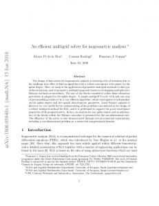
Figure 1: Left: Initial condition of water in a sphere. Middle: With standard solid boundary conditions, the liquid tends to unnaturally stick to the spherical boundary. Right: Considering separating boundary conditions lets the liquid to peel off the boundary easily. 1. A multigrid method for solving the Poisson equation resulting from the variational framework introduced in [BBB07] and [BB08]. 2. A modification to allow the solution of the LCP resulting from enforcing separating solid boundary conditions, which previously required an expensive QP solver. 2. Related Work Foster and Metaxas [FM96] were the first in computer graphics to simulate fluids by solving the Navier-Stokes equations on a staggered grid [HW65]. They voxelized the solids and enforced the proper boundary conditions between fluid and solid cells. Later, Foster and Fedkiw [FF01] simulated liquids by tracking the surface with the Level Set method. Numerical errors were reduced by the introduction of Lagrangian particles. They handled solid coupling by explicitly setting normal velocities to zero at solid boundaries and modified the pressure solver to not change these velocities. The method for handling solid boundaries was further improved by Houston et al. [HBW03]. They proposed to constrain the velocity extrapolated into the solid. Ramussen et al. [REN∗ 04] extended this method to properly handle the Level Set advection step. These methods work well when solid boundaries have the restriction that they are aligned with the grid faces. However, they fail in more general cases, e.g. in the scenario of a liquid settling in a non-axis aligned container. The reason is that the pressure solver only "sees" the voxelized solid and therefore, cannot cancel out the gravity force modified by these approaches. Batty et al. [BBB07] introduced a variational framework to properly handle solidfluid coupling. They considered separating solid boundary conditions with the result that liquids correctly peel off solid walls in their simulations but at the price of requiring an expensive LCP solver. Narain et al. [NGL10] simulated granular materials using an Eulerian grid. Their formulation of the pressure equation inside the material also results in an
LCP which they solve with an efficient Conjugate Gradientlike QP solver presented in [DS05]. Our work attempts to solve the LCP of Batty et al. [BBB07] more quickly using a modified multigrid solver. The multigrid method [McC87] has been used in various fields in computer graphics. Shi et al. [SYBF06] solved the Poisson equation for a deformation field with a multigrid approach to simulate deformable objects. Other examples in solid simulation are Zhu et al. [ZSTB10] who solved the elasticity equations with a multigrid solver and Müller [Mue08] who introduced hierarchical position based dynamics. In fluid simulation, Chentanez et al. [CFL∗ 07] used the algebraic multigrid method to solve for the pressure field on a tetrahedral mesh. Molemaker et al. [MCPN08] handled obstacles with a multigrid solver using velocity projection. To speed up the pressure solver Lentine et al. [LZF10] proposed a simplified multigrid approach. They execute pressure projection on a coarse grid and multiple independent fine grids. Aleka et al. [MST10] used a multigrid solver as a Conjugate Gradient preconditioner. More recently, Chentanez and Müller [CM11] showed how to use the multigrid method directly for free-surface liquid simulations. It is their method that we extend in this paper to handle separating solid boundary conditions.
3. Methods We simulate liquids by solving the inviscid Euler Equations, ∂u f ∇p = −(u · ∇)u + − ∂t ρ ρ
(1)
with Dirichlet and Neumann boundary conditions, subject to the incompressibility constraint ∇ · u = 0,
(2)
c The Eurographics Association 2011.
Nuttapong Chentanez & Matthias Müller / A Multigrid Fluid Pressure Solver Handling Separating Solid Boundary Conditions
where u is the fluid velocity field, p the pressure, t time, ρ the fluid density and f the external forces. We solve these equations in the region where the Level Set φ is non-positive. φ is evolved by ∂φ = −u · ∇φ. ∂t
(3)
We discretize the simulation domain using a regular staggered grid and the variational framework presented in [BBB07] and [BB08] to allow for curved solid boundaries. The x, y and z components of fluid velocity u = (u, v, w) are stored at the center of the faces perpendicular to the x, y and z axis respectively. The scalar pressure p and the Level Set function φ are stored at the cell center. We use us = (us , vs , ws ) for the solid velocity and Vi, j,k for the fraction of non-solid matter, i.e. fluid and air in cell (i, j, k). The scalars Vi+ 1 , j,k , Vi, j+ 1 ,k , and Vi, j,k+ 1 represent the fraction 2 2 2 of non-solid matter in the overlapping cells along the x, y and z axes respectively. While we follow Batty et al. [BBB07] for time integration, we deviate from their approach by using our novel multigrid method for pressure projection.
3.1. Enforcing Incompressibility We denote the velocity field before enforcing the divergence free condition as u∗ . Following the variational framework in [BBB07], the pressure p that enforces the divergence free constraint can be found by minimizing the kinematic energy integrated over the liquid domain. We discretize the integration and set the derivative of the energy to zero, which yields a linear system of p ∗
L(p)i, j,k = D(u )i, j,k
(4)
for all cells where φi+1,y,k < 0. The left hand side term L(p)i, j,k is composed of the six components li+, j,k + li−, j,k + li, j+,k + li, j−,k + li, j,k+ + li, j,k− ,
(5)
where li+, j,k = Vi+ 1 , j,k (pi, j,k − pi+, j,k ).
(6)
2
The pressure values are ( φ pi, j,k φi+1,y,k i, j,k pi+, j,k = pi+1, j,k
The system is then subjected to the separating complementarity condition 0 ≤ p ⊥ (u − vsolid ) · nˆ ≥ 0.
if φi+1,y,k ≥ 0 otherwise.
(7)
The right hand side is D(u)i, j,k = d x (u)i, j,k + d y (u)i, j,k + d z (u)i, j,k ,
(8)
where the term d x (u)i, j,k is given by 1 (9) ∆x (Vi+ 12 , j,k ui+ 12 , j,k −Vi− 12 , j,k ui− 12 , j,k ) + s s (Vi+ 1 , j,k −Vi, j,k )ui+ 1 , j,k − (Vi− 1 , j,k −Vi, j,k )ui− 1 , j,k(.10) 2 2 2 2
(11)
This condition states that either both p ≥ 0 and (u − vsolid ) · nˆ = 0 are true or both p = 0 and (u − vsolid ) · nˆ ≥ 0 are true. After p is determined it is used to make u divergence free. Since the variational approach [BBB07] satisfies the ˝ ˝ KarushUKuhn UTucker (KKT) conditions, we only need to ensure p >= 0 to satisfy the complementariy conditions. In [BBB07], a PATH solver [FM98] based on Quadratic Programming (QP) is used to solve this problem at a high computational cost which limits the method to be applied to small 2D domains only. We propose to solve the system efficiently with a novel multigrid method. To show why a multigrid approach is well suited for solving the linear complementarity problem above, let us first write (4) in general matrix form without the complementarity condition. For each cell we have i, j,k
i+1, j,k
Ai, j,k pi, j,k + Ai, j,k
i−1, j,k
pi−1, j,k + . . . = bi, j,k , (12) where the Ai, j,k ’s are the matrix coefficients involving cell (i, j, k). Solving for the unknown pressure at this cell yields pi, j,k =
1 i, j,k
Ai, j,k
pi+1, j,k + Ai, j,k
i+1, j,k
(bi, j,k − Ai, j,k
i+1, j,k
pi+1, j,k − Ai, j,k
pi+1, j,k − . . .). (13)
Such a linear system can be solved efficiently by global methods like PCG. However, considering the complementarity condition (11) turns the simple equation (13) in each boundary cell into pi, j,k = max(0,
The values li−, j,k , li, j+,k , li, j−,k , li, j,k+ and li, j,k− are defined similarly.
c The Eurographics Association 2011.
The other terms d y (u)i, j,k and d z (u)i, j,k are defined similarly. This formulation incorporates the ghost fluid method [EF02] to enforce p = 0 at the liquid surface instead of the cell center and the variational framework of [BBB07] to achieve sub-grid accuracy. φ must be extrapolated to solid cells that are one cell away from liquid cells so that they are included as unknowns in the linear system. Moreover, the solid velocity us also needs to be extrapolated to nearby liquid faces.
1 i, j,k
Ai, j,k
i+1, j,k
(bi, j,k −Ai, j,k
i+1, j,k
pi+1, j,k −Ai, j,k
pi+1, j,k −. . .)). (14)
While the max operator prevents the system from being solved by PCG, it can easily be solved with a Projected Gauss-Seidel method by applying (14) iteratively. However, projected Gauss-Seidel converges much more slowly than global methods. Fortunately, there is a way to speed it up by using it as the building block of a multigrid solver. The basic idea behind our approach is therefore to replace the traditional Red-Black Gauss-Seidel (RGBS) iteration used in the smoothing step of a multigrid solver with the Projected RedBlack Gauss-Seidel (PRGBS) iteration. Strictly speaking, the complementarity condition must be
Nuttapong Chentanez & Matthias Müller / A Multigrid Fluid Pressure Solver Handling Separating Solid Boundary Conditions
enforced precisely at the solid-liquid interface that, in general, is not aligned with the cell boundary. To handle this more general case correctly all the pressure values pi, j,k around the interface have to be modified simultaneously to satisfy the condition. To enforce this non-aligned complementarity condition we iterate through all edges that cross the solid-liquid interface and check if the pressure at the interface is less than zero. In that case, we adjust the end point pressures to enforce zero pressure at the interface. The pressure modifications are not unique so we choose the ones that minimize the sum of the squared magnitude of the changes.
of the form Am pm = bm has to be solved. To down sample V m+1 to V m we use 8-to-1 average:
In practice, we found that the simpler method of enforcing p ≥ 0 at the center of solid cells next to liquid cells produces results that are hardly distinguishable from results generated with the more complicated method described above. Figure 2 and sequences in our accompanying videos show comparisons of the two methods. As the results show, the simpler method yields convincing wall separation behavior even in the presence of curved boundaries. Therefore, we will use the simple approach in the remainder of our paper because it simplifies the multigrid implementation considerably.
1. If the 8 φ-values all have the same sign or m < M −C we use the 8-to-1 average,
3.1.1. Multigrid Overview The number of levels of the grid hierarchy we use is determined by M = log2 min(Bx , By , Bz ), where Bx , By , and Bz are the number of cells along x, y, and z axes respectively. The finest level of the grid corresponds to the simulation grid with ∆xM = ∆x. Algorithm 1 summarizes our multigrid pressure solver. We modified the solver presented in [CM11] to handle the discretization used in [BBB07] and introduced our new method to handle separating solid boundary conditions. Algorithm 1 Multigrid 1: for m = M − 1 down to 1 do 2: Down sample φm+1 → φm and V m+1 → V m 3: end for 4: for m = M down to 1 do 5: Extrapolate φm to solid cells that are one cell away from liquid 6: Compute matrix Am for level m using Equation 4 7: end for 8: bM = D(u) 9: pM = 0 10: Compute pM min 11: for i = 1 to num_Full_Cycles do 12: Full_Cycle() 13: end for 14: for i = 1 to num_V_Cycles do 15: V_Cycle(M) 16: end for Each coarse grid is derived from the previous finer grid by collapsing eight cells into one. At each level, a linear system
m
Vi, j,k =
1 8
m+1
m+1
m+1
m+1
(V2i,2 j,2k + V2i+1,2 j,2k + V2i,2 j+1,2k + V2i+1,2 j+1,2k +
m+1 V2i,2 j,2k+1
m+1 + V2i+1,2 j,2k+1
m+1 + V2i,2 j+1,2k+1
m+1 + V2i+1,2 j+1,2k+1 ,
(15) (16)
where i, j, k can be half indices for faces. If a required value lies outside the simulation grid, the border value is used instead. To down sample φm+1 to φm we distinguish the following two cases as in [CM11]:
2. otherwise we use the average of the positive φ-values. The key idea is to ensure that air bubbles persist in the C finest levels. We set C = 2 in our simulations. Given all necessary quantities, we then use Equation 4 to compute the coefficients of the Am for each level. For smoothing, we use the PRBGS method. We solve the system in two parallel passes followed by a projection step to enforce separating solid boundary conditions. The projection step ensures that the pressure of each cell is greater than or equal to ( 0 if i, j, k is inside a solid M (17) pmini, j,k = −∞ otherwise. We use tri-linear interpolation for both the restriction and the prolongation operators. Algorithm 2 V_Cycle(m) 1: if m == 1 then 2: Solve the linear system, A1 p1 = b1 3: else 4: for i = 1 to num_Pre_Sweep do 5: Smooth(pm ) and enforce pm min (PRBGS) 6: end for 7: rm = bl − Apm 8: bm−1 = Restrict(rm ) 9: pm−1 = 0 10: if m > M − S then m m 11: pm−1 min = DownsampleSubtract(pmin , p ) 12: else 13: pm min = −∞ 14: end if 15: V_Cycle(m − 1) 16: pm = pm + Prolong(pm−1 ) 17: for i = 1 to num_Post_Sweep do 18: Smooth (pm ) and enforce pm min (PRBGS) 19: end for 20: end if The algorithms above are similar to the standard multigrid c The Eurographics Association 2011.
Nuttapong Chentanez & Matthias Müller / A Multigrid Fluid Pressure Solver Handling Separating Solid Boundary Conditions
Algorithm 3 Full_Cycle() tmp
normal relative velocity. Only with this modification does the liquid peel-off freely from solids.
M
1: p = p 2: Compute pM min
Case BallBox DambreakBox RotatedBox DambreakSphere
M 3: pM min − = p
4: 5: 6: 7: 8: 9: 10: 11: 12: 13: 14: 15: 16: 17: 18: 19: 20:
rM = bM − ApM for m = M − 1 down to 1 do rm = Restrict(rm+1 ) if m ≥ M − S then m+1 pm min = DownsampleSubtract(pmin , 0) else pm min = −∞ end if end for b1 = r1 Solve the linear system, A1 p1 = b1 for m = 2 to M do pm = Prolong(pm−1 ) bm = rm V_Cycle(m) end for pM = ptmp + pM
max
(18)
m DownsampleSubtract(pm min , p )i, j,k= (19) m (pm min 2i+a,2 j+b,2k+c − p2i+a,2 j+b,2k+c ). (20)
This essential step transfers the separating boundary constrains from fine to coarser grids taking the current pressure estimate into account. The function is only executed on the S finest levels because the separating boundary condition is not meaningful in coarse levels. We use S = 3 in all of our examples. 3.2. Surface Tracking For our 3D examples, we track the liquid surface using the particle based approach presented in [ZB05]. However, if a grid based approach is used, φ must be carefully extrapolated into solids for the method to work properly. For a solid cell next to a liquid cell whose pressure is zero, φ should be set to the positive distance to the solid surface, not the negative value extrapolated from the liquid. This is similar to what is proposed in [REN∗ 04] where the condition is based on the c The Eurographics Association 2011.
LCP 21.26 21.17 122.97 122.58
% Diff 11.89 12.07 12.01 11.77
4. Results
This statement enforces the separating solid boundary condition. The second modifications are made on lines 11 and 8 in Algorithms 2 and 3 respectively, where the function DownsampleSubtract is defined as
a,b,c∈{0,1}
No LCP 19.00 18.89 109.78 109.67
Table 1: Average computation time for the multigrid solvers in millisecond for various examples, running on an NVIDIA GTX480. The solvers use 3 Full-Cycles followed by 4 VCycles with num_Pre_Sweep = num_Post_Sweep = 4. The column labeled with "Res" contains the grid resolutions whereas columns "No LCP" and "LCP" show the timings for the cases of sticky and separating solid boundary conditions respectively. The relative difference between the running times are listed in the last column.
algorithms with the newly added steps involving the minimum pressure pM min . The first modifications are made in lines 5 and 18 of Algorithm 2. While smoothing, i.e. executing Gauss-Seidel iterations, we enforce pm min . More precisely, we set m m pm i, j,k = max(pi, j,k , pmin i, j,k ).
Res 643 643 1283 1283
We first performed a 2D test to compare the results between 1) not enforcing separating solid boundary conditions, 2) enforcing the conditions at node level and 3) enforcing them at the edge level. Figure 2 shows the same frame for each case. As can be seen in image b), enforcing standard boundary conditions produces artifacts of liquid sticking to the surrounding sphere. The node based and the edge based approaches do not show these artifacts and the visual results are similar. We also implemented a GPU accelerated 3D version of our multigrid algorithm using CUDA and performed several further tests: a dam break scene in a spherical container, in a box rotated by 45 degree and in an axis aligned box. These examples are shown in Figures 1, 3 and 4 respectively. Figure 5 shows a fourth scene in which a ball of liquid splashes against the wall of a rectangular tank. In all tests we compare the results between enforcing sticky and separating solid boundary conditions at nodes. The artifact of water sticking to the walls when using the sticky boundary conditions is clearly visible in all cases. To test the efficiency of our approach we compare the performance of the LCP multigrid solver against a traditional multigrid solver. For our tests we used an NVIDIA GTX480. All timings are shown in Table 1. We found in all cases, that the LCP solver is only about 12% slower than a standard solver. We did not directly compare the performance of our solver with the performance of the PATH solver used in [BBB07]. However, we expect our solver to be several orders of magnitude faster. The reason is that our solver is comparable in speed with the multigrid solver of [CM11], which was reported to be up to 14 times faster than the preconditioned Conjugate Gradients (PCG) method. PCG was the solver Batty et al. [BBB07] used for their 3D examples and pointed out that the PATH solver was too slow to be
Nuttapong Chentanez & Matthias Müller / A Multigrid Fluid Pressure Solver Handling Separating Solid Boundary Conditions
practical for 3D domains. Dostal et al. [DS05] proposed a QP solver based on PCG. Due to the speedup we measured against PCG, we expect our multigrid solver to be significantly faster in this case as well especially for high resolution grids. 5. Conclusion and Future Work In conclusion, we presented a novel multigrid method for pressure projection handing separating solid boundary conditions. We demonstrated the effectiveness of the algorithm at eliminating the artifacts of water sticking to walls in several practical scenarios. The main limitation of our method is that it only supports one-way solid to fluid coupling. Extending it to work with two-way solid and fluid coupling, such as by solving the linear system presented in [RMSG∗ 08] with multigrid, might be challenging and is an interesting problem for future research. References [BB08] BATTY C., B RIDSON R.: Accurate viscous free surfaces for buckling, coiling, and rotating liquids. In Proceedings of the 2008 ACM/Eurographics Symposium on Computer Animation (July 2008), pp. 219–228. 2, 3 [BBB07] BATTY C., B ERTAILS F., B RIDSON R.: A fast variational framework for accurate solid-fluid coupling. In Proc. SIGGRAPH (2007), p. 100. 1, 2, 3, 4, 5 [CFL∗ 07] C HENTANEZ N., F ELDMAN B. E., L ABELLE F., O’B RIEN J. F., S HEWCHUK J. R.: Liquid simulation on lattice-based tetrahedral meshes. In Proc. ACM SIGGRAPH/Eurographics Symposium on Computer Animation (2007), pp. 219–228. 2 [CM11] C HENTANEZ N., M ÜLLER M.: Real-time Eulerian water simulation using a restricted tall cell grid. In Proc. SIGGRAPH (2011). 2, 4, 5
[LZF10] L ENTINE M., Z HENG W., F EDKIW R.: A novel algorithm for incompressible flow using only a coarse grid projection. In Proc. SIGGRAPH (July 2010), pp. 114:1–114:9. 2 [McC87]
M C C ORMICK S. F.: Multigrid methods. 2
[MCPN08] M OLEMAKER J., C OHEN J. M., PATEL S., N OH J.: Low viscosity flow simulations for animation. In ACM SIGGRAPH/Eurographics Symposium on Computer Animation (2008), pp. 9–18. 2 [MST10] M C A DAMS A., S IFAKIS E., T ERAN J.: A parallel multigrid Poisson solver for fluids simulation on large grids. In Proc. ACM SIGGRAPH/Eurographics Symposium on Computer Animation (2010). 2 [Mue08] M UELLER M.: Hierarchical position based dynamics. Proceedings of Virtual Reality Interactions and Physical Simulations (2008). 2 [NGL10] NARAIN R., G OLAS A., L IN M. C.: Free-flowing granular materials with two-way solid coupling. ACM Trans. Graph. 29 (December 2010), 173:1–173:10. 2 [REN∗ 04] R ASMUSSEN N., E NRIGHT D., N GUYEN D., M ARINO S., S UMNER N., G EIGER W., H OON S., F EDKIW R.: Directable photorealistic liquids. In Proc. ACM SIGGRAPH/Eurographics Symposium on Computer Animation (July 2004), pp. 193–202. 2, 5 [RMSG∗ 08] ROBINSON -M OSHER A., S HINAR T., G RETARS SON J., S U J., F EDKIW R.: Two-way coupling of fluids to rigid and deformable solids and shells. In ACM SIGGRAPH 2008 papers (New York, NY, USA, 2008), SIGGRAPH ’08, ACM, pp. 46:1–46:9. 6 [SYBF06] S HI L., Y U Y., B ELL N., F ENG W.-W.: A fast multigrid algorithm for mesh deformation. In ACM SIGGRAPH 2006 Papers (New York, NY, USA, 2006), SIGGRAPH ’06, ACM, pp. 1108–1117. 2 [ZB05] Z HU Y., B RIDSON R.: Animating sand as a fluid. In Proc. SIGGRAPH (2005), pp. 965–972. 5 [ZSTB10] Z HU Y., S IFAKIS E., T ERAN J., B RANDT A.: An efficient multigrid method for the simulation of high-resolution elastic solids. ACM Trans. Graph. 29 (April 2010), 16:1–16:18. 2
[DS05] D OSTÁL Z., S CHÖBERL J.: Minimizing quadratic functions subject to bound constraints with the rate of convergence and finite termination. Comput. Optim. Appl. 30 (January 2005), 23–43. 2, 6 [EF02] E NRIGHT D., F EDKIW R.: Robust treatment of interfaces ˇ for fluid flows and computer graphics. In Computer GraphicsT, 9th Int. Conf. on Hyperbolic Problems Theory, Numerics, Applications (2002). 3 [FF01] F OSTER N., F EDKIW R.: Practical animation of liquids. In Proc. SIGGRAPH (Aug. 2001), pp. 23–30. 2 [FM96] F OSTER N., M ETAXAS D.: Realistic animation of liquids. Graph. Models Image Process. 58, 5 (1996), 471–483. 2 [FM98] F ERRIS M. C., M UNSON T. S.: Complementarity problems in gams and the path solver. Journal of Economic Dynamics and Control 24 (1998), 2000. 1, 3 [HBW03] H OUSTON B., B OND C., W IEBE M.: A unified approach for modeling complex occlusions in fluid simulations. In ACM SIGGRAPH 2003 Sketches & Applications (New York, NY, USA, 2003), SIGGRAPH ’03, ACM, pp. 1–1. 2 [HW65] H ARLOW F., W ELCH J.: Numerical calculation of timedependent viscous incompressible flow of fluid with a free surface. The Physics of Fluids 8 (1965), 2182–2189. 2 c The Eurographics Association 2011.
Nuttapong Chentanez & Matthias Müller / A Multigrid Fluid Pressure Solver Handling Separating Solid Boundary Conditions
Figure 2: a) Initial condition of a ball of water in a circle moving diagonally to right and upwards. b) Sticky solid boundary conditions. c) Separating solid boundary conditions enforced at the nodes. d) Separating solid boundary condition enforced on the edges. Methods c) and d) produce similar visual results.
Figure 3: Left: Initial condition of water in a box rotated by 45 degrees. Middle: Sticky solid boundary conditions. Right: Separating solid boundary conditions.
Figure 4: Left: Initial condition of water in a box. Middle: Sticky solid boundary condition. Right: Separating solid boundary condition.
Figure 5: Left: Initial condition of a sphere of water in a box. The sphere is moving to the left. Middle: Sticky solid boundary condition. Right: Separating solid boundary condition.
c The Eurographics Association 2011.