A Multilayered Design Approach for Efficient Hybrid 3D Photonics Network-on-chip Dharanidhar Dang, Biplab Patra, Rabi Mahapatra Department of Computer Sceince & Engineering Texas A&M University
{d.dharanidhar,biplab7777,rabi}@tamu.edu ABSTRACT
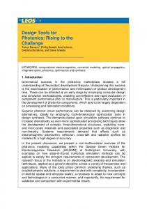
speed switching through Micro Ring Resonators[MRR] and low power optical waveguides as transmission medium we can achieve higher bandwidth by exploiting wavelength and mode[2]. PNoC is by far the most promising paradigm to meet the needs of the next generation on-chip communication. In this paper we propose a sandwich layered approach to design a 3D PNoC architecture by reducing the no. of laser components resulting in reduction in energy consumption and enhancement of aggregate bandwidth. We have incorporated MDM[3] along with WDM to increase the bandwidth of communication by manifolds. As shown in Fig.1 there are three layers as the basic design which can be repeatedly used to build multilayered 3D PNoC. The bottom and the top network layers include two 4X4 mesh of routers connecting processing cores along with multiplexers to carry out laser multiplexing. The sandwiched middle layer known as the laser layer includes mode-locked lasers and circular waveguides to route messages to the appropriate router. A high performance, low power, scalable and low cost photonic router is the heart of any high performance PNoC. In recent years several photonic router architectures have been proposed in the literature[4][5][6]. In this paper we use a high performance 5 port photonic router based on Cygnus router layout[2] incorporating MDM along with WDM and TDM to design a high performance and low power 3D PNoC.
In Chip Multiprocessors, traditional metallic interconnects will soon reach their bandwidth and energy dissipation limits. Photonic NoC (PNoC) is a promising alternative to renew higher performance in the advent of rising number of cores on chip. Efficient PNoC architectures are needed to reduce laser related energy consumption and maintain high performance. In this work we propose a novel sandwich layered approach to design a 3D PNoC architecture that is able to reduce no of hops, cross over points, and no of laser sources using multiplexing techniques. The 3D hybrid PNoC uses high performance 5X5 photonic routers incorporating mode division multiplexing (MDM) along with wavelength division multiplexing (WDM) and time division multiplexing (TDM). Experimental results demonstrates an increase in aggregated bandwidth up to 4x while reducing average energy consumption per router by 83% as compared to the recently reported results.
Categories and Subject Descriptors C.1 [Processor Architectures]: Multiple Data Stream Architectures; B.2.2 [Performance Analysis and Design Aids]: Simulation—Algorithms
General Terms Theory
Keywords Photonic Network-On-Chip, Mode Division Multiplexing
1.
INTRODUCTION
With rise in number of cores on a chip, there is a demand of new communication paradigm to accomodate large data traffic efficiently. In recent years photonic interconnections have emerged as the most relevant and attractive alternative to traditional electrical interconects[1]. With high Permission to make digital or hard copies of all or part of this work for personal or classroom use is granted without fee provided that copies are not made or distributed for profit or commercial advantage and that copies bear this notice and the full citation on the first page. Copyrights for components of this work owned by others than ACM must be honored. Abstracting with credit is permitted. To copy otherwise, or republish, to post on servers or to redistribute to lists, requires prior specific permission and/or a fee. Request permissions from
[email protected]. GLSVLSI ’15, May 20 - 22, 2015, Pittsburgh, PA, USA Copyright 2015 ACM 978-1-4503-3474-7/15/05 ...$15.00. http://dx.doi.org/10.1145/2742060.2742083.
Figure 1: Three layered Photonic mesh network
121
This paper has the following contributions:- (i) It has introduced a novel sandwiched laser-layered architecture as the basic building block for low power 3D PNoC architecture. This approach is the first of its kind to the best of our knowledge. (ii) It incorporates MDM along with WDM and TDM in routers to achieve higher bandwidth and lower power as compared to earlier works. (iii) The results from experiments indicate that :- The bandwidth of communication is about 40 Gbps which is about 4X higher than the recently reported results in[6]. The average energy consumption per router is about 83% lesser than the best reported result in[5]. The insertion loss is reported to be -2dB for the longest optical path which is about 75% less than the recently reported result in[7]. The paper is organized as follows. Section 2 describes the background information on PNoC, 3D stacking and the various building blocks for the proposed PNoC. The architecture of the proposed Sandwich Layered PNoC is described in Section 3. The experiments and results along with the comparative analysis with other photonic routers in literature are presented in Section 4. We conclude the paper in Section 5 with some directions for the future work.
2.
signals from Waveguide A to Waveguide B positioned in the rectangular direction.
(a) Reverse Switch(OFF State)
BUILDING BLOCKS OF THE ARCHITECTURE
Several 2D Photonic NoC architectures based on mesh[2], torus[1], crossbar[8] and clos[9] topologies have been proposed in recent years. To decrease cross sectional area and crossover points several 3D topologies have also been proposed[5][7]. But there is little attempt to reduce the number of laser components in designing a PNoC which is the primary source of power consumption. The topology we adopted for our design is a 4X4 2D mesh in the network layers. The important building blocks here are routers using MRR based Switches, Through-Silicon Vias(TSVs), and multiplexers for laser multiplexing.
2.1
(c) Rectangular Switch(OFF State)
(b) Reverse Switch(ON State)
(d) Rectangular (ON State)
Switch
Figure 2: MRR Switching There are two types of switching arrangements namely 1Reverse switching and 2- Rectangular Switching. Reverse switching deflects the optical signal by 180 degrees with a parallel arrangement of waveguides as shown in Fig.2a and Fig.2b. To switch the optical signal in a 90 degree angle we have an orthogonal arrangement of waveguides known as Rectangular Switching. It may be noted that the parallel reverse switching can also be done by combining two rectangular switches but that would result in two crossover points leading to cross talk and also use of an extra MRR. In the Reverse Switching arrangement as shown in the Fig.2a and Fig.2b the 180 degree deflection takes place without any crossover points and one MRR only. It results in reduction in insertion loss which is about 0.12dB per waveguide crossing and also power as MRR needs a DC current to switch ON and consumes less than 20uW[10].The switching time of MRR is very small and it is 10ps in our case. The photonic router layout as shown in Fig.3 adapted from Cygnus router[2] is composed of a photonic switching fabric made by combining 16 reverse and rectangular switches as mentioned above along with multimode waveguides and a network interface(NI). The router has five bidirectional ports viz. East, West, North, South and the NI port. Each photonic router has a controller within NI for selecting wavelength and mode for optical signal transmission. The router can operate simultaneously on multiple wavelengths using WDM with wavelength spacing equal to the free spectrum range of the MRR. The proposed layout consists of only 14 waveguide crossings, 16 MRRs in the switching fabric and 2 MRRs within NI to set up MDM leading to an optimized design. The NI (Fig.4) is the main control center in the router which comprises of a WDM + MDM + TDM based electrical to optical(E/O) converter, an optical to electrical(O/E) converter and an electrical controller. The E/O converter includes the mode locked laser along with MRR and waveguide arrangements facilitating MDM[3]. This has been shown in
ROUTER ARCHITECTURE: SWITCHING AND LAYOUT
The photonic router used in the proposed architecture is a 5X5 non-blocking with 5 I/O ports[14]. The communication techniques used in PNoCs are typically of two types. 1- Deterministic switching and 2- Dynamic Switching. In deterministic switching technique, a fixed routing pattern is defined during the network design and optical path between source-destination pair is established by dynamically selecting a specific wavelength[9]. This technique is typically used in wavelength selective passive networks. On the other hand, in dynamic switching technology, routing pattern is dynamically selected by an electronic controller[1][2]. This technique is similar to circuit switching. Though the former technique exhibits a lower latency than the later[8] but circuit switching networks provide higher aggregate bandwidth by adopting MDM along with WDM and TDM. They are also compact and scalable[4]. The basic switching element MRR is a circularly coiled waveguide which has the property of rotating the optical signal in clockwise direction. The switching time of the MRR is around 10ps. Fig.2a and Fig.2c shows MRRs in OFF condition that allow optical signals to flow from input port to the output labelled as straight port without deflection. However when MRRs are ON (Fig.2b and Fig.2d) they couple the optical
122
Figure 5: Mode Locked Laser employing MDM Figure 3: Logical layout of 5 × 5 photonic router Mode Locked Laser(MLL) in the same layer, selected by the corresponding 4X1 MUX in the network layer. Each laser serves four routers contrary to one laser per router as in almost all PNoC architectures recently proposed.
3.1
Figure 4: MDM Integrated Network Interface Fig.5. This results in higher aggregate bandwidth compared to all the previously proposed PNoC architectures.
2.2
MULTILAYER STACKING
Multiple electrical layers for building a 3D architecture are connected with each other by through-silicon-vias(TSVs). The proposed multilayer sandwiched architecture uses TSVs for communication between the laser layer and the network layers. TSVs have very small cross-sectional diameter(4um10um) and extremely small delay(20 ps for a 20 layer -3D stack)[5]
3.
MECHANISM AND CONTROL
If a source core ’s’ wants to send message to a destination core ’d’, it first sends a READY signal to the corresponding 4X1 multiplexer (MUX) to check its availability. As it follows the circuit switching mechanism so the route to be followed from source to destination is figured out as soon as the READY signal reaches the MUX. After receiving the acknowledgement from MUX, the core sends the message to the mode locked laser through MUX via TSV. The mode locked laser is controlled by the electronic controller present in the router. It adaptively selects the wavelength and the mode on which the message is to be relayed until the destination core. The controller uses the algorithm as depicted in Algorithm 1.
BASIC SANDWICHED LASER-LAYERED PNOC ARCHITECTURE
In the proposed 3 layer sandwiched PNoC architecture, both the top and the bottom layers are network layers and the middle sandwiched layer is the laser layer. Each of the network layers consist of a 2D mesh network of 16 cores interconnected by 16, 5X5 non-blocking photonic routers as described in Section II. Apart from that there are multimodal waveguides with two channels incorporating WDM and four 4X1 MUXs each dedicated to each of the 4 routers as shown in Fig.1. In the proposed design the laser layer consists of several waveguides which act as channels to relay the information from a source router to a destination router through the
To relay messages from the top to the bottom layer and vice versa there is one MRR in the laser layer corresponding to each router which helps in tapping the message as it is relayed in the common waveguide channel from the corresponding mode locked laser. From the above arrangement we can see that with only four lasers we are able to serve 32 cores simultaneously. The various experiments carried out, results and a thorough comparative analysis are presented in the next section.
4.
EXPERIMENTS AND RESULTS
IPKISS[11] platform has been used for design and simulation of the 3 layer sandwiched PNoC. This tool allows photonic layout design, virtual fabrication of components in different technologies, physical simulation of components, and optical circuit design and simulation. We custom designed photonic components like MRR, waveguide, modelocked laser, tapered waveguide, and photodiode required for the proposed architecture. Virtual Fabrication was done in order to validate the components.
123
Procedure Core1(s) wants to send Data to Core2(d) Data: N= no. of signals transmitting fully or partially along the path if N=0 then Switch ON M RR0 with λ0 ; Send Signal from Mode-Locked Laser; end if (N=1) and (mode=T E0 ) then Switch ON M RR1 with λ0 ; Send Signal from Mode-Locked Laser with a (τ + pulse-width) delay; end if (N=2) then Switch ON M RR0 with λ1 ; Send Signal from Mode-Locked Laser with a 2(τ + pulse-width) delay; end if (N=2) and (mode=T E0 ) then Switch ON M RR1 with λ1 ; Send Signal from Mode-Locked Laser with a 3(τ + pulse-width) delay; end
cation to cater design issues, we carried out simulation using CAMFR. CAMFR provides the refractive index profile and optical transmission profile of the fabricated design. Uniform refractive index across the PNoC is necessary for ripple free photonic transmission. After testing the uniformity of refractive index across the router, we simulated the 2-layer PNoC in CAPHE. CAPHE is an optical circuit simulator for time-domain and frequency-domain analysis. It is also used to evaluate the insertion loss in an optical circuit. The insertion loss in the MRR is found to be 0.12dB. Each MRR can be tuned to multiple wavelengths.
Algorithm 1: Controller Algorithm for adaptive mode division multiplexing
The no of MRRs used in a PNoC depicts its cross sectional footprint and cost. The number of MRRs used to design each of the 3-D PNoC architectures were compared. In the proposed 3 layer sandwiched PNoC Architecture, 19 MRRs per core are used. 16 MRRs for the router layout, 2 for facilitating WDM+MDM and 1 for tapping the message from the waveguide originating from the mode locked laser. So for 32 cores in the proposed design one needs 608 MRRs. The no of MRRs per core or router(each core associated with one router) for various 3D architectures were compared Fig.6. It is evident from the graph that the proposed architecture outperforms all others. The number of MRRs/Router for the proposed router architecture is about 32.1%, 24% and 17.3% less than R-3PO, Corona & Firefly respectively. Such reduction in the numberof MRRs directly reduces cross-sectional area and cross-over points on chip.
4.1
4.2
Comparative analysis
In this section the proposed PNoC architecture(PRO) design has been analytically compared with other 3D architectures like R-3PO[5],Corona[7], and Firefly[6]. Various parameters such as optical insertion loss, required no of MRRs and energy consumption for these architectures were analysed.
4.2.1
ARCHITECTURE SIMULATION IN IPKISS
The design parameters adopted to carry out various experiments are depicted in Table 1. MRR of diameter 10µm was adopted to keep the area of the PNoC foot-print as small as possible without letting the waveguides interfere much. The multimode waveguide in our design supports four optical modes T E0 , T E1 , T E2 and T E3 with a refractive index of 2.46. The waveguide also supports multiple wavelengths. The mode-locked laser used has a frequency of 10-GHz. It produces optical signal with a pulse width of 10ps. Each of the pulses contains multiple wavelengths ranging from 1595nm to 1605nm. The laser also produces hundreds of modes. But we are considering modes T E0 , T E1 , T E2 and T E3 as the proposed MDM scheme supports 4 modes. Using all these fundamental components, we built the 3 layer sandwiched PNoC in IPKISS and performed the physical simulation. MRRs and waveguides were integrated to virtually fab-
Number Of MRRs
25
20 R3P
Table 1: Design Parameters for Experimental Setup Design Parameters Value MRR diameter 10µm Waveguide(MRR) width 450nm Waveguide(Signal Transmission) height 250nm Waveguide(Signal Transmission) width 450nm Refractive index Of waveguides 2.46 Pulse-width of Optical Signal 10ps Frequency(mode-locked laser) 10GHz Wavelength 1547.5nm& 1550nm
COR
FIR
PRO
Figure 6: Comparing number of MRRs/Router for different PNoC architectures; R3P:R3PO, COR:Corona, FIR:Firefly, PRO:proposed sandwiched-3 layer PNoC
4.2.2
Energy Consumption
The total energy consumption in PNoC architectures can be divided into two categories :- optical energy and electrical energy. Electrical energy is consumed by the electrical controller and the optical energy consumption is the sum of laser energy and energy dissipated in the photonic switching fabric.
ricate the router. Routers, lasers, TSVs, and waveguides were connected and virtually fabricated. After virtual fabri-
124
The laser energy can be determined by the following equation PLaser = PDet + PChannel + MSys
1.5 1
(1)
Here PDet is the photo-detector sensitivity. Pchannel is the photonic channel loss and Msys is the system margin. The optical insertion loss is the loss in signal power whenever there is a waveguide crossing or bending. The total optical insertion loss is determined by X X X LInsertion = LBending + LCrossing + LM RR (2)
0.5 FIR
COR
R3P
PRO
Figure 7: Comparison of energy consumption per router in fJ/bit
As per the Equation 2, insertion loss in an optical path accounts for the total no of bendings and crossings of waveguides and MRRs in the message path. To maintain the uniformity and have a fair comparison with other architectures we use the same optical device parameters and loss values as listed in Table 2. The primary function of the electrical
6 5 4
Table 2: Electrical and optical losses Component Value Unit Laser efficiency Splitter Ring Drop Photodetector Sensitivity
5 0.2 1 -26
FIR
dB dB/cm dB dBm
COR
R3P
PRO
Figure 8: Comparison of average energy consumption per optical path, in fJ/bit
the proposed router and the Corona architecture are almost overlapping with negligible difference.
controller is to turn the MRRs ON and OFF. The number of MRRs encountered while the message is relayed from source to destination is determined by the routing algorithm and also the amount of traffic. We analytically determined the electrical energy consumption of the proposed design by dimension order routing scheme. We evaluated the average energy consumption per optical path in the network (Ppath ) and also the average energy consumption per router (Prouter ). We calculated Ppath using Equation 3. Here Pj represents the energy consumed on j-th path when the bandwidth is ’B’. ’P ∗ ’ represents the total number of photonic paths in the NoC. Prouter is calculated using Equation 4 where ’R’ is the average number of photonic routers in all the optical paths. PP ∗ j=1 Pj (3) Ppath = ∗ P ×B
4.2.3
Optical Insertion Loss
Insertion loss is the loss of signal power whenever a crossing or bending is encountered in a waveguide along the transmission path which includes transferring the optical signal into the MRR. Insertion loss in a NoC determines its feasibility and also the power required by the NI of the router in this case to transmit and receive optical signals. The optical signal must be transmitted with sufficient power so that they can be received in a proper form at the destination. Insertion Loss for an MRR and waveguide crossings are 0.5dB and 0.12 dB respectively. Insertion Loss varies across input-output pairs in a network. Hence we evaluated the best-case, average-case, and the worst-case insertion losses in all the architectures. It is clear from the result shown in Fig. 10 that the proposed architecture has the lowest insertion loss among all the cases. Compared to R-3PO the proposed router has 65% less best case loss, 45% less average-case loss and 30% less worst-case loss.
Ppath (4) R Network-level analysis in Fig.8 shows that the proposed 3D PNoC consumes the average energy per optical path of about 4.8fJ/bit. It is about 20% less than Firefly and almost equal to the Corona architecture. Though as compared to R3PO the average energy per optical path is more but it gets balanced as R3PO has a higher insertion loss. In the proposed router based network, average router energy consumption is 0.32fJ/bit, which is also 83% less than the Corona architecture as shown in Fig.7. The MRRs in the routers of the proposed archirecture are placed in such a manner that it does not need to switch on any MRR for a packet to travel along the row or column. This makes the proposed 3D PNoC highly scalable without worrying about the energy consumption in additional routers on a longer path. From Fig.9 we can see the variation in average energy/path in fJ/bit for different NoC sizes. The graph corresponding to Prouter =
4.3
Bandwidth Comparison
Photonic-links deployed in the proposed PNoC has a data rate of 10-Gbps. Deploying MDM and WDM, the proposed architecture offers an overall bandwidth of 40-Gbps. The architecture enhances the photonic-link data rate by 4× compared to 1× enhancement in the most recently reported architecture[5].
4.4
Number of Laser-sources
The laser-multiplexing technique deployed in the proposed architecture allows each laser-source to serve eight cores. This technique reduces the number of on-chip lasers by 87.25% compared to architectures deploying one laser-source per core[6].
125
Energy/Path in fJ/bit
[3] L. Luo, N. Ophir, C. Chen, L. Gabrielli, C. Poitras, K. Bergmen and M. Lipson, WDM-compatible mode-division multiplexing on a silicon chip, Nature Communications5,Article number:3069,15 January 2014 [4] L. Yang, R. Ji, L. Zhang, Y. Tian, J. Ding, H. Chen, Y. Lu, P. Zhou and W. jhu Five-port optical router for photonic networks-on-chip,Optics Express, Vol. 19, Issue 21, pp. 20258-20268 (2011) [5] R. Morris, A.K. Kodi, and A. Louri, Dynamic Reconfiguration of 3D Photonic Networks-on-Chip for Maximizing Performance and Improving Fault Tolerance, ,MICRO, 2012, pp.282-293. [6] Y. Pan, P. Kumar, J. Kim, G. Memik, Y. Zhang, A. Choudhary, Firefly: Illuminating future network-on-chip with nanophotonics, Int’l Symposium on Computer Architecture (ISCA), 2009. [7] D. Vantrease et al. Corona: System Implications of Emerging Nanophotonic Technology,35th International Symposium on Computer Architecture, 2008. ISCA ’08. [8] C. Batten et al. Building manycore processor to DRAM networks with monolithic silicon photonics, High-Performance Interconnects, Symposium on, pp. 21-30, 16th IEEE Symposium on High Performance Interconnects, (2008). [9] A. Joshi, C. Batten, Y.J. Kwon, S. Beamer, I. Shamim, K. Asanovic, and V. Stojanovic, Silicon-photonic clos networks for global on-chip communication, 2009 3rd ACM/IEEE International Symposium on Networks-on-Chip, 124-133 (2009). [10] A. W. Poon, F. Xu, X. Luo, Cascaded active silicon microresonator array cross-connect circuits for WDM networks-on-chip,Proc. SPIE Int.Soc. Opt. Eng. 6898, 689812, 2008. [11] IPKISS - a generic and modular software framework for parametric design www.ipkiss.org [12] A. Bianco et al. Scalability of optical interconnects based on microring resonators IEEE Photon. Technol. Lett.22(15), 1081-1083 (2010) [13] Y. Xie et al.Crosstalk noise and bit error rate analysis for optical network-on-chip, 47th ACM/EDAC/IEEE Design Automation Conference, 657-660 (2010) [14] Dang, D.; Patra, B.; Mahapatra, R.; Fiers, M., Mode-Division-Multiplexed Photonic Router for High Performance Network-on-Chip, VLSI Design (VLSID), 2015 28th International Conference on , vol., no., pp.111,116, 3-7 Jan. 2015
PRO R3P COR FIR
20
10
32
72
128
200
NoC size(total no. of cores) Figure 9: Average energy per Path for different NoC sizes 10
Worst case Best case Average case
5
0 COR
R3P
PRO
Figure 10: Insertion loss in 4 × 4 PNoC in dB
5.
CONCLUSION
This article introduced a sandwiched 3 layer PNoC architecture and a high performance photonic router microarchitecture by integrating WDM, MDM and TDM techniques. A virtual prototype implementation demonstrates significant improvements in the performance and energy consumption as compared to some other PNoC architectures. This approach can be extended to realize efficient multilayer 3D PNoC designs in the future. A network simulator will be designed to demonstrate the behaviour and eficiency of the proposed architecture in different types of traffic scenarios. MRR properties vary with temperature which affects the overall performance of PNoC. Research will be carried out to design an efficient thermal model of PNoC.
6.
ACKNOWLEDGMENTS
The authors acknowledge the support of Luceda Photonics, Belgium for providing IPKISS and CAPHE tools to validate photonic components and cicuits used in the experiment.
7.
REFERENCES
[1] A. Shacham, K. Bergman, and L.P. Carloni, Photonic networks-on-chip for future generations of chip multiprocessors,, IEEE Trans. Comput.57(9), 1246-1260 (2008). [2] H.X. Gu, K.H. Mo, J. Xu, and W. Zhang, A low-power low-cost optical router for optical networks-on-chip in multiprocessor systems-on-chip, 2009 IEEE Computer Society Annual Symposium on VlSI, 19-24 (2009).
126