(Holstein 1942, Kossack 1947, Norton 1972). Photoelectric .... Trumpeter Swan (Cygnus Cygnus buccinator), Canada Goose (Branta can- adensis), Wood Duck ...
Wilson Bull., 93(3), 1981, pp. 325-333
A MULTIPLE
SENSOR SYSTEM FOR MONITORING AVIAN NESTING BEHAVIOR
JAMES A. COOPER AND ALAN D. AFTON
Avian nest construction,
laying and incubation
time budgets often pro-
vide a temporal framework for ethological, physiological and ecological investigations. Numerous methods have been devised to measure nest attentive and inattentive (1952:s)
periods. Early approaches,
and Skutch (1962), involved
observations
reviewed by Kendeigh from a blind or simple
mechanical switch devices connected to graphic recorders. Advances electronic and photographic equipment have led to the development many useful instruments
for detecting
the presence
in of
of birds at or near
nests. Thermistors and thermocouples have been positioned in nests (Baldwin and Kendeigh 1927, Farner 1958, Norton 1972), in eggs (Huggins 1941, Snelling 1972, Caldwell and Cornwell 1975 and others), or in artificial eggs (Holstein
1942, Kossack
1947, Norton
1972). Photoelectric
placed in or near nests by Kessler (1962) and Weeden lapse cameras were used by Weller Cornwell
(1975).
Gilmer
sensors were
(1966), while time
and Derksen (1972) and Caldwell and V arney and Ellis (1974) and Miller
et al. (1971),
(1976) have described telemetry systems. Pulliainen (1978) recently ployed closed-circuit television to record nesting behavior.
em-
Each approach reflected the limitations imposed by the species studied, the availability and cost of electronic and photographic equipment and the inventiveness of the investigator(s). Skutch (1962) emphasized, and we believe correctly, that automatic monitors cannot substitute for observation. Yet, investigations of individual variation or nocturnally active birds cannot easily be done by observation quire expensive night-vision
equipment,
alone.
Nocturnal
observations
re-
and large samples are necessary
for statistical analysis of differences among individual birds. Varney and Ellis (1974) criticized thermistor and thermocouple techniques because a wire must be attached to an egg; they recommended a telemetry system in an artificial egg. However, artificial egg temperatures differ from heat levels in developing sor, not allowing
eggs (Drent 1970). Earlier
crosschecking
of egg temperatures,
incubating
for accuracy bird behavior
methods used a single senor simultaneous
monitoring
or identity.
This paper describes the construction and field application of a multiple sensor (photoelectric-thermistor-photographic) system for nesting studies. While employed primarily in waterfowl investigations to date, the apparatus has potential for studies of a wide range of species.
325
THE WILSON BULLETIN
326
* Vol. 93, No. 3, September 1981
INDEPENDENT MODE
; NEST
DEPENDENT MODE
I NEST
I
Weather
Proof
, I
Case
FIG. 1.
Instrument
;
Proof
Case
Block diagram of the multiple sensor system. METHODS
an infrared
Weather
AND MATERIALS
design and construction.-Basic photoelectric
instrument
relay (Microswitch
MLS3A),
components a medical
are:
therm-
istor (Rustrak 1331), a super-8 movie camera (Minolta XL-401), a stripchart, temperature-event recorder (Rustrak 2133), an infrared relay interface and a 1.5 VDC clock (Fig. 1). The recorder, interface and clock are housed in a weather-proof case. The infrared relay and camera are positioned near or at the nest and connected
to the recorder
and interface,
and the thermistor probe is inserted in an egg or in the nest. Connections are via multi-conductor, insulated cable. The recorder, thermistor and relay are powered by one or two 12 VDC batteries; the clock and camera are driven by rechargeable 1.5 VDC dry cells. Detectors may be operated independently or in concert. The presence of a bird at the nest is detected when the infrared beam is blocked by the bird’s body. Interruption of the 5-mm diameter beam, projected from the lens of the relay to an 8-cm plastic reflector and back to the relay, closes the circuit between the relay and the interface, which, in turn, closes the circuit to the event channel of the recorder
(Fig. 1). The interface
(Fig. 2)
is necessary because the infrared relay switching transistor has a maximum current limit of 120 mA and the minimum current needed to activate the event pen is 500 mA. When thermistor
monitors
the bird’s
inserted presence
in the egg air cell or nest, the by recording
cooling during an
Cooper and A.fion * NESTING
BEHAVIOR
327
MONITOR
BATTERY
MLS-3A
I MLS-3A
EVENT PEN &
LOAD
CAMERA RELAY
FIG. 2.
Schematic diagram of infrared relay-recorder interface.
absence. In independent mode, the camera shutter is activated by an internal timer at preselected intervals over a range of l-60 set, recording on film the nest and its surroundings during daylight and by using a strobelight at night.
In dependent
mode, single frame
exposures
are triggered
by interruption of the infrared beam so that the animal blocking the beam is photographed. An independent time reference is needed for the recorder because the chart speed varies with the battery
voltage, which is a function
of power
demand, battery condition and temperature. This is attained by opening briefly the thermistor circuit once an hour. A magnetic reed switch attached to the noon position of the clock with a small magnet glued to the minute hand provides an inexpensive
but accurate reference.
Humid conditions may cause chart paper jamming. This can be prevented by encasing the recorder in an airtight case containing a noncorrosive desiccant (CaSO,). Field
application.-The
12 VDC
power supply permits
monitoring
in
328
THE WILSON
remote locations
BULLETIN
* Vol. 93, No. 3, September 1981
and the cable connections
allow maintenance
of the re-
corder without disturbing the bird at the nest. Installation timing and configuration depend on the characteristics of the species being studied. A typical application
entails locating a nest, preferably
ing or early laying stages, and choosing or constructing the instrument case; placement of the relay, thermistor
during the prelaya suitable site for probe, camera or
combination of these at the nest completes the process. The infrared relay installation depends on the physical construction of the nest, the posture of the sitting bird, the size of target it provides and the substrate on which the nest is built.
Nests constructed
on stable sub-
strate, e.g., most dabbling duck nests, present little difficulty. ened, metal angle-irons
Two sharp-
are driven into the soil on a line bisecting the nest
cup and the relay is bolted to 1 stake, the reflector to the other. The infrared beam is adjusted by moving the relay and reflector vertically until the beam is broken by the sitting bird’s
body. The possibility
that vege-
tation or nest materials will block the beam can be reduced by placing the relay and reflector as close as possible to the rim of the nest cup. In addition, small boards can be positioned between the nest cup and the relay and reflector to arrest growth of vegetation. Prior to installation exposed surfaces
should be painted
to match
the colors at the nest-site.
Relay installation at overwater nests with an unstable substrate, e.g., nests of most diving ducks, is accomplished by driving 2 metal rods into the marsh bottom.
The relay and reflector
aligned in the same manner
are then attached
to the rods and
as in the case of a ground nest. When mon-
itoring cavity nesting birds, the relay and reflector are fastened to brackets and aligned so that the bird interrupts the beam when entering or departing. The thermistor probe is inserted into an egg using a technique similar to that of Caldwell and Cornwell (1975:709). The egg air cell is located with a flashlight
and outlined on the egg shell with a pencil;
a small (0.8
mm) hole is drilled in the shell at the apex of the air-cell end with a sterile bit, taking
care not to perforate
the air-cell
membrane,
and the hole is
enlarged with a sterile scalpel to accommodate the thermistor. The probe, dipped in alcohol and allowed to dry, is inserted adjacent to the air-cell membrane and the hole sealed with epoxy glue (Fig. 3). The termistor wire is then taped to the long axis of the egg with adhesive tape. After inserting the probe, the egg is placed in the nest, the probe wire drawn through the bottom of the cup and out the side of the nest. For species in which the egg air cells are too small to accept the probe, e.g., Spotted Sandpiper the probe may be glued to the side of an egg, placed
(Actilis macularia),
in an artificial egg, or fastened to the bottom of the nest. Unlike the silent, infrared relay, the camera emits a faint click when
Cooper and Afton - NESTING
THERMISTOR
EPOXY
BEHAVIOR
329
MONITOR
TAPE
GLUE
\ AIR CELL
FIG. 3.
the shutter releases. sufficient
distance
photographic
Diagram of thermistor implantation in an egg.
Thus,
the camera
monitoring in independent
be set at a l-60
and tripod must be positioned
from the nest to avoid frightening
set interval,
selection
the bird.
mode is not continuous,
a
Because i.e., must
of the shutter release rate is im-
portant. If the frequencies of brief activities, e.g., egg turning and preening on the nest, are to be measured, the interval must be less than the minimum duration of these behaviors. A clock placed in the field of view simplifies the film analysis. For species monitored to date, a chart speed of 5 cm/h allowed measurement
of periods on or off the nest to the nearest minute.
Chart rolls
are 19.2 m long, hence, a paper change is necessary every 15 days. A more rapid speed, attained by a simple and inexpensive gear change, would be necessary for accurate measurement of activities of shorter duration. The frequency
of battery
change depends on the condition
of the bat-
teries, length of connecting sensor cables and temperature. Using the infrared relay, the thermistor and the camera in dependent mode with 33 m of cable, a single 65 A-h battery will provide power for 4 days; 2 batteries in parallel last 8 days. We found that changes at 24-day intervals are best. Replacement of the camera batteries with each film change reduces the possibility of power failure during a monitoring session. Individual cables or a single multiconductor to the detectors
may be
used. Cables need not be shielded but must be waterproof and sufficiently durable to withstand months in the field. The infrared relay requires 3
330
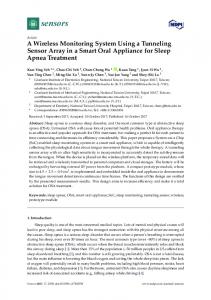
FIG. 4.
THE
Three-h
showing departure temperature
WILSON
recording
* Vol. 93, No. 3, September 1981
BULLETIN
of the activity
of an incubating
from cavity at 05:16 (OFF)
and return
Wood Duck:
at 06:58 (ON)
(A) event channel and (B) egg air cell
in “C. Breaks in B denote l-h intervals.
conductors while the thermistor
and camera 2 each. By cutting cables into
33 m lengths and using waterproof connectors, one may extend the cable needed to reach the nest from the recorder. The advantage of this is that the added power demand of the longer cable can be easily calculated.
The
battery must be changed 1 day sooner per 33 m of cable used. Thus, a monitor with two 33 m cable sections would require a battery change every 3 days vs 4 days for 1 with a single section. Cables at and near the nest should be secured by taping or tacking them down, then covered with vegetation or placed underwater. EXAMPLES
Species
monitored
employing
AND
DISCUSSION
components
of the system include:
the
Trumpeter Swan (Cygnus Cygnus buccinator), Canada Goose (Branta canadensis), Wood Duck (Aix sponsa), Pintail (Anus ucutu), American Wigeon (Anus americana), Gadwall (Anus strepera), Green-winged Teal (Anus creccu curolinensis), Blue-winged Teal (Anus discors), Northern Shoveler (Anus clypeutu), Lesser Scaup (Aythyu uffinis), Canvasback Zisneriu), Redhead (Aythyu americana), Ring-necked Duck
(Aythyu vul(Aythyu col-
Zuris), Ruddy Duck (Oxyuru jumuicensis), Western Grebe (Aechmophorus Spotted Sandpiper, Short-eared Owl (Asio jkmmeus) and occidentalis), Sharp-tailed
Grouse (Pedioecetes phusiunellus).
Based on data from 72 nests where the infrared relay and thermistor probe were employed, 32 of 1066 (3.07) o monitored days were lost due to
Cooper and .4&m
. NESTING
BEHAVIOR
331
MONITOR
DAY OF INCUBATION FIG.
5.
recorded
Example
of the nest attentiveness
using thermistor
and infrared
sensor or recorder failure.
of a Ruddy
Duck
female,
3-27
June
1975,
relay sensors.
Moreover,
no records of inattentive
and atten-
tive periods at the nest were lost when using 3 sensors (N = 10 nests, 216 days). Statistical treatment of incubation time budget data is difficult without relatively complete records; therefore, keeping instrument failures to a minimum is important. The multiple
sensor approach not only permits
recording
of prelaying,
laying and incubation time budgets, it also allows synchronous measures of egg air cell and/or nest air temperature and parent bird postures, displays, preening, sleep and other activities at the nest. An example of the recorder output for a Wood Duck recess is given in Fig. 4, and for a Ruddy Duck incubation attentiveness pattern in Fig. 5. Individuals frequenting a nest can be identified
on film if markers or unique characters
are present.
The cost of a unit with the 3 sensors is about $800 per monitor, and the construction is relatively simple. Except for the infrared relay, recorder, camera
and thermistor,
all components
chased in most electronic series circuits is needed
used in the system may be pur-
stores. A knowledge of simple DC parallel and to assemble or repair the interface and time-
reference circuits. The system may have minor disadvantages when used to monitor birds that are disturbed by the thermistor wire attached to the egg or nest, or by changing of the camera
film and batteries.
We have not encountered
332
THE WILSON
BULLETIN
* Vol. 93, No. 3, September 1981
the former and have found that 84.1% (N = 44) of the eggs with implanted thermistors
have hatched.
be difficult
to monitor
We suspect that species such as raptors may
using the thermistor
(see Varney
and Ellis 1974).
But the camera and infrared sensor would provide data in these cases. When the camera must be placed so close to the nest that the sitting bird is disturbed
during maintenance,
must be carefully
studied
the infrared
and thermistor
and the film and batteries
changed
recordings when the
bird is off the nest. This may be done for non-continuous incubating species but not for one in which both sexes incubate or others whose nest is constantly
attended. SUMMARY
The construction and field application of a multiple sensor (photoelectric-thermistor-photographic) system for avian nesting studies is described. The portable, battery-powered system has several advantages over previously described techniques. Foremost is the accurate and continuous recording of incubation time budgets. The system permits synchronous recordings of egg air cell and/or nest air temperature, postures, displays, preening, nest construction, and prelaying and incubation time budgets. ACKNOWLEDGMENTS We thank William H. Marshall and Milton W. Weller, Dept. Entomology, Fisheries and Wildlife, University of Minnesota, for reviewing the manuscript. John D. Afton assisted with the electrical design. Financial support was provided by the Graduate School and Minnesota Agricultural Experiment Station, University of Minnesota and the Delta Waterfowl Research Station, Portage La Prairie, Manitoba. This paper is No. 10,939 of the Scientific Journal Series of the Minnesota Agricultural Experiment Station. LITERATURE
CITED
BALDWIN, S. P. AND S. C. KENDEIGH. 1927. Attentiveness and inattentiveness in the nesting behavior of the House Wren. Auk 44:206-216. CALDWELL, P. J. AND G. W. CORNWELL. 1975. Incubation behavior and temperatures of the Mallard Duck. Auk 92:706-731. DRENT, R. 1970. Functional aspects of incubation in the Herring Gull (Larus argentatus). Behaviour Suppl. 17:1-132. FARNER, D. S. 1958. Incubation and body temperatures in the Yellow-eyed Penguin. Auk 75~249-262. GILMER, D. S., V. B. KUECHLE AND I. J. BALL. 1971. A device for monitoring radio-marked animals. J. Wildl. Manage. 35:829-832. HOLSTEIN, V. 1942. Duehogen, Astur gentilis dubivs (Sparrman). Biol. Stud. over Danske Rovfugle. I (Copenhagen). HUGGINS, R. A. 1941. Egg temperatures of wild birds under natural conditions. Ecology 22:148-157. KENDEIGH, S. C. 1952. Parental care and its evolution in birds. Illinois Biol. Monogr. 22:i48-157. KESSLER, F. 1962. Measurement of nest attentiveness in the Ring-necked Pheasant. Auk 79:702-705.
Cooper and Afton * NESTING
BEHAVIOR
333
MONITOR
KOSSACK, C. W. 1947. Incubation temperatures of Canada Geese. J. Wildl. Manage. 11:119-126. MILLER, K. J. 1976. Activity patterns, vocalization, and site selection in nesting Blue-winged Teal. Wildfowl 27:3343. NORTON, D. W. 1972. Incubation schedules of four species of calidridine sandpipers at Barrow, Alaska. Condor 74:164-176. PULLIAINEN, E. 1978. Behavior of a Willow Grouse Lagopus 1. lagopusat the nest. Ornis Stand. Fenn. 55:141-148. SKUTCH, A. F. 1962. The constancy of incubation. Wilson Bull. 74:115-152. SNELLING, J. C. 1972. Artificial incubation of Sparrow Hawk eggs. J. Wildl. Manage. 36: 1299-1304. VARNEY, J. R. AND D. J. ELLIS. 1974. Telemetering egg for use in incubation and nesting studies. J. Wildl. Manage. 38:142-148. WEEDEN, J. S. 1966. Diurnal rhythm of attentiveness of incubating female Tree Sparrows (Spizellaarborea)at a northern latitude. Auk 33:368-388. WELLER, M. W. AND D. V. DERKSEN. 1972. Use of time-lapse photography to study nesting activities of birds. Auk 89:196-200. DEPT.
ENTOMOLOGY,
PAUL,
MINNESOTA
RESEARCH
STATION,
AND
WILDLIFE,
55108. (PRESENT
FISHERIES
ADDRESS
PORTAGE
LA PRAIRIE,
UNIV.
MINNESOTA,
ADA: DELTA MANITOBA
ST.
WATERFOWL
RJN
3A1 CANA-
DA). ACCEPTED 15 JAN. 1981.
THE INTERNATIONAL
OSPREY FOUNDATION,
INC.
The International Osprey Foundation, Inc. (TIOF), a non-profit organization, has been formed to study the problems of restoring Osprey numbers to a stable population, make recommendations to enhance the continued survival of the Osprey and initiate education programs. Based on Sanible Island, Florida, TIOF monitors Osprey nests on the island and is responsible for an artificial nesting program already established there. A computerized list of Osprey researchers and a working bibliography are being compiled. For further information write: Mark A. Westall, President TIOF, 289 Southwinds, Sanibel, Florida 33957.