Jul 1, 2010 - The algorithms have been implemented in a cell com- piler (CELLO) working in an experimental silicon compiler en- vironment. 1 Introduction.
A New Approach to Optimal Cell Synthesis J a n Madsen Designcenter of Electronics Institute Technical University of Denmark DK2800 Lyngby, Denmark
General Design Aspects
Abstract
2
This paper presents a set of algorithms for optimal layout generation of CMOS complex gates. The algorithms are able to handle global physical constraints, such as pin placement, and to capture timing aspects. Results show that this new approach provides better solutions in area and speed compared t o other methods. The algorithms have been implemented in a cell compiler (CELLO) working in a n experimental silicon compiler environment.
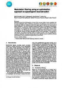
Using the line-of-diffusion layout style [SI, where physically adjacent transistors may share a common diffusion area, an optimal transistor ordering will maximize the number of shareable diffusion areas and minimize the number of diffusion gaps. However, a given transistor circuit might have several optimal orderings, all giving a minimal-width layout, but resulting in different heights. Figure 1 shows the layout of three different orderings of the same transistor circuit. Comparing the layout areas, it is obvious that an optimal ordering does not necessary lead t o an area-optimal layout. Further, the choice of ordering significantly influences the circuit performance (i.e. speed) as shown in Table 1, where the worst case propagation delays for the three circuits in Figure 1 are listed.
1
Introduction
Cell compilers, which translate a behavioral cell description into mask layout, makes it possible t o deal with much larger “cell libraries” than the usual standard cell approach, by replacing many primitive gates, such as NAND and NOR gates, with a single complez gate [8]. This method reduces layout area and improves performance. Algorithms pioneered by Uehara and vancleemput [SI, who introduced the idea of Euler paths and dual trails to obtain a layout in the line-of-diffusion layout style, have concentrated on specifying a graph theoretical model of the problem and finding an optimal solution. [5] generalized the work of [8] and proposed an optimal method based upon the same cell model. However they did not address the problem of reordering transistors in the netlist, which may be a considerable limitation as the order influences area as well as electrical performance. [3] propose an algorithm, which does not restrict transistor pairs to be aligned. Though this might have some advantages when trying to chain different cells, the cell height will increase due to a more complex routing within the cell. [2] propose an algorithm based upon the delayed binding concept, which produces a minimum width layout, i.e. an optimal transistor ordering. But as will be shown in the next section, minimum width does not imply minimum area. Common to these algorithms is, that an optimal solution is the one giving the smallest possible cell layout area, i.e. a local optimum. If, however, a global optimal solution is to be realized, global constraints have to be taken into account, e.g. the pin placement. So in order to fully utilize the flexibility of the cell compiler concept, it should be possible to handle pin placement as a constraint. This paper presents a set of algorithms able to handle a constrained pin placement for global optimization and still produce local optimal cell layout if possible.
b
d
C
Figure 1: The effect of transistor ordering on layout area: a) transistor circuit; b) order: a b d c; c) order: d c a b; d) order: bdca.
I l*l
Delay t p d ~ + ~1.60 k w - r , I 0.68
I
I 1.66 I 1.76 I 0.73 I
0.75
Table 1: Worst case propagation delay (ns) for the circuits from Figure 1. In the search for an optimal ordering, the delayed binding concept is often used, [2]. When using this concept, the transistor circuit netlist is regarded as changeable, as long as the function realized by the netlist is not changed. Though the concept of delayed binding may be efficient, one should be able to distinguish
336
CH2805-0/89/oooO/0336$01 .OO0 1989 IEEE
Authorized licensed use limited to: Danmarks Tekniske Informationscenter. Downloaded on July 01,2010 at 11:34:27 UTC from IEEE Xplore. Restrictions apply.
A first-order subgraph is a subgraph not containing any other subgraph, i.e. only edges corresponding t o transistors.
between fixed and cha.ngeable netlists, as the ordering also influences the circuit performance. Thus the netlist will be regarded a.s fixed if pre-timing optimization has been performed. Simulations [4] show that for a medium size complex gate (cf. Figure 3) a worst ca.se delay gain of 22% may be obtained by choosing the right netlist configuration. The mathematical model should be able to reflect these timing and area aspects, in order t o produce a physically correct solution.
3
4.1
formulated, which traverse the graphs in order t o match the pin placement Pp;, t o one of the possible eulerpaths. FindSpecificEulerPath
Model and Problem Formulation
This algorithm traverses a fixed graph following the path Pp;, given by the pin placement. In this case a match of the path t o one of the possible eulerpaths cannot be guaranteed. So if a match is not possible, one or more diffusion gaps must be accepted or the given pin placement must be ignored.
A CMOS transistor circuit at the cell level is composed of a pullup and a pull-down network. Each of these two networks can be represented by an undirected two-terminal multigraph Q, in which an edge ( e ) represents the drain/source connection/path of a transistor and a vertex (w) the net connecting several transistors. Each edge is indexed by the gate net (signal) of the corresponding transistor. The two terminals of the multigraph represents the power and output nets. A transistor ordering, i.e. a path P, which is an alternating sequence of vertices and edges, in which the edges are unique, found by the use of the eulerpath concept, corresponds to unfolding the pull-up and pull-down graphs. Consequently some of the vertices are split into one or more vertices, which has to be connected by internal routing. The way the graph is unfolded and the endpoints of the path are chosen, influences the final layout as shown in Figure 1. In order to deal with this, all vertices are classified into one of four categories reflecting the characteristics of the layout. A vertex in a two-terminal multigraph is either a terminal-vertex ( T ) or an internal-vertex (I).If a terminal vertex is connected t o the power supply, it is classified as a power-terminal ( P ) , and if it is connected to the output, it is classified as an output-terminal (0). An internal vertex w; is classified as either a single-vertex (S) or a multiple-vertex (M), determined by the valence 'U, of the vertex w; being equal to or greater than 2.
4
Constrainted Pin Placement
If the pin placement is given as a constraint, then depending on whether or not the netlist is fixed, two algorithms can be
ChangeEulerPath This algorithm performs eulerpath preserving changes on the graph in order t o match a given path PPI,.The algorithm traverses the graph as in FindSpecificEulerPath. When the next edge from the pin placement can not be reached directly, an edge interchange has t o take place before the path trace can continue. There are two possible interchanges, which do not change the functionality: Edge interchange within a serial two-terminal subgraph Qiub and a two-terminal subgraph swap defined as:
Gsub(vt,Vj)
* Qsub(vj,%)
(1)
In the first case, let Stemp be the set of edges connected t o the previous edge e , . If the next edge e,+] belongs t o a serial twoterminal subgraph of Q, which is connected to e , , that is E Sg,,, : { e m , e , + i ) C
3em E Stemp,%,b
GL
(2)
then the edge e,+] and e,,, are interchanged such that e,+l will follow the previous edge e, as required by the pin placement. In the second case where the next edge does not belong t o a serial-subgraph, the problem is far more complicated. First a possible candidate for a subgraph swap has t o be found. Depending on whether the path traced so far p p a t h equals one of the subgraphs or not, there exists two possible ways of choosing a candidate. Let P p a t h = {. .. , e , } and Pp,, = {. . . , e , , e , + i , . ..}, where the edges are defined as e,(w,, w,) and et+l(wk, vi), and let be the total set of subgraphs in G, then if
Algorithms
To solve the problems described above, a set of algorithms working on the two-terminal multigraph Q is formulated. E u l e r P a th E x i s t This algorithm examines eulerpath existency based on the theorem:
%sub(V,,wj)
E
:
(3)
n P p a i h = ?path v Qsub n P p a t h = 0)A { W ~ , Vn ~ ){Q,VI) # 0 A {v1,wj) n {wn,wm1 # 0
(Qsub
T h e o r e m 1 A graph Q has an eulerpath ifl it is connected and only two vertices (or no vertex) in Q have odd valence. The path P {VI,e l , vz,e 2 , .. . ,v,,e,, w,+~} is called an open (closed) eulerpath in Q if 01 # w,+1 (q = vn+l).
Qsub is a possible candidate for a subgraph swap. The first term selects the subgraph and ensures that the part of the graph whlch already has been traced will not be changed by the swap, while the second term ensures that e, and e,+l becomes neighbouring edges after the swap. Since the swap should preserve the existence of an eulerpath, it will only be accepted if
FindSubGraphs of two-terminal seThis algorithm finds the complete set, rial/parallel subgraphs Gsub in Q. Subgraphs are used when reordering the edges in the graph to meet given constraints. The set of subgraphs is deduced by the use of an recursive graph reduction procedure, in which a number of edges are transformed into a single edge representing the subgraph. In each reduction step there are two types of two-terminal subgraphs, serial (6:ub), and parallel (Qfub), according to the connection of the edges.
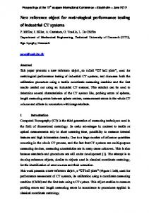
where zSubvjdenotes the number of edges connected t o vertex v j , which belongs t o the subgraph Qsub,and f ( x ) is 1if z is odd'and 0 if x is even. Figure 2 illustrates the two possible situations which
337
Authorized licensed use limited to: Danmarks Tekniske Informationscenter. Downloaded on July 01,2010 at 11:34:27 UTC from IEEE Xplore. Restrictions apply.
First consider the case of a changeable netlist. In a parallel graph the branch to traverse can be selected arbitrarily, the selection corresponds to choose a certain order of elements in the corresponding serial graph. In the case of a changeable netlist the problem can be formulated as to select an order in every serial subgraph which leads to the existency of a dual eulerpath ([6]). Consequently the algorithm starts in the parallel graph G P , in order to delay the binding of the order of the serial graph. To reduce the problem size all first-order subgraphs are reduced prior to the path tracing procedure. In G P odd parallel and all serial subgraphs are substituted with a single edge, while even parallel subgraphs are removed. In 9" all first order subgraphs are substituted with single edges. Even serial subgraphs corresponding to even parallel subgraphs in Q' are marked. The reduced graphs of B P and P are denoted RP and R" respectively. Two essential properties influence the solution; the choice of endpoints in a closed eulerpath, and a t which of the two possible vertices in RP t o resubstitute a even parallel subgraph. Other algorithms [2] seems t o make an arbitrary choice, but as shown in Figure 1, the choice may influence both area and electrical performance. Therefore a set of rules is proposed for an optimal choice of the endpoint in a closed path. In order of preference:
I I I I
._ I I
.a) Figure 2: Subgraph swap acceptance; a) f ( z S u b v ,=) f ( z S u b v j ) ; b) f ( ; s " b v 4 # J(;a"b%) A f(;\gaubv') = j(;\g'"*%). lead to swap acceptance. If no swap is accepted, then either the pin placement has t o be ignored (terminating the algorithm) or a diffusion gap has to be inserted. If no candidate is found, a series of swaps denoted as a multi-swap is performed. A multiswap is aimed at bringing e, and e,+l together. While the swap acceptance is identical with a normal swap, only subgraphs where Bsub n Ppoth = 8 are choosen as candidates, as the traced path would otherwise be changed during the swaps. Since it is possible to control the properties of the vertices while rearranging the graph, the algorithm can be used to change the endpoint vertices (i.e. the second type of acceptance) in order to either obtain dual eulerpaths if one does not exist, or to influence timing performance. Further the algorithm can be used to redistribute parasitic capacitances in order t o inprove timing performance, i.e. moving high valenced vertices further away from the output-terminal.
4.2
R u l e 1: Terminal-vertex. Prefer power-terminal to output-terminal. A terminal vertex (especially the power-terminal) will very likely require one routing track. Consequently the splitting of such a vertex will not influence the layout area. Further, the extra amount of diffusion area from the vertex splitting will have the least influence on the electrical performance when added to a power-terminal, while having significant influence when added to a output-terminal (the most sensitive vertex).
Rule 2: Internal-vertex. Always choose a multiple-vertex. If a single-vertex is chosen, cell height is increased since the splitting of a single-vertex causes two tracks t o be used because of power and output obstructions (cf. Figure 1). Also, the electrical performance is influenced as the parasitic capacitance is significantly increased.
No Constrainted Pin Placement
When no pin placement is given the objective is t o obtain an area optimal layout, taking into account timing aspects whenever possible.
Based upon the theorem:
Theorem 2 Having two dual graphs G P and G", a necessary condition for the ezistence of a dual eulerpath is that the same edges can be reached from endpoints in both G P and Gs.
MakeEulerPat hExist This algorithm is a special case of ChangeEulerPath, which performs function preserving changes on the graph in order t o achieve eulerpath existency. All subgraphs Gsub(v;,v j ) are possible candidates for a swap. The swap is only performed if the total number of odd valenced vertices are reduced, i.e. if
it is possible t o decide whether or not there is a chance of finding a dual eulerpath. If not, and the netlist is changeable, endpoints may be changed to meet this condition as described in
ChangeEulerPat h. The algorithm first finds all possible paths between the two endpoints in RP. This number is usually very limited and heuristics are used to remove unfeasible paths. In order to decide a t which of the possible vertices to resubstitute even parallel subgraphs, the dual graph (R')is traversed for each of the feasible paths (PP)from RP. When the next edge from PP cannot be reached directly, either a subgraph swap as described in ChangeEulerPath has to take place or one of the special marked edges has t o be used. Using one of the special marked edges corresponds to choose the vertex at which to resubstitute a even parallel subgraph in G P . If neither of the two situations leads to a solution, the next path is tried. In the case of a fixed netlist swaps are not allowed. Each path is completly traced and whenever the next edge cannot be
When all subgraphs have been examined, then if a t most two vertices have odd valence, the graph has been transformed into having an eulerpath.
FindEulerPath This algorithm finds a dual eulerpath in.the two dual graphs 4 P and 8" (index p for parallel and s for serial) if such exist. Depending on whether or not the netlist is fixed, the algorithm is allowed t o rearrange transistors in the two graphs in order to obtain an optimal solution.
338
Authorized licensed use limited to: Danmarks Tekniske Informationscenter. Downloaded on July 01,2010 at 11:34:27 UTC from IEEE Xplore. Restrictions apply.
reached directly or by a special marked edge, a gap is inserted. Finally the best solution is chosen. Once a solution has been found all first-order subgraphs can be resubstituted. If possible, high valenced vertices are placed away from the output vertex in order to improve performance.
5
Results
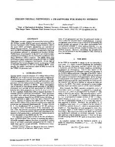
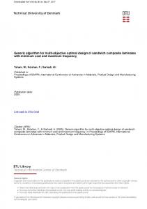
The algorithms described in this paper have been used to implement a cell compiler ( C E L L O ) working in the open experimental silicon compiler environment C A T O E ' [l]. C E L L O produces a symbolic layout, which is then transformed into mask layout by a compactor. Figure 3 shows C E L L O generated layout after compaction, together with the same circuit realized by two other methods [8] and [2]. In order to make this comparison, the same physical interpretation of the paths was used to generate the layouts for the different algorithms. Table 2 lists the area parameters for different layouts, which shows that the new approach presented in this paper performs better than [8] and [2]. Circuit C3 corresponds to the layouts of Figure 3. The first test chip generated by means of the C A T O E s y s t e m has been submitted for fabrication in a 2p n-well CMOS process'. Cell synthesis was performed using C E L L O . Figure 4 shows a section of ' the chip core.
Figure 4: Section of the first chip generated by the C A T O E system. The individual cells are generated from netlist descriptions by C E L L O .
6
Conclusion
A new approach for optimal layout generation of CMOS complex gates has been presented. This approach handles global constraints such as pin placement, given by a pre-place and route step, and timing considerations, by distinguishing between fixed and changeable netlists. Further, the approach has been used to implement a cell compiler C E L L O , which provides better solutions than previous algorithms.
........
References [l] A.C. Andersen, J. Madsen, J.R. Madsen and H. Pallisgaard, "A Dynamic Environment for VLSI Design Tools", NORSILC/NORCHIP seminar '88, Copenhagen 26-27 oclober, 1988.
b
[2] C.Y. Roger Chen and Cliff Yungchin Hou, "A New Layout Optimization Methodology for CMOS Complez Gates, " IEEE ICCA Dab'., pp.368-371, 1988. M. Lefebvre and C. Chan, "Optimal Ordering of Gate Signals in CMOS Complez Gates: A Heuristic Approach, internal paper, Dept. of Electronics, Ottawa, Canada, 1988.
......
C
d
J. Madsen, "The Impact of Gate Ordering on Circuit Delay," internal paper, Designcenter of Electronic Institute, Technical University of Denmark, El-LHT148, 1988.
Figure 3: Layout results using different algorithms; a) transistor circuit; b) [8];c) [2]; d) CELLO.
R.L. Maziasz and J.P. Hayes, "Layout Optimization of CMOS Functional Cells, 24th ACM/IEEE Design Automation Conference., pp.544-551, 1987. R. Nair, A. Bruss and J. Reif, "Linear Time Algorithms For Optimal CMOS Layout, VLSI: Algorithms and Architectures,., Bertollazi and Loccio Eds, North-Holland Pub., pp.327-338, 1985. Y. Shiraishi, J. Sakemi, M. Kutsuwadw, A. Tsukizoe and T. Satoh, "A High Packing Density Module Genemior for CMOS Logic Cells, c4
25th ACM/IEEE Design Automation Conference.,
pp.439-444, 1988.
Table 2: Width and height of layouts generated by 3 different algorithms .
T. Uehara and W.M. vancleemput, "Optimal Layout of CMOS Functional A m y s , " IEEE %ns. Computer Vo1.c-30, pp.305-312, May 1981.
'System developed by the CATOEgroup (Computer Aided Tool Engineering) at Electronics Institute. 'The chip i s produced under the Nordic brokerage service NORCHIP
S. Wimer, R.Y. Pinter and J.A. Feldman, "Optimal Chaining of CMOS %nsistors in a Funciional Cell," IEEE %ns. on CAD, Vol.CAD-6, no.5, pp.795-801, 1987.
339
Authorized licensed use limited to: Danmarks Tekniske Informationscenter. Downloaded on July 01,2010 at 11:34:27 UTC from IEEE Xplore. Restrictions apply.