A New Autoflight/FMS Interface: Guiding Design Principles Daniel J. Boorman Boeing Commercial Airplanes P.O. Box 3707 MC 20-89 Seattle, WA 98124-2207, USA
[email protected]
ABSTRACT
Human factors and flight operations experts have been studying crew performance issues with commercial transport autoflight and FMS interfaces for more than 20 years. A group at Boeing, in response to this work, has developed a new autoflight/FMS mode set and new interface design. In this paper, we discuss the drivers for the project, our method for generating autoflight modes, and design principles that shaped the interface prototype. Keywords
flight deck interface, automation, autoflight, flight management system, interface design, user-centered. INTRODUCTION
The introduction more than twenty years ago of digital autopilots, flight management systems (FMS) and electronic map displays brought pilots more and better information, decreased overall workload, and improved situation awareness. However, in terms of avionics architecture, the FMS was a lower integrity add-on to the autopilot system and was never integrated into a single system. Interface elements are distributed across the mode control panel (MCP), the FMS control display unit (CDU), and the primary flight display (PFD), which includes the flight mode annunciations (FMA). The new flight deck interfaces borrowed elements from past generations of aircraft. Autopilot modes such as HDG SEL (heading select), HDG HOLD (heading hold), and V/S (vertical speed) were passed along from earlier systems. New modes, like vertical navigation path and speed (VNAV PTH and VNAV SPD) were added to support the new flight management functions. Subsequently, as new requirements came along, such as GLS approaches, still more operating modes were added. The design process has been incremental, and although the benefits of new features have outweighed the penalties, increases in capability have been characterized by additional layers of FMS pages and complexity to the interface. As a result of this incremental evolution, the current interface is inevitably less than optimal for its functionality. Over the last 20+ years this interface has received considerable comment by numerous reviewers [e.g., 4, 5, 7, 11].
Randall J. Mumaw Boeing Commercial Airplanes P.O. Box 3707 MC 67-TC Seattle, WA 98124-2207, USA
[email protected]
Specifically, the following types of enhancements have been called for in the literature: • improve mode presentation and behavior. This applies particularly to VNAV, a family of modes, each of which may use varying altitude targets and flight path behaviors depending upon conditions. The complex rules behind VNAV and other modes sometimes make it difficult for pilots to anticipate aircraft flight path behavior. • improve feedback about whether tactical or strategic targets are being used. A tactical target (for purposes of this discussion) is one that is dialed into an MCP window by the flight crew; a strategic target is one that comes from the FMS flight plan. For example, VNAV PTH and sometimes VNAV SPD take altitude targets from the flight plan, but at other times VNAV SPD and VNAV ALT take targets from the MCP. (VNAV ALT may not display any target at all.) Boeing research shows that some pilots incorrectly assume that all VNAV modes always take altitude targets from the flight plan . • improve feedback about what aircraft flight path changes will occur next. Some mode transitions occur when a pilot takes an action. Other mode transitions occur when flight conditions trigger them (e.g., altitude capture). Although the FMA display on the PFD highlights changes with a transient green box, Boeing research [5] indicates that 3040% of these changes go undetected. Pilots typically have insufficient system knowledge to always anticipate the next behavior of the autoflight system. The result can be a flight crew surprised by an unexpected change in flight path. Several other specific issues have been raised, most of which are summarized by Wiener’s [10] questions “What’s it doing now?” and “What will it do next?”—that is, better predictability and transparency of the automated agent’s modes and behavior. Although the autoflight/FMS has been studied for two decades, the emphasis of these activities has been to describe human performance problems with the system rather than to design a comprehensive, practical solution. In 2001, Boeing human factors specialists and flight deck engineers, working in the flight deck research and development environment, undertook the development of a completely new autoflight/FMS system and interface. In
the following section, we discuss key issues that drove the new design. PROJECT DRIVERS AND PHILOSOPHIES
In addition to the enhancements called for in the literature (above), our project was motivated by two other important high-level drivers: - Reduced initial training. Approximately 40% of training time in a typical transition training course is taken up by autoflight and FMS. Our goal was to design a system that is so much simpler that training is cut by half or more. Proficiency and retention of knowledge should also be much better than with the current system. - Accommodate future changes in the air traffic management environment. Lacking a crystal ball, we listed many potential strategies that may be employed in the future and included all of them in the requirements. Any future function must be able to be added without adding new modes or mode complexity. We also formed some initial design philosophies that established our view of the optimum role of the flight crew with respect to the automated agent. These guiding principles would inform the subsequent design process. Level of Automated Control
There has been significant discussion in the literature regarding the appropriate level of control to be handed to the automation [e.g., 1]. At one extreme, the autoflight and FMS are given full authority, and the flight crew is relegated to monitoring the automation’s execution. At the other extreme, the FMS only stores a fight plan for reference by the flight crew, and it is up to the crew to initiate each flight path change (a climb, an airspeed decrease, etc.) as it comes to the top of the queue [8]. Current flight decks are near the first extreme, although they are inconsistent across axes (lateral automation has full authority, vertical authority is limited by the altitude window setting). The fact that the flight crew can intervene and give tactical commands (single targets to be used for an indefinite period) makes the current system less extreme. It is appealing to pursue a strategy of keeping the flight crew highly engaged by assigning them the task of initiating all flight path changes. However, in high workload situations this division of duties may not provide acceptable support to the flight crew. Furthermore, we judged that pilots would not accept being given the busywork of routine heading changes. A critical element in supporting crew engagement in current and upcoming flight path control is the feedback (information) the automation gives. In fact, we believe that the complaints levied against the current designs have more to do with the lack of feedback about automation actions than they do with the level of control given to the automation. With the current interface pilots must collect and correctly integrate the available information, which is
dispersed across several displays. In some cases, automation state information is not displayed anywhere. The strategy we settled on was to provide exceptionally clear transparency and feedback to the pilot, delivered graphically in the context of navigation displays (vertical as well as lateral), and to give full authority to the automation to execute the flight plan (consistent across all three axes). What is a Mode?
The current set of autoflight modes is large and has expanded over the years; a typical transport may have approximately 25 thrust, lateral and vertical modes. The mode titles (e.g. VNAV PTH) are non-descriptive codes that indicate an automation system state with a variety of potential behaviors and complex rules to determine which behavior will occur. The pilot’s task, which has proved difficult, is to remember and correctly apply the rules for the current mode. Also, the current set of modes is very much influenced by the system architecture. For example, THR REF is an autothrottle mode indicating full thrust while in a VNAV climb mode, while THR indicates the same autothrottle behavior while in a FLCH climb mode. The difference only has to do with which avionics box is sending the thrust command: the autopilot or the FMS. We decided to replace the modes with indications directly related to flight path behavior (e.g., Climb, Left Turn), and not confuse mode organization with avionics architecture. The final philosophical issue with modes was whether they should be mapped directly to ATC clearance language. Riley (2001) developed an approach called Cockpit Control Language (CCL) in which mode selection involves word matching to the ATC clearance. This approach theoretically allows a pilot to select a correct mode based only on the words contained in the clearance and a familiarity with the interface, with no additional cognitive steps. The additional step required by other systems has been described in Sherry et al. [9] as the “reformulate” step, in which the pilot interprets the clearance so as to understand the desired airplane flight path behavior, then maps the desired behavior to the available functions in the autoflight interface. We believe that the reformulate step is important to preserve because the flight crew must understand the desired flight path behavior in order to monitor airplane response. Further, the CCL approach requires an excessive number of modes to cover all possible clearances. In summary, we elected to create a new type of mode that was directly descriptive of flight path behavior, was not complicated by avionics architecture, and was not constrained to exactly matching ATC clearance language. Further definition of the new modes would result from a task analysis, described later in this paper. Attain a Waypoint Constraint, Not a Path
A principle of automation design that we have found to be crucial to support effective training and operational use is to ensure that the automated method is conceptually analogous to the alternative manual method used by pilots [2]. A prime
example of divergence from the manual method is the FMC path descent mode used on most commercial transports, which has been extensively commented upon in the literature [e.g., 4]. Currently, on descent, a theoretical idle descent path is calculated by the FMS, pitch is used to control the airplane to the descent path, and airspeed is allowed to vary. (This is much different than the manual method typically used in which a pilot reduces thrust to idle and uses pitch to control to an airspeed target.) If the airplane departs the path (typically, held above the path by ATC), the FMS displays the vertical deviation of the airplane relative to the path. Pilots are trained to recapture the flight path from above. We believe that this approach overemphasizes the importance of the FMS descent path, which is meaningless after the airplane has left it. The interface needs to focus control and feedback on the waypoint-altitude constraint that is the criterion for a successful descent. The new modes are analogous to the manual method. They allow descents to be flown with airspeed controlled by pitch, and rate of descent controlled by thrust and drag. The new interface includes tools oriented around ability to achieve the constraints, not oriented around recapturing a descent path. For future operations when a tightly controlled vertical “tunnel” may be required, the path capability is retained; but otherwise the new modes abolish the notion of an idle descent path. Full Mission Coverage
To achieve our goal of greatly reduced initial training, we knew the system must be vastly simpler than today’s systems. Given the entire domain of tasks in which airplane path is guided or controlled by automation (including future taxi guidance), if a solution was found that addressed only a portion of the domain, and old methods were used for the remaining portion, simplicity could not be achieved. For example, if up-and-away modes were all simplified, but final approach, landing and go-around were handled by existing modes, the pilot’s mental model of the system would continue to be complicated by inconsistencies due to the layering of old and new, and the pilot’s use of the system would be more complicated by the unnecessary mode transitions at high-workload flight phases (just before
landing or just after takeoff or go-around). We found that it is a “law” of achieving the benefits of a simplified design, that the entire domain must be included in the redesign. In the new design, approach, landing, go-around and even taxi guidance use the same modes and interfaces as up-andaway flight, resulting in only seven modes to cover the entire domain and providing an extreme level of simplicity and consistency. Don’t Make Infrequent Tasks Different
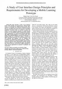
Particular difficulty can be observed in training, as well as in reports of problems in line operations, with tasks that are infrequently performed. Designers are careful to provide very simple and accessible interfaces for frequently performed tasks, but infrequent tasks are sometimes supported with non-standard interfaces with less direct access and unique procedures. And these infrequent tasks are sometimes performed under highly stressful non-normal conditions. For example, an engine-out drift down is rarely accomplished, and the current interface requires the flight crew to execute a precise sequence of actions to determine and set the right altitude target and engage the correct FMS sub-mode. We built a frequency-of-use mechanism into the task organization phase to ensure that all infrequent tasks would be handled by interfaces and procedures that were familiar to the pilot because of daily use. The new interface design includes drift down as a minor submode of a normal descent, and the drift down mode prompt is displayed full-time on the vertical MCP window for familiar and quick access. See the vertical (center) window in Figure 1. METHOD TO GENERATE A NEW MODE SET
We chose to start from scratch, using a comprehensive task list, which included several hundred aviate and navigate tasks that need to be managed by autoflight/FMS. Aviate tasks focused on a single pilot control goal. Navigate tasks had goals related to geographic fixes, the flight vertical profile or time. Navigate tasks could each be broken down into a series of aviate tasks. A key strategy for the new mode set was to ensure that infrequently accomplished tasks would be supported by familiar procedures, controls and indications.
Figure 1. Re-designed MCP with lateral, vertical and airspeed axes all linked to the flight plan
Figure 2. Initial Task Organization
To achieve this, each task in the task list was categorized as commonly accomplished, occasionally accomplished, or rarely accomplished. Figure 2 shows notionally how tasks with like characteristics were organized into groups, with a bias applied to ensure that all rarely accomplished tasks were grouped with commonly accomplished tasks so that common interface elements could be developed to support both kinds of tasks.
The pilot selects the basic mode as well as the performance details, so s/he is fully cognizant of the commanded behavior. System feedback clearly shows both the basic mode and the performance details so both pilots are aware of the system state and expected behavior. Figure 4 shows how the tasks align with the basic mode and mode performance details.
Figure 3. Example Task Grouping
Figure 3 is an example of one of the groupings from Figure 2. The set of similar tasks in the top row all fit in the category of “speed on elevator descents with varying performance targets, gains and thrust settings.” For reference, shown in the bottom row are a typical set of modes from a current airplane used to accomplish each task. All tasks were sorted in a similar manner, and the patterns that formed began to suggest a mode implementation that was compatible with the philosophies. The mode concept that emerged for the new autoflight/FMS system was a building block approach which begins with a simple, basic mode, such as Descend, then adds explicit performance details.
Figure 4. Building Block Approach to Mode Structure
As we moved through the full set of tasks, a new (and much smaller) set of modes emerged that was simple (small number of rules for each mode) and represented a complete integration between tactical (autopilot/MCP) and strategic (FMS) pilot goals. The new modes also removed phase of flight logic differences, and unnecessary differences between takeoff/approach/go-around operations and up-andaway operations. The new mode set is hierarchical with three levels: - At the top is the system operating state. The system is either “linked” to flight plan targets, or “unlinked,” using targets input by the pilot through the MCP.
- In the middle are the basic modes, which directly and specifically describe flight path control, for example L Turn, R Turn, Track, Climb, Descend. The same modes are used regardless of whether the system is in linked or unlinked operation.
window value and in other modes and conditions it will fly through it.
- At the bottom are performance details like a low-gain climb maneuver for passenger comfort, or a drift down sub-mode of the descent mode. The new mode set has seven basic modes and four submodes covering the lateral and vertical axes (speed/thrust modes have been eliminated), as compared to approximately 25 modes on current systems. Until this point, we had avoided specifying any requirements that would constrain the input controls in any way. We were careful to fully understand the modes and the expected system behaviors before any controls were designed. Next we were ready to specify the interface.
Figure 5. Lateral window in linked operation, with Preview line
INTERFACE DESIGN PRINCIPLES
In this section, we describe the purpose of several new interface features and illustrate how they can improve task performance. Clearly Distinguish between Linked and Unlinked
As we mentioned in an earlier section, pilots can be confused by which targets they are using and whether they are operating from the FMS flight plan or from tactical (MCP) targets. This is a critical distinction, and confusion can lead to inadvertent deviations from the flight plan. The new interface makes this distinction salient to ensure that flight crews understand the origins of autoflight targets. Figures 5 and 6 show the distinction between unlinked and linked operation. In linked operation (Figure 5), the NOW and NEXT lines are the top two lines of each window. The targets in both lines come from the flight plan (“FP”). The NEXT line shows the next lateral mode and target. In unlinked operation (Figure 6), the NOW line is still at the top of the window, but there is a jagged line below it to represent the disconnect from the FMS flight plan. The top line, in this case a right turn to a heading of 160, is a tactical target that will be used indefinitely. The flight crew needs to take action to link the airplane back to the flight plan (if they desire to continue with it). On the second line in Figure 6, below the jagged line, there is a button that re-links the airplane to the flight plan. Thus, flight crews have multiple cues regarding the source of the current target. Provide a Preview Line
The current MCP has a single window for each of airspeed, heading and altitude. Each of these three windows can be used for several purposes. The altitude window, especially, has multiple roles: in VNAV it is used to set the most recent altitude clearance which may or may not be the next leveloff altitude; in FLCH it is an actual climb or descent target; and in ALT (after pushing the Altitude Hold switch), the window value has no relevance to system operation at all. In some pitch modes the airplane will level off at the altitude
Figure 6. Lateral window in unlinked operation
In current airplanes, the three MCP windows behave in different ways. For example, the value dialed into the airspeed window is the current airspeed target, although the window may also be blank; the value dialed into the heading window is the current target only in HDG SEL mode. In all other lateral modes (LNAV, HDG HOLD, etc.) the heading window is not the current commanded value and is only used to set a bug on the displays. We decided to explicitly indicate these different meanings in each window and to increase consistency in window behavior. The most significant change is to provide a preview line that allows the pilot to build the next command and receive feedback that it is correct before making it the current command. The preview line appears at the bottom of each window when the tactical selector is rotated (Figure 5), and contains a “sense” of the command (L or R turn, Climb or Descent), “units” (heading or track, local altitude or flight level, IAS or Mach), and the commanded value. The preview line allows the flight crew to record an ATC cleared heading, altitude or airspeed and delay acting upon it if they choose to. With a single push on the tactical selector, the command becomes the current target (Figure 6). Also, when a tactical ATC clearance is datalinked to the airplane, the preview line displays the datalinked value until the crew confirms it with a single button push. One difference between this approach and the current designs is that, with the new interface, the flight crew never changes the MCP value that is the current commanded
value. A command is built for preview and then deliberately moved to the active command area. A Target for Every Mode: What’s it Doing Now?
With many current flight decks, autoflight modes are displayed without the current target (airspeed, heading, altitude). The target is either displayed elsewhere or sometimes not displayed at all. The flight crew must deal with these inconsistencies and find or deduce the target. We have kept modes and targets closely paired to ensure that the command state of the automation is clearly and completely communicated to the flight crew. Figure 1 shows the three MCP windows: lateral, vertical, and airspeed. The top line of each window is the current command. The mode title (Heading) is on the left and the target (129) is on the right. Lateral targets can be a heading or track, and a waypoint if applicable. Vertical targets are altitudes, and airspeed targets are knots or Mach number. Regardless of whether the targets were entered by the pilot through the MCP or, in linked operation, came from the FMS, the upper right corner always contains the current target. The airplane never “flies through” the target. This consistency makes training easy and should reduce errors in flight.
To realize the benefits of the simplified system, its features cannot be incrementally added to existing systems but must replace them entirely. Development and validation of the new design will continue until it is ready for full implementation on a flight deck. REFERENCES
1.
Billings, C.E. (1997). Aviation automation: The search for a human-centered approach. Mahwah, NJ: Lawrence Erlbaum.
2.
Boorman, D. J. (2000). Reducing flight crew errors and minimizing new error modes with electronic checklists. Proceedings of the International Conference on Human-Computer Interaction in Aeronautics, 57-63. Toulouse: Cepadues-Editions.
3.
Boy, G.A. (1998). Cognitive Function Analysis. Stamford, CT: Ablex Publishing Corp.
4.
Federal Aviation Administration (1996). FAA human factors team report on: The interfaces between flightcrews and modern flight deck systems. Washington, DC: FAA.
5.
Mumaw, R.J., Sarter, N., Wickens, C., Kimball, S., Nikolic, M., Marsh, R., Xu, W., & Xu, X. (2000). Analysis of pilots’ monitoring and performance on highly automated flight decks. (Final Project Report: NASA Ames Contract NAS2-99074). Seattle, WA: Boeing Commercial Aviation.
6.
Riley, V. (2001). A new language for pilot interfaces. Ergonomics in Design, 9(2), 21-26.
7.
Sarter, N.B. & Woods, D.D. (1995). How in the world did we ever get into that mode? Mode error and awareness in supervisory control. Human Factors, 37(1), 5-19.
8.
Schutte, P.C. (1999). Complemation: An alternative to automation. Journal of Information Technology Impact, 1(3), 113-118.
9.
Sherry, L., Polson, P., Feary, M., & Palmer, E. (2002) When does the MCDU interface work well? Lessons learned for the design of new flightdeck user-interfaces. S. Chatty, J. Hansman, & G. Boy (Eds.) Proceedings of HCI-Aero-2002, International Conference on Human Computer Interaction in Aeronautics. (Pp. 180-185) Menlo Park: AAAI Press.
Support Look-Ahead: What Will it Do Next?
Another common question in discussions of flight deck automation is “What will it do next?” The pilot’s ability to anticipate upcoming mode transitions is heavily dependent upon their knowledge of mode rules, and their ability to find the supporting data, which is dispersed across several displays. In linked operation, the next target comes from the FMS flight plan. When the new interface is in linked operation, the next mode and target are clearly displayed for each axis on the second line of the respective MCP window (see Figure 1). In unlinked operation, targets are set by the pilot and do not change, so there is no “next” behavior. In this case, the interface indicates it is unlinked and removes the “next” line (see Figure 6). CONCLUSION
Through these new design features, we have strived to reduce the procedural knowledge required to use the interface. The set of rules that prescribe interactions are quite consistent across like functions (e.g., the three windows) and the set of rules for each window is smaller. By greatly reducing the procedural knowledge required, we can reduce time to learn and improve retention. A prototype of the system has been used to conduct cognitive usability and training knowledge analyses. User testing is underway with pilot subjects.
10. Wiener, E.L. (1989). Human factors and advanced technology (glass cockpit) transport aircraft. (TR 177528). Moffett Field, CA: NASA-Ames Research Center. 11. Wiener, E.L., & Curry, R.E. (1980). Flight-deck automation: Promises and problems (NASA Tech. Mem. 81206). Moffett Field, CA: NASA-Ames Research Center.