network architecture for delivering broadband services to fast moving users (e.g. in trains). We specifically ... tunnel setup mechanisms and to prove that fast Ethernet recovery is feasible by extending the existing .... responsible for the reliable transport of data between AGWs and SGWs. ..... The commuter's laptop will obtain.
INTERNATIONAL JOURNAL OF COMMUNICATION SYSTEMS Int. J. Commun. Syst. 2000; 00:1–6 Prepared using dacauth.cls [Version: 2002/09/18 v1.01]
A New Carrier Grade Aggregation Network Model for Delivering Broadband Services to Fast Moving Users F. De Greve∗ , F. Van Quickenborne, F. De Turck∗ , I. Moerman, P. Demeester Ghent University - IBBT - IMEC Department of Information Technology, Gaston Crommenlaan 8 - bus 201, B-9050 Gent, Belgium
SUMMARY In this article, we present the research challenges that are associated with designing a cost-effective network architecture for delivering broadband services to fast moving users (e.g. in trains). We specifically extended the standard Switched Ethernet technology towards a truly Carrier Grade network solution for fast moving users. Prototype implementations allow us to evaluate dynamic tunnel setup mechanisms and to prove that fast Ethernet recovery is feasible by extending the existing spanning tree mechanisms. For architectures with multiple spanning trees the problem rises how the spanning trees have to be configured. Therefore, we propose time-efficient algorithms which solve the problem of aggregating paths into a minimal set of spanning trees. In the performance evaluation section, we compare vulnerable centralized backup systems to systems relying on distributed spanning tree-based recovery and it is shown that the former require more spanning tree instances to be configured than the latter for the same set of backup paths. The presented methods and results show that Ethernet technologies are well suited for building flexible and robust network solutions that c 2000 John Wiley & Sons, Ltd. can support fast moving users. Copyright ° key words:
mobility management; spanning trees; network recovery
1. Introduction 1.1. Motivation With the currently emerging trials and early-commercial solutions for internet solutions on the train, it is a matter of time before best-effort internet on the train becomes a reality. However, the challenge current telecom operators are facing is to deliver multimedia applications such as content delivery, video phoning and on-line gaming- which are generally characterized by high bandwidth and low latencies requirements - to users in fast moving vehicles. This lack of broadband services in vehicles such as trains, busses and vessels is stated in [1]. There is however no consensus on a widely deployed platform and different technologies can be used to realize the wireless connection: (i) cellular techniques, (ii) satellite based solutions
∗ Correspondence
to: Department of Information Technology, Gaston Crommenlaan 8 - bus 201, B-9050 Gent,
Belgium
c 2000 John Wiley & Sons, Ltd. Copyright °
Received ? Revised ?
2
F. DE GREVE
and (iii) Wifi/WiMax-based solutions. Currently a lot trials are deploying hybrid solutions in order to have maximal coverage: e.g. WiFi access when the vehicle is in the vicinity of a hotspot and GPRS (General Packet Radio Service) access throughout the rest of the trip is studied in [2]. The first range of solutions include wireless connections via existing cellular techniques such as GPRS , UMTS (Universal Mobile Telecommunications System) or HSDPA (High-Speed Downlink Packet Access) [3]. While the data rates for cellular solutions are increasing, they cannot compete with the bandwidths currently obtainable by Wifi/WiMaxbased solutions. Solutions based on satellite communication systems are currently the dominant player on the market for delivering internet on the train [4, 5]. However, on-roof antenna architectures with WiFi/WiMax base stations located near the railroad track are recently gaining interest [6, 7]. While satellite solutions are clearly advantageous in desolate areas, satellite signals cannot reach some places: e.g. in tunnels, in subways, in urban areas with high buildings or in steep valleys. Moreover, satellite solutions suffer from lack of uplink bit rates and will always suffer from high end-to-end delays which incorporate inescapably twice the propagation time between earth and satellite. This makes it impossible to deliver interactive real-time services. The WiFi/WiMax networks however can enable real-time seamless services in small cell infrastructures (i.e. micro-cellular networks) due to their ability to offer higher bandwidths. This requires dense installation of wireless base stations along the railroad track which need to transport the traffic from the vehicles to the fixed networks of service providers. However, current fixed aggregation networks are not optimally designed to cope with fast moving users and no mechanism is supported to maintain QoS guarantees for the admitted connections during the entire journey of the moving users. Therefore, an advanced dynamic traffic engineering problem has to be examined which can be described as follows: how to set up a dynamic path between the gateways in an aggregation network to meet the traffic demand of a request while achieving low congestion and optimizing the utilization of the network resources.
Layer 3 SGW
Service Provider A
Service Providers
Service Provider B
SGW AGW
AGW Supports IEEE 802.1s: Multiple Spanning Trees
Ethernet Aggregation Network
AGW
50m – 1 km
SGW: Service GateWay AGW: Access GateWay
50m – 1 km
Wifi – IEEE 802.11 or WiMax – IEEE 802.16
One antenna per carriage
Wifi – 802.11
Wireless/Wired Access Network
On-board router
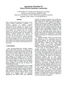
Figure 1. Schematic representation of the network architecture - specifically designed to cope with the requirements of train passengers.
c 2000 John Wiley & Sons, Ltd. Copyright ° Prepared using dacauth.cls
Int. J. Commun. Syst. 2000; 00:1–6
A NEW C.G. AGGR. NETW. M. FOR DELIVERING BR. SERV. TO FAST MOVING USERS
3
This requires not only a fast and robust tunnel setup mechanism to provide connectivity but also an associated admission control to maintain QoS guarantees. The network architecture is represented in Fig. 1 and was introduced in [8]. The problem of developing a broadband network for supporting fast moving users can be split in three sub-problems, the development of (i) the aggregation network, (ii) the access network and (iii) the internal train network. While the train passengers are connected to the internal WiFi train network via an on-board wireless router, the train carriages remain connected to the closest wireless base station near the railroad track. The distance between the track-side base stations is typically in the range of hundreds of meters (in case of Wifi) or in the range of kilometers (in case of WiMax). In any case base stations are grouped in access networks and the connections between access networks and the aggregation network are realized via Access Gateways (AGWs). At the other end, the aggregation network is connected to the service providers’ networks with Service Gateway (SGWs). The aggregation network itself is responsible for the reliable transport of data between AGWs and SGWs. This paper will focus on the design of the aggregation network part. As indicated on the figure the target network technology for the aggregation network is Switched Ethernet. This will be detailed in Section 2. 1.2. Related work While this paper focusses on the development of the aggregation network, a lot of research effort has already been devoted to the other subproblems: design of the access network [9], seamless handover improvements in IEEE 802.11 infrastructure networks [10] and design of the internal train network [11]. At the application level [12] aims at improving the behavior of moving users which are only occasionally connected with a wireless access point along the road (= islands of connectivity). Other areas of research try to improve handovers between different wireless technologies [13] or to enable handover of application sessions between different end user terminals [14]. On one hand, the aspect of taking the moving user’s performance into account is being addressed in the ongoing standardization processes for the mobile extensions of Wifi and WiMax [15]. On the other hand, a platform for the management and configuration of dynamic tunnels in a fixed network has been presented in the IETF drafts for MPLS-TE [16]. However, the combination of dynamic traffic engineering for fast moving users has not been studied before. We will present novel Layer 2 techniques for designing and realizing the fixed-wireless convergence in an aggregation network environment. As illustrated on Figure 1, the architecture’s forwarding technology will be Switched Ethernet which can use the legacy IEEE 802.1D Spanning Tree Protocol (STP) [17] to maintain a loop free spanning tree topology. Elimination of loops is crucial for correct Ethernet functionality and in case of failures a new spanning tree topology will be configured. Enhancement of the recovery times has been addressed by introduction of the IEEE 802.1w Rapid Spanning Tree Protocol (RSTP) [18]. Finally, IEEE 802.1s Multiple Spanning Tree Protocol (MSTP) [19] was introduced which maintains multiple trees instead of a single tree. Because all links can now be used in the network (instead of at most N-1 links in an network of N nodes), the bandwidth efficiency of IEEE 802.1D/w Ethernet networks is improved. However, spanning trees are still rather seen as a restricting feature for the Carrier Grade possibilities of Ethernet. Indeed, spanning tree recovery is still quite slow, certainly if you compare it to SONET/SDH recovery. c 2000 John Wiley & Sons, Ltd. Copyright ° Prepared using dacauth.cls
Int. J. Commun. Syst. 2000; 00:1–6
4
F. DE GREVE
Another relevant research topic in MSTP-based networks is the spanning tree assignment. Spanning trees are widely studied in diverse scientific disciplines [20, 21] and are well known in the domain of telecommunication networks. Whether spanning trees are used for realizing resource-efficient transport of multi-cast traffic [22] or for other optimization objectives, these problems are mainly focussed on finding trees which satisfy the constraints and on selecting a single best tree which fits certain minimization criteria. However, in this work we present the problem of identifying an optimal sub-set from the complete set of spanning trees comprised in a graph. This is a significant more complex problem than finding a single best tree. In [23] a heuristical approach is already presented for the problem of mapping a predefined set of paths on a minimal set of spanning trees. 1.3. Contribution In this work, we present a network architecture that delivers broadband services to the fast moving users. A global view is presented on the design approach which reveals the research challenges that are associated with designing a cost-effective and dynamic Ethernet network solution. We specifically extended the standard Switched Ethernet technology towards a truly flexible and robust network solution for fast moving users. Based on performance analysis of prototype implementations, we thoroughly evaluated the dynamic tunnel setup mechanism and we proved that fast Ethernet recovery is feasible by extending the existing spanning tree mechanisms. For the planning phase we present algorithms which efficiently solve the problem of aggregating paths into a minimal set of spanning trees. These algorithms are compared with existing path aggregation methods for various network scenarios and for recovery scenarios with predefined backup paths.
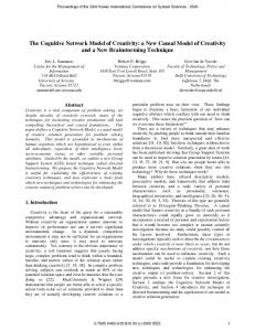
2. Cost-effective Ethernet Design for Delivering Broadband Traffic to Fast Moving Users First of all, we have to choose a networking technology for the aggregation network. Fully meshed IP routers could be installed, possibly extended with MPLS capabilities for enabling connection oriented traffic control and guaranteeing the QoS constraints. However on the other hand, one could consider a cheaper solution with Ethernet switches. We consider the Switched Ethernet technology to be the most appropriate choice because of different reasons: simplicity, auto-configuration, cost effectiveness and bandwidth flexibility. However, existing tunnel mechanisms for MPLS/IP networks are not easily portable to Switched Ethernet networks. Tunnel mechanisms such as CR-LDP (Constraint-based Label Distribution Protocol) [24] are mechanisms in which the protocol messages contain the explicit set of nodes along the entire path. This tunnel mechanism could be implemented because Ethernet switches are aware of their neighbour switches: however the explicitly defined routes would still suffer from the fact that packets should remain on a single spanning tree instance in order to avoid data loops at all times. Furthermore, tunnel mechanisms, like LDP (Label Distribution Protocol) and RSVP (ReSerVation Protocol) [25] which make use of IP routing tables are not well suited because the entries of the Forwarding Databases are regularly deleted: explicitly flushed or timed out. It is obvious that these problems can only be resolved by a protocol with broadcasting capabilities. Figure 2 presents our approach for designing and managing the aggregation network for fast c 2000 John Wiley & Sons, Ltd. Copyright ° Prepared using dacauth.cls
Int. J. Commun. Syst. 2000; 00:1–6
A NEW C.G. AGGR. NETW. M. FOR DELIVERING BR. SERV. TO FAST MOVING USERS
Offline operations
5
Online operations Location awareness at run-time Current train access point location
Train schedules Train-related information
Sydney – Canberra: 08u00 – 24-00 Melbourne – Adelaide: 07u30 – 11u58 Cairns – Alice Spring: 22u50 – 08u30 Hobart – Perth: 08u02 – 05u43 Brisbane – Wollongong: 17u52 – 21u24
or
input
input MCFA
Planning Tool for calculating link and node capacities Centralized flow assignment techniques
GPS
input Management system
CFA
Online path calculation Motion-aware Capacity Capacity Capacity Capacity Capacity Assignment Capacity Assignment Capacity Assignment Assignment Assignment Flow Assignment Assignment Assignment
Flow Assignment time
Results in
Set of required paths Ethernet deployment
Minimum set of spanning trees
Realised in
Service realisation
ST config
Managed Ethernet Network
Figure 2. Approach for designing cost-effective Ethernet networks that supports fast moving users.
moving users. The top level contains train-related information describing the highly dynamic traffic conditions. The second level contains centralized methods for planning and managing the network. The bottom level describes the deployment and realisation in a Layer 2 Ethernet data plane. In order to optimize the network resources and planning of network equipment we presented in previous work theoretical models to solve the Motion-aware Capacity Flow Assignment (MCFA) problem [26]. These models calculate the network equipment that needs to be installed, where to place the fibers between the network nodes, how to set up and adjust the AGW-SGW tunnels and how to route the traffic flows at every moment in time. This planning tool takes into account that trains can be delayed or that end-to-end delay variations between tunnels have to be minimised in order to avoid packet reordering or packet loss during hand-over. Apart from this off-line planning tool we developed an on-line management system that is responsible for the on-time configuration of the network. Trains will use a heart beat mechanism to indicate their current point of attachment. More detailed location information such as GPS information could be used on top of this to determine the optimal handoff moment but it remains an open question to which extent the increased complexity could be justified with a proportionally increased performance gain. These topics are not discussed in this paper and for further details we refer to our previous work [27]. In this article we will focus on the bottom level, the Ethernet deployment aspects: the protocol design, Ethernet extensions and their performance evaluation in test bed environment. We will also develop path aggregation c 2000 John Wiley & Sons, Ltd. Copyright ° Prepared using dacauth.cls
Int. J. Commun. Syst. 2000; 00:1–6
6
F. DE GREVE
techniques for solving the problem of mapping paths on a minimal set of spanning trees. This is a relevant problem in standard Multiple Spanning Tree networks where the number of spanning trees is defined off-line by the network management.
3. Deployment of Ethernet Aggregation Networks 3.1. Continuous connectivity and dynamic reservations The WiMax-based FAMOUS (= FAst MOving USers) architecture is illustrated in Fig. 1. The network consists of standard QoS-aware Ethernet switches (IEEE 802.1s, IEEE 802.1q&p compliant) with separated hardware queues per QoS class. Because the network runs the Multiple Spanning Tree Protocol (MSTP) which maintains multiple trees instead of a single tree, the management system can make optimally use of all links (instead of N-1 links in a network of N nodes) in order to load balance the traffic over the different tree instances. At the network edges traffic will be VLAN-tagged: the VLAN tag will be uniquely assigned to a single spanning tree instance and will define the end-to-end path because every tree contains just one single path between every two nodes. For the upstream traffic this tagging will occur in the AGW where train users are aggregated per train and per QoS class in order to avoid to have an entry for every individual user in the reservation database. For the downstream traffic tagging will occur in the SGW which is constantly updated with information about the current (and future) positions of the trains; every turn the location of the next hop gateway towards the moving users’ network gets updated. It is important to notice that Mobile IP can run on top of this architecture to enable handovers between different Ethernet domains. The connectivity in the aggregation network is achieved by setting up dynamic tunnels in the aggregation network between the AGWs and the SGW in which the aggregated traffic flows are mapped. Service guarantees can be assured by making on-time resource reservations. Data connections of fast moving users will be mapped on VLAN-based tunnels that are responsible for the delivery to the correct AGW in the aggregation network. The VLANs are fixed end-toend tunnels, automatically installed with GVRP (GARP VLAN Registration Protocol). It is important to notice that it is inefficient to dynamically change VLAN tunnels according to train movements in order to keep e.g. the train-VLAN mapping consistent for the entire Ethernet domain. The dynamic aspect is related to the location awareness and the on-time reservations. The management system maintains a database with train schedules and routes but it is not sufficient to reserve and release the necessary VLAN tunnels according to these schedules. Train delays can occur or additional trains may be added; this imply that the preferred tunnels are not known in advance but need to be calculated on-line. A centralized calculation module is preferred in order to determine the optimal routes and identify capacity bottlenecks in the network. Tunnel reservations are registered dynamically by the management system with knowledge of the current position of the trains. When reservations are no longer required, they are immediately released. In this way the system will guarantee that the current and the next hop tunnel are able to maintain the service level and that capacity bottlenecks are prevented. The Layer 2 reservations can be maintained by a centralized calculation module which keeps state of all reservations or with an on-line hop-by-hop reservation protocol. We prefer the second option in which case the management system only has to monitor the reservation c 2000 John Wiley & Sons, Ltd. Copyright ° Prepared using dacauth.cls
Int. J. Commun. Syst. 2000; 00:1–6
A NEW C.G. AGGR. NETW. M. FOR DELIVERING BR. SERV. TO FAST MOVING USERS
7
states. If train movement requests arrive at the management station, it suggests the best path for the future tunnel based on the on-line CFA (Capacity Flow Assignment) algorithm.
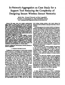
3.2. Addressing & tunnelling In Fig. 3 the network solution is presented for moving user communication and intra train communication services such as public address announcements or train lights control. Figure 3 illustrates that there is no need to unite carriages of the same train constitution into the same IP range. Each on-board router will receive a subnet address range (e.g. 187.168.74.0/26) from a central DHCP server: a subnet for the carriage’s internal WLAN (e.g. 187.168.74.0/25) and a subnet for local controllers (e.g. 187.168.74.128/25). The system is robust to carriage constitution changes: adding/removing carriages and uniting/splitting trains. We assume that every carriage has an on-roof antenna and associated on-board router but a similar architecture is valid when antennas are shared over multiple carriages. The commuter’s laptop will obtain an IP address from the DHCP server on the train (e.g. 187.168.74.12). All these IP addresses are fixed for the duration of the journey which means that train carriages are considered as moving Layer 3 networks. Mobile IP interaction is only triggered when you leave the Ethernet aggregation network. As is shown, the location of the moving Layer 3 networks is stored in the SGW. Because instead of individual users entire networks move, the size of this table is kept limited. Data traffic will be tunnelled through the aggregation network: this can be done by encapsulating the original packet with a new VLAN-tagged packet (MAC-in-MAC) or by VLAN stacking (Q-in-Q). Both methods will keep the network scalable but differ in the addresses learning at the core switches of the aggregation network. By using MAC-inMAC tunnelling at the AGW the MAC addresses of devices on trains or end user devices are concealed for the aggregation network which now only is aware of a limited set of nonmoving MAC addresses and the on-board router could be replaced by a Layer 2 switch. If
Dst IP address Tunnel MAC address
66.249.0.0/16
187.168.74.0 187.168.12.0
00:02:B3:D1:C3:69 00:50:BA:AB:C5:DD
Service Provider A
169.254.0.0 /16
Service Provider B SGW
VLAN tunnel
VLAN tunnel Ethernet Aggregation Network
00:02:B3:D1:C3:69
00:50:BA:AB:C5:DD
192.168.0.0/16 AGW
187.168.74.128/25
AGW
187.168.84.128/25
Local Controler
Local Controler
187.168.12.128/25 Local Controler
WiFi Network
WiFi Network
187.168.74.0/25
187.168.84.0/25
Global Controler
187.168.12.0/25
Figure 3. Layer 3 view of the MAC-in-MAC tunnelling network.
c 2000 John Wiley & Sons, Ltd. Copyright ° Prepared using dacauth.cls
Int. J. Commun. Syst. 2000; 00:1–6
8
F. DE GREVE
VLAN stacking is used, an on-board router still needs to be used to minimize the address explosion in the aggregation network’s forwarding databases and the aggregation network is aware of the MAC addresses of the moving on-board routers. The physical appearance of the tunnels as VLAN tunnels has advantages and disadvantages. The pros are mainly increased security, broadcast avoidance and possible high speed swapping techniques based on VLAN label lookup instead of MAC address lookup. Remind that the use of VLANs is anyway required in a multiple spanning tree architecture to select a specific tree. The contras are extra setup management overhead and extra overhead for spanning tree based recovery. The extra management overhead remains limited because VLAN paths remain fixed during operation and the setup can be performed off-line. The extra overhead for Spanning Tree based recovery is evaluated in Section 6.
4. Towards a Carrier Grade Switched Ethernet In the previous section, we presented how Layer 2 technologies can be aggregated in a system that can support fast moving users. However, in order to make a reliable, highly dynamic and QoS-guaranteed system standard Ethernet networks are not sufficient. The Quality of Service support provided by Ethernet is based on IEEE 802.1p traffic prioritization. This shared bandwidth service makes it difficult to deliver hard Service Level Agreements (SLAs). Due to the lack of a Layer 2 reservation system it is hard to guarantee bandwidth requirements. One of the strong features of the Ethernet technology is its auto-configuration and plug-andplay capability. One of the challenges is to extend the existing technology towards a managed Ethernet platform without sacrificing too much of the auto-configuration features. Another issue is the spanning tree performance which is still considered as a rather slow mechanism. In this section, we address a number of these issues. More specific, we present a dynamic tunnel setup mechanism with associated Layer 2 reservation mechanism and a fast and distributed Ethernet recovery mechanism. 4.1. Layer 2 protocol enhancements The Generic Attribute Registration Protocol (GARP), described in IEEE 802.1d, provides a generic attribute dissemination capability for bridged LANs. Two standardized GARP applications (described in IEEE 802.1q) exist: GARP Multicast Registration Protocol (GMRP) and GARP VLAN Registration Protocol (GVRP). GMRP allows group membership information to be distributed but we are interested in GVRP, which provides a mechanism for dynamic maintenance of the VLAN Active Filtering Databases and for propagating the information they contain, to other VLAN-aware bridges. Commercial developers have created GVRP implementations and most Ethernet switch vendors support GVRP but to our current knowledge there is no open source implementation for Linux available. 4.1.1. Automatic Tunnel Setup Mechanism Given the choice for Ethernet in order to design a low cost aggregation network, the usage of VLAN-based tunnels (e.g. instead of MPLS) is straightforward, knowing that most of the Ethernet switches already support VLANs. In the search for a new tunnel setup mechanism, we found that GARP-based protocols are providing all the necessary capabilities. Therefore, why develop a brand new protocol, if you c 2000 John Wiley & Sons, Ltd. Copyright ° Prepared using dacauth.cls
Int. J. Commun. Syst. 2000; 00:1–6
A NEW C.G. AGGR. NETW. M. FOR DELIVERING BR. SERV. TO FAST MOVING USERS
Switch A
Switch A
no overhead registrations
b: End result after triggering switch A
Switch A
Switch B
Switch B
Switch B
a: Result after triggering switch B
9
c: Optimal end result with scoped refresh
Figure 4. Scoped refresh extension.
can intelligently make use of a standardized Ethernet broadcasting protocol? GVRP removes the burden of manually installing and maintaining VLANs from the network administrators hands. The automatic VLAN registration is performed in a more consistent and reliable way compared to the laborious manual VLAN configuration on every switch in the network. GVRP not only reduces the chance of incorrect VLAN configurations but also makes the VLANs resilient to Layer 2 network failures because it works in conjunction with the spanning tree protocol (STP). After the spanning tree protocol has converged, the VLANs are automatically re-mapped to the new topology induced by the new spanning tree (ST). However, standard GVRP suffers from one big drawback. Consider the following access network: the network contains a single SGW and 2000 AGWs. The network devices are Ethernet switches supporting GVRP with VLAN Databases of 64 entries (most currently available switches do not support the whole range of VLANs) and one Ethernet switch with a VLAN Database of 2000 entries to connect to the SG. The exact amount of switches and the chosen topology are not relevant for the considered problem but in this legitimate situation, it is impossible to set up an individual VLAN pipe for every SGW-AGW pair with standard GVRP-based methods. GVRP distributes all the registered VLAN IDs to every switch in the network and produces a lot of overhead registrations that will flood the limited sized VLAN Databases. GVRP was namely never designed to set up point-to-point VLAN tunnels but the VLAN topologies would rather resemble a sub-tree of the ST topology. This VLAN Database depletion problem can be resolved by removing the overhead registrations and therefore we developed the ”Scoped Refresh” extension of GVRP. In Fig. 4, the GVRP operation to set up a tunnel between switches A and B is illustrated. Just like RSVP and LDP, a single GVRP run is responsible for setting up a single direction of the tunnel, meaning that a trigger to each end device is required to configure the entire tunnel. First, a single edge device is triggered and the VLAN ID is propagated towards the entire network (Fig. 4a). After triggering the other end device, the bidirectional VLAN path between A and B is established but the overhead registrations remain (Fig. 4b). For the GVRP extension, the desired end situation is shown in Fig. 4c. Every switch will detect individually the number of registrations for a specific VLAN value on its interfaces. If this number equals two, the switch is part of the VLAN tunnel and will issue de-registration messages on its non-registered interfaces for this VLAN value. If this number becomes lower c 2000 John Wiley & Sons, Ltd. Copyright ° Prepared using dacauth.cls
Int. J. Commun. Syst. 2000; 00:1–6
10
F. DE GREVE
than two, the switch is no longer part of the tunnel and will issue registration messages on its non-registered interfaces. In the system design we will assume that VLAN configurations never fail due to insufficient amount of VLAN databases. 4.1.2. Distribution of reservation parameters The GVRP resolved setting up a physical pointto-point tunnel but is still lacking means to reserve bandwidth and/or configure the switch hardware according to the QoS-related parameters associated with each tunnel. Instead of extending GVRP to support attribute types to propagate reservation parameters, a new GARP protocol is designed. This protocol is called ”GARP Reservation Parameters Registration Protocol” (G2RP). By separating the distribution of reservation parameters and VLAN IDs, G2RP remains independent of the applied tunnel setup mechanism (e.g. static VLAN entries). G2RP is designed according to the GARP standard. We will address the unresolved issues of the standard that are implementation specific. First of all, the G2RP application address needs to be defined. This address will be used as destination address in the Layer 2 header of the so called G2RP Protocol Data Units (PDUs). It is chosen from the range of GARP broadcast addresses: 01-80-C2-00-00-20 to 00-80-C2-00-00-2F. The first two addresses from the range are in use by the two existing GARP applications GMRP and GVRP [3]. We have chosen the first free address in the list: 01-80-C2-00-00-22. Secondly, the G2RP specific attribute type and values need to be defined. Only a single attribute type is required and the attribute value format is represented on Fig. 5 for the G2RP PDUs. The first field indicates the VLAN associated with the reservation parameters and the second field is a reservation session VLAN-ID
RSV-ID Reservation Parameters A
Reservation Parameters B
Figure 5. Attribute value format for G2RP Protocol Data Units (PDUs).
ID, followed by the two fields of reservation parameters, one field for each direction of the tunnel. These reservation parameters contain information such as the QoS class, bandwidth parameters, burst size and the size of the time sample window. G2RP allows a robust method for making reservations per VLAN and per QoS class. Existing reservations can be altered by distributing G2RP PDUs containing updated parameters for the same VLAN value and QoS class. A different RSV-ID is used to distinguish incoming PDUs with updated parameters from incoming PDUs due to the GARP refresh mechanism. After defining the G2RP semantics, the appropriate hardware operations have to be linked with registration and de-registration events. Basically, the switch hardware (bandwidth shapers, classifiers, queues, etc.) will be configured according to the registered parameters for the associated VLAN value and QoS class. Before any configuration takes place, G2RP will consult the admission control. Admission control is added to keep track of the existing bandwidth reservations. If at any point along the VLAN tunnel the available hardware resources are not sufficient to support a specific reservation, this reservation will fail and its PDUs wont be propagated in the switch. Finally, the GIP (= GARP Information Propagation) context is free to define. This context defines a subset of the ports of the switch, forming the active topology for the propagation of GARP messages. GMRP and GVRP are both using the active ST topology as GIP context. The GARP standard allows more complex active topologies depending of the instance of ST or VLAN ID. For the G2RP application, we linked the GIP context to the pre-established VLAN tunnel. This allows safe c 2000 John Wiley & Sons, Ltd. Copyright ° Prepared using dacauth.cls
Int. J. Commun. Syst. 2000; 00:1–6
A NEW C.G. AGGR. NETW. M. FOR DELIVERING BR. SERV. TO FAST MOVING USERS
Propgate G2RP PDUs
Switch A
Switch B
QoS 1
QoS 1
...
Reverse G2RP PDUs
QoS 0
QoS 0
VLAN tunnel
...
QoS 1
QoS 1
QoS 0
QoS 0
11
VLAN tunnel
No G2RP PDUs leave the VLAN context
Figure 6. G2RP message propagation.
broadcasting of reservation parameters in the associated VLAN tunnel. While the GIP context was previously fixed for all GARP applications, G2RP introduces a dynamic GIP context. For every incoming G2RP PDU the associated VLAN ID is identified and used for the propagation towards outgoing ports, which are member of the same VLAN. Just like GVRP, a single run of G2RP is responsible for configuring a single direction of the tunnel but in contrast to the GVRP, a G2RP reservation session can fail due to interference of the hop-by-hop admission control. Therefore, a closed loop design is preferred for G2RP. This is illustrated in Fig. 6. In contrast with GVRP, a single trigger is sufficient to configure the entire tunnel: at the opposite end of the VLAN tunnel (i.e. switch B), the G2RP PDUs are reversed and sent back to the originating end of the tunnel (i.e. switch A). G2RP PDUs will always follow the VLAN pipe, even in conditions of VLAN path reconfiguration. If at the originating switch the reversed PDUs do not arrive in time, the reservation session will have failed due to insufficient network resources. 4.2. Rapid recovery after failures 4.2.1. Failure recovery cycle of Ethernet In MSTP networks every tree instance - either the Internal Spanning Tree (IST) or either one of the Multiple Spanning Tree Instances (MSTIs) - is an RSTP instance. Therefore, MSTP recovery is identical to RSTP recovery. The recovery cycle starts not when a network impairment occurs but when the failure is detected. Therefore RSTP’s heart beat mechanism causes all the participating bridges to regularly send BPDU (Bridge Protocol Data Unit) packets out of their ports. BPDU packets are sent every Hello Time interval. If during 3 Hello Time intervals no BPDUs are received on a link, failure of the link or neighbour switch is assumed. For the standard Hello Time (= 2 sec) this implies a detection time between 4 and 6 sec. After failure detection, switches will initiate recovery by electing a new port that will be used as path to the root and by notifying neighbour switches of this change. This election process will propagate throughout the network until the connectivity is recovered. During the recovery operation, Topology Change Notification (TCN) messages are sent. The TCNs are flooded very quickly across the whole network and on receipt switches will flush the necessary MAC addresses. Failure convergence in RSTP is reached when the spanning tree connectivity is recovered and all out-dated MAC addresses are removed from the forwarding tables. The duration of the recovery operation itself is dependent on the type of failure and the size of the network: from 1 ms up to several tens of ms. c 2000 John Wiley & Sons, Ltd. Copyright ° Prepared using dacauth.cls
Int. J. Commun. Syst. 2000; 00:1–6
12
F. DE GREVE
4.2.2. Recovery enhancements for managed Ethernet networks A lot of research effort has been devoted to improving Ethernet recovery times. In [23] failure detection is notified by the switches itself to a centralized management system. This management system keeps pre-computed back-up paths for each source-destination pair. The spanning tree recovery is bypassed and the system will reroute the affected flows onto other spanning trees by changing the VLAN entries at the appropriate edge switches. This benefits optimally from the multiple source-destination paths that are available in a MSTP architecture and reduces the recovery time to 400-600ms. However, an expensive central management system is required, which should be duplicated to be failure resistent. Instead of adding a novel management component that deals with recovery, a distributed mechanism is proposed that maintains the plug-and-play feature of Ethernet. In a distributed system recovery times will be dependent on the network size (as opposed to a centralized system) but we will prove that fast recovery (order tens of milliseconds) in realistic sized networks is still possible. Having the recovery power centralized in a single location is a poor strategy, certainly if you have in mind that malicious attacks and nature disasters typically affect a whole network area instead of a single location.
The recovery times of standard RSTP take about 4 to 6 seconds and are clearly dominated by slow detection times. If this problem could be alleviated, there is no real restriction why connectivity could not be restored quickly after network failures. Therefore, the RSTP failure detection is bypassed by deploying another more bandwidth efficient heart beat mechanism that monitors the link status: Link Probe [28]. When we only want to monitor the link status, there is no need to send specific packets since any packet is fine to assert that the link is operational. The receiver module of Link Probe will reset the receive interval at the receiving side every time any packet is arrived. The send module of Link Probe will assure that every send interval at least one packet is transmitted on the link. The send module will monitor the outgoing packets; if a packet is sent during the send interval, the sender does not need to send a packet. This means that the send and receive interval can be reduced without sacrificing usable bandwidth. After detection recovery of connectivity is performed quickly but this operation is not sufficient to recover the data operation; as mentioned before out-dated MAC addresses need to be flushed. RSTP was designed to deal with detection times that are determined by its Hello Time. Because the faster Link Probe mechanism takes over, we payed special attention to the implementation of the RSTP flushing mechanism to clear all out-dated addresses as fast as possible. Otherwise flushing risks to be postponed for a single period of the Hello time. However, network recovery will cause VLAN tunnels to be rerouted. Before data connections can be resumed, dynamically configured VLANs have to reconfigure on their turn according to the new spanning tree topology. This reconfiguration time is minimized by slight modification of the GARP example code from the IEEE 802.1D standard. The functionality is not changed but otherwise reconfiguration would run the risk of being delayed for 10 seconds. The use of end-to-end VLAN tunnels has the benefit that temporal broadcasting of data packets after MAC flushing is always constrained inside the VLAN and doesn’t use up extra resources. Just like RSTP recovery GVRP reconfiguration is not dependent on protocol timers. This means that GVRP can be implemented in a way that changes propagate throughout the network as quickly as possible. The performance of the improved Ethernet recovery mechanism is evaluated in Section 6.3, both for the basic spanning tree operation and for dynamic recovery of VLAN tunnels and associated reservations. c 2000 John Wiley & Sons, Ltd. Copyright ° Prepared using dacauth.cls
Int. J. Commun. Syst. 2000; 00:1–6
A NEW C.G. AGGR. NETW. M. FOR DELIVERING BR. SERV. TO FAST MOVING USERS
13
5. Path Aggregation Technique for Calculating a Minimal Set of Spanning Tree Instances Deployment of routing schemes in Ethernet requires mapping of the required routes as calculated for the MCFA problem on VLANs and STIs (Spanning Tree Instances). The IEEE 802.1s standard does not specify any details of mapping VLANs on one or more STIs. The amount of VLANs that need to be configured is determined by the number of AGWs (Access Gateways) and the number of parallel paths to each AGW. Within an aggregation network scope, the amount of required VLANs will clearly remain under the VLAN upper limit (i.e. 4096 due to the 12-bit representation of VLAN labels). For the spanning tree assignment we present a path aggregation (PA) algorithm that forms a minimal set of STIs. We will compare its performance with a Random Assignment (RA) and with the PA heuristic [23] that tries to merge paths which share a common feature e.g. pair of edges. We refer to this method as the Shared Assignment (SA). Joining paths with shared features is a good idea but we will prove that this provides no absolute guarantees about obtaining a minimal set. For aggregation networks that support users that move along well-known routes, typically a lot of the paths will be sub-paths of other paths. With this knowledge, the idea is to aggregate those paths on the same spanning tree - Sub-path Assignment (SpA) - and it will be shown that this is in fact a more relevant condition for obtaining a minimal set. The pseudo-code of the SpA algorithm is presented in Algorithm 5.1. The performance of this heuristic is evaluated in Section 6.4 for different network scenarios.
Algorithm 5.1: Sub-path Assignment(ST Is) Set of all paths : Φ ← (p0 , ..., pm ) Φ ← order(Φ) comment: in descending order of path length Set of all path pairs : PP ← {(p0 , p1 ), ..., (pm−1 , pm )} Set of path pairs taking part of same STI : PPsame = ∅ Set of all spanning trees : T = ∅ while (∃{pk , pl } ∈ P P ) true comment: Sub-path substitution step Remove{p½ k , pl }fromPP. do if pk ⊆ pl Add {pl , pk } to PPsame . ½Remove pk from Φ. if pl ⊆ pk Add {pk , pl } to PPsame . Remove pl from Φ. while(∃p ∈ Φ) true Remove p from Φ if (∃t ∈ T :checkloop(p, t) == true ) then Merge p with t and do ∀ q with (p, q) ∈ PPsame : Merge q with t. else Add p to new tree in T and ∀ q with (p, q) ∈ PPsame : Merge q with new tree.
c 2000 John Wiley & Sons, Ltd. Copyright ° Prepared using dacauth.cls
Int. J. Commun. Syst. 2000; 00:1–6
14
F. DE GREVE
A tree is represented as a loop-free subset of paths from Φ which are part of the tree. We call this the Path Composition representation, which is actually quite similar as the Predecessor representation [29]. Paths are expressed as an ordered vector of nodes. Additionally sets of nodes are maintained which form disconnected subtrees - part of the actual tree - in order to enable faster loop checks. Intermediate tree solutions are not necessarily STs (i.e. covering all nodes) or are not necessarily fully connected (during the process a tree may consist of two disconnected subtrees). Before every assignment to a tree it is verified that the path and the subtree it will be connected to, do not share a pair of nodes unless all nodes on the path between this pair of nodes are also shared. This loop check is O(N 2 ). Checking loops will remain effortsome unless alternative tree notations such as Pr¨ ufer numbers [29] are used. However, these representations lack locality and heritability. In other words very alike tree representations do not consist of similar substructures. This would require a lot of transformations between trees and Pr¨ ufer numbers (typically O(NlogN) ) because it is crucial to verify that all paths of Φ are covered by the set of STIs. Characteristic Vector representations of trees which can be used in ILP-based formulations lack the probability of representing actual trees. If the network contains N nodes and K edges, a tree T can be presented as a vector E = ek , k=1 ... K and ek is one if edge k is part of T and zero otherwise. In a fully meshed network 2N (N −1)/2 possible values exist for E. In [30] it is shown that a complete graph of N nodes contains N N −2 spanning trees. This means that the chance N (N −1)
of having an E value which represents a tree is 2 N N2−2 = 2−N (N/2−log2 N +2(log2 N )/N −0.5) . For N=10 this chance equals 2.84E-06. Standard predecessor tree notations represent a tree with a probability 1/N. Moreover we have to represent a multiple tree structure (containing up to |Φ| trees). The chance of representing |Φ| valid trees is 2−|ΦkN (N/2−log2 N +2∗(log2 N )/N −0.5) for the characteristic vector notation. For |Φ|=5 and N=10 this equals 7.35E-10. It is clear that there are too many representations which are not trees. In our representation only |Φ||Φ| representations are possible. For |Φ|=10 and N=10 there are 5.5E+308 times more Characteristic Vector representations than Path Composition representations. This clearly shows the inefficiency of Characteristic Vector representations. Classic PA techniques which aim to identify the most efficient spanning tree often do not take into account that this trees can reconfigure after network failures. Therefore we also try to solve the more difficult PA problem for STP-based recovery with predefined backup routes. We will compare the amount of STIs with a centralized backup system (which doesn’t rely on STP-based recovery such as [23]): the paths Φ are the working paths and if failures are detected by the central management system, the affected working paths are switched to predefined backup paths from Γ. This will be referred to as Centralized Backup PA. We will compare both techniques on their STI usage. The additional STIs that are required to fulfill the backup constraints are also examined: intuitively it is clear that backup conditions might double the amount of required trees in worst-case scenarios (or even more). We will verify this assumption for randomly generated traffic patterns and various network topologies. In Algorithm 5.2 an heuristic is presented for finding a set of STIs which aggregate paths with predefined backup paths for STP-based recovery. It is based on the SA algorithm instead of SpA because the sub-path substitution step of SpA can no longer be applied under backup conditions. Therefore the heuristic is referred to as Backup Shared Assignment (Backup SA).
c 2000 John Wiley & Sons, Ltd. Copyright ° Prepared using dacauth.cls
Int. J. Commun. Syst. 2000; 00:1–6
A NEW C.G. AGGR. NETW. M. FOR DELIVERING BR. SERV. TO FAST MOVING USERS
15
Algorithm 5.2: Backup Shared Assignment(ST Is) Set of all paths : Φ ← (p0 , ..., pm ) Set of all backup paths : Γ ← (b0 , ..., bm ) Φ ← order(Φ) comment: in descending order of path length Set of all edge pairs : EP ← {(e0 , e1 ), ..., (eK−1 , eK )} EP ← orderf requency(EP, Φ) comment: in descending order of their frequency of appearance in members of Φ. Set of all spanning trees : T = ∅ while(∃{ek , el } ∈ EP ) true while(∃p ∈ Φ and {ek , el } ⊂ p) true Remove p from Φ if (∃t ∈ T : ((checkloop(p, t) == true ) do and (checkloop(p, b, t) == true for all failures scenarios.))) do then Merge p with t. else Add p to T.
6. Performance Results 6.1. Click Modular Router vs. Network Processing Unit We implemented the GVRP/G2RP protocols and tested their performance on a Click Modular Router test bed and on a dedicated Network Processing Unit (NPU). 6.1.1. Click Modular Router The Click Modular Router tool [31] is a modular software architecture for building flexible and configurable network devices. The Click configuration is assembled from packet processing modules which are interconnected in a directed graph. Packets are flowing along the edges of the graph and enter/exit via the network interface modules. This architecture is easily extendable with new functionalities and is used to evaluate newly developed protocols in real-life environments. The platform independent GVRP/G2RP implementations are embedded in a QoS-aware Ethernet switch implementation as can be seen on Fig. 7. The GVRP/G2RP daemons run on every Linux PC of the test bed in user mode and act as control plane. User interaction with all daemons is possible via CLI. The platform independent code is extended with an Adaptation Layer containing Linux specific code for sending Ethernet towards the physical interfaces, code for receiving Ethernet frames from the Data Plane and the remaining code supports the Click interaction: editing VLAN Filter databases and accessing spanning tree port states. The fast detection mechanism is implemented in two simple sender and receiver modules for every non-edge interface. Send and receive interval can be configured manually by the user. 6.1.2. Network Processing Unit (NPU) Click performance suffers from the fact that Click cannot receive, process and send packets at the same time. These operations have to be scheduled while many hardware implementations are able to execute packet handling and c 2000 John Wiley & Sons, Ltd. Copyright ° Prepared using dacauth.cls
Int. J. Commun. Syst. 2000; 00:1–6
16
F. DE GREVE
PDU or data packets configuration messages Reservation Protocol
GVRP/G2RP packets
Signaling Plane GVRP G2RP
GVRP G2RP
via Click handler mechanism
GARP Daemons in Linux user mode Receive PDU
Port status Receive PDU updates
Send PDU
Set/remove VLAN entry outgoing port
Port 1
Rec Link Probe
Port 2
Rec Link Probe
GVRP/G2RP
VLAN Filter
Adaptation Layer
Click Ethernet switch in Linux Kernel
VLAN Database
IN
Adaptation Layer with Packet sockets
OUT
VLAN Filter
Prio queues
Data packets
Sender Link Probe
Port 1
Sender Link Probe
Port 2
Data Plane
GVRP/G2RP Data packets
Put ports in blocking and forwarding
MSTP link monitoring status
Figure 7. Click configuration of a QoS-aware Ethernet switch implementation (with fast failure detection mechanism).
processing operations in parallel. The GVRP-aware Ethernet switch in Click is compared with commercial of-the-shelf Ethernet switches and an implementation on a RISC network processor. The programming of the network processor was performed on an Intel IXP1200 network processor on a Radisys ENP-2505 board with 8MB Flash memory, 8MB SRAM and 256MB SDRAM. The network processor consists of a core RISC StrongARM processor with embedded Linux Kernel and six multi-threaded micro-engines. The micro-engines only provide basic functionalities and as part of the fast path processing they are used for packet handling at line speed. The core processor controls the micro-engines and handles packets which cause exceptions in the micro-engines. The GVRP code is programmed in the core processor. Device Click NPU
Description Click Router on PC with 4 100 Mbps ports, Linux Kernel 2.4.26 & AMD-XP2100 CPU Network processor Intel IXP1200 on Radisys ENP-2505 board with 4 100 Mbps ports Table I. Ethernet switching devices.
6.2. Service realisation This section will evaluate the setup times for the GVRP and G2RP protocols. These protocols run on top of the spanning tree topology and therefore the multiple spanning trees, as calculated by the techniques presented in Section 5, has to be set up in the aggregation c 2000 John Wiley & Sons, Ltd. Copyright ° Prepared using dacauth.cls
Int. J. Commun. Syst. 2000; 00:1–6
A NEW C.G. AGGR. NETW. M. FOR DELIVERING BR. SERV. TO FAST MOVING USERS
17
network by configuring the appropriate STP port cost parameters. In Fig. 2 this step is indicated as ST config. After MSTP configuration GVRP and G2RP can operate in every configured spanning tree instance. If a new point-to-point tunnel is required between an AGW and the SGW of a Service Provider, the first step of the service realisation is setting up a VLAN tunnel in the appropriate spanning tree instance. The setup times in function of the length of the tunnel are displayed in Fig. 8. Next to the number of hops the size of the VLAN database is also an important parameter which influences the GVRP setup times. As mentioned in Section 3.1 VLAN tunnels are assumed to be fixed and GVRP setup times will not form an operational bottleneck for fast moving users. G2RP which takes care of the dynamic distribution of reservation parameters, has to be performed on-line and takes considerably more time. In order to have continuous bandwidth guarantees G2RP has to be activated by the centralized system shortly before train traffic will effectively be using a VLAN tunnel. Figure 9 shows the comparison between GVRP and G2RP setup times for a tunnel length of 3 hops. The setup messages are sent in bursts and it clearly shows that the average setup times increase with increasing burst size. There are two regimes: in the first phase for low burst sizes the average setup times increase rapidly which gives way to non-linear increasing total setup times. However, when burst sizes are large enough, GARP protocols manage to group Join requests in a single packet. This decreases the amount of GARP packets that need to be processed and gives way to a saturation of the average setup times. Because GVRP packets are much smaller than G2RP packets, GVRP can profit more from joining requests and it manages practically to keep the average setup time constant while for G2RP it is still increasing. This means that total setup times are practically linearly increasing in this area for GVRP and for G2RP; however G2RP is slightly faster than linear increasing. Roughly spoken the G2RP setup times are twice as big due to the fact that G2RP has a closed loop design while GVRP only takes a single run. In fact G2RP takes longer than the double amount
GVRP set−up time (ms)
160
160
140
Max. set−up time of 1st VLAN Max. set−up time of 500th VLAN Max. set−up time of 900th VLAN
140
120
Avg. set−up time of 1st VLAN Avg. set−up time of 500th VLAN Avg. set−up time of 900th VLAN
120
100
100
80
80
60
60
40
40
20
20
0
1
2
3
4
5
6
0
# hops
Figure 8. GVRP multi-hop setup times.
c 2000 John Wiley & Sons, Ltd. Copyright ° Prepared using dacauth.cls
Int. J. Commun. Syst. 2000; 00:1–6
18
F. DE GREVE
8000
450
Total GVRP set−up time Total G2RP set−up time
400
Avg. GVRP set−up time Avg. G2RP set−up time
7000
6000 350 5000 300 4000 250 3000 200 2000
Total set−up time (ms)
Avg. set−up time (ms)
500
150 1000
100
50
0
10
20
30
40
50
60
70
80
90
0 100
Number of set−up messages in GVRP/G2RP burst
Figure 9. Average GVRP/G2RP setup times per request in a burst of requests and total GVRP/G2RP setup times.
because the run-through times of G2RP packets are larger due to the larger size and the more complex packet processing. Run-through GARP setup times of a device are defined as follows: the time between sending a GARP Join message to a port ’A’ (which is in the forwarding state) of the device and receiving a GARP Join message from a port ’B’ (being not port ’A’ and which is also in the Forwarding state) of the device. Comparison of the run-through setup times is a good indication how fast GARP messages can be processed by the nodes and how fast serial setups can be send without causing queuing of setup messages. The total burst setup times always increase linearly depending on the send time interval between two consequent setup messages. You would expect that sending messages faster than they individually can be processed doesn’t lead to faster setup times. However, with the effect in mind of GARP message grouping, it is indeed possible. As stated before Click is mainly used as development tool and it is clearly shown in Fig. 10 that all dedicated implementations outperform the Click throughput times. The commercial switches show improved GVRP throughput times but in both cases GVRP was not implemented to be specifically fast - because it was never intended so. The values for commercial devices range from 6 ms to 18 ms depending on the price of the device (almost factor 5 in price range). The dedicated network processor implementation proves that low throughput times can be achieved, even for a NPU which is not at the versatile and high performing end of the spectrum. The network processor performance is approximately six times faster than the Click implementation. This is a good indication of the performance gains that can be expected if a Click proof-of-concept implementation is ported to a dedicated hardware solution. 6.3. Recovery cycle In this section, the recovery performance of the Click test bed is presented. After failures the spanning tree recovery will try to restore the connectivity. Important to notice is that GVRP c 2000 John Wiley & Sons, Ltd. Copyright ° Prepared using dacauth.cls
Int. J. Commun. Syst. 2000; 00:1–6
A NEW C.G. AGGR. NETW. M. FOR DELIVERING BR. SERV. TO FAST MOVING USERS
19
Figure 10. Average GVRP run-through times for different Ethernet switch implementations.
and G2RP registrations will have to be redistributed over the reconfigured trees in order to obtain an updated view on free resources in the network. After this step the management system can continue to guarantee the requirements of the fast moving users’ connections. First the failure detection times of our implementation in the Click Modular Router Software are presented in Fig. 11. Detection times lower than 20 ms (without occurring false positives) can be achieved on standard Linux PCs with 1.7GHz CPU clock speed. The long detection 120
Minimized detection time Offset value
100
Time (ms)
80
60
40
20
0
0
5
10
15
20
25
30
35
40
45
50
Send Interval (ms)
Figure 11. Minimized detection times of Click implementation of Link Probe. Send and receive interval are bound by the following equation: Receive Interval > Send Interval · 2 + offset value.
times of STP are bypassed by this fast detection mechanism, giving way to fast total recovery times. The duration of the recovery operation itself depends on the topology and failure scenario. This is presented in Table II in function of the amount of dynamically configured c 2000 John Wiley & Sons, Ltd. Copyright ° Prepared using dacauth.cls
Int. J. Commun. Syst. 2000; 00:1–6
20
F. DE GREVE
Failure type: #1 GVRP Number 0 ROT (ms) 1.3 G2RP Number 0 ROT (ms) N/A Failure type: #2 GVRP Number 0 ROT (ms) 3.5 G2RP Number 0 ROT (ms) N/A
of dynamic VLAN entries (zero = without VLANs) 1 20 40 60 80 12.6 43.8 89.89 134.63 199 of dynamic reservations 1 20 40 60 80 14.2 77.0 149.9 224.55 319 of dynamic VLAN entries (zero = without VLANs) 1 20 40 60 80 26.83 71.5 127 179.28 243.5 of dynamic reservations 1 20 40 60 80 57.71 133.75 220.88 304.87 408.4
Table II. Average Recovery Operation Time (ROT) for GVRP and G2RP for 2 failure types and for a range of static and dynamic configurations: 1 up to 80 active VLANs or reservations.
VLANs that have to reconfigure before data recovery is possible. Two failure types are analysed: failure type #1 occurs when two nodes are interconnected with two parallel links and the blocked link needs to take over after failure from the other link; Failure type #2 occurs in a ring network of 3 nodes and link towards the root switch fails. Static recovery (i.e. without VLANs) is also shown in the first column as a reference: this is the time RSTP takes to converge without GVRP. You see that this is a very short time and that Spanning Tree convergence is truly a fast and flexible mechanism. If a high amount of VLANs require remapping, GVRP will dominate the recovery operation. G2RP has similar results and takes longer because it has to wait until GVRP is converged and G2RP’s processing times are considerably larger. In some cases it is even possible that bi-directional G2RP recovery is only fully restored after the refresh period. Recovery after failure type #2 takes longer than after failure type #1 because the VLAN tunnels need to be configured over an additional intermediate hop. Because G2RP doesn’t alter any settings in the network switches and recovery times of a reservation protocol will always be significantly higher, data recovery will not be stalled until G2RP is completed. Keep in mind that bandwidth shaping at the edge devices is not affected by intermediate link or node failures. These assumptions ensure fast recovery of the dynamic tunnels in our architecture. In a second phase possible capacity bottlenecks are revealed after G2RP convergence and the management system can perform path rerouting techniques in order to optimize the network resource utilization. 6.4. Performance of the path aggregation techniques 6.4.1. Subpath Assignment (SpA) performance In Section 5 different heuristics are presented for calculating the minimum amount of required spanning trees for a set of paths: Random Assignment (RA), Subpath Assignment (SA) and Shared Path Assignment (Spa). These methods are illustrated for an arbitrary network example in Fig. 12: in this scenario RA would require 4 STIs, SA would require 3 STIs and SpA would find the optimal minimum value: c 2000 John Wiley & Sons, Ltd. Copyright ° Prepared using dacauth.cls
Int. J. Commun. Syst. 2000; 00:1–6
A NEW C.G. AGGR. NETW. M. FOR DELIVERING BR. SERV. TO FAST MOVING USERS
21
2 STIs. This indicates that the SpA algorithm is indeed able to find the best non-optimal solution in a practical situation. The remainder of this section is dedicated to the evaluation of the heuristic’s performance in larger test sets. B
5=[BD]
RA
4 ST instances
SA
3 ST instances
SpA
2 ST instances
D
]
BC
7 8= =[C [C D] E]
[ 4=
1= [A B]
6=[BE]
A
2=[AC]
C
E
3=[AE]
Network with 5 nodes, 7 links and 8 routes: How many ST instances are required to realize these paths in an Ethernet network? Optimal solution
B
A
B
D
C
E
A
D
C
E
Figure 12. Arbitrary network example illustrating path aggregation techniques for obtaining a minimal set of STIs.
Figure 13 presents the calculation times† for aggregation networks with various rail lengths and the amount of SGW-AGW links limited to four (as illustrated in Fig. 12). For this simple topology and for k parallel paths (1 ≤ k ≤ 4) to every AGW, SA and SpA find similar solutions but the SpA takes less time, even for larger problems it takes less time than RA due to the fact that less loop checks are required. However, RA itself doesn’t succeed in finding the optimal
† In
the simulation a single perfcounter tick equals 0.3µ sec
For k=1 SpA SA RA 1 1 1
6
9
x 10
Random Assignment (RA) Shared Assignment (SA) Subpath Assignment (SpA)
Calculation time (Perfcounter ticks)
8
7
For k=2 SpA SA RA 2 3 4
6
5
For k=3 SpA SA RA 3 3 5
4
3
2
Number of nodes N
For k=4 SpA SA RA 4 4 6
Figure 13. Calculation times for the PA problem for aggregation networks such as depicted in Fig. 12.
Figure 14. Number of STIs for aggregation networks (depicted in Fig. 12) and with kshortest paths active to every AGW.
1
0
5
10
15
20
25
30
35
40
45
c 2000 John Wiley & Sons, Ltd. Copyright ° Prepared using dacauth.cls
50
Int. J. Commun. Syst. 2000; 00:1–6
22
F. DE GREVE
Table III. Grid networks: amount of STIs and calculation times for different path aggregation techniques. Grid
SpA
SA
RA
Size
λ
STIs
t
STIs
t
STIs
t
(4x4)
0.04 0.08 0.25 0.42 0.83 1
1.6 2.14 4.06 5.3 7.36 7.78
1193 2681 12624 27522 85733 1.1e5
1.6 2.2 4.1 5.4 7.94 9
19920 32381 76791 139788 3.1e5 3.8e5
1.66 2.48 5.06 7.36 11.88 13.22
966 1077 3922 8827 27270 36513
(5x5)
0.03 0.17 0.33 0.67 1
2.16 5.4 7.84 11.08 13.02
3132 31892 99998 3.6e5 7.1e5
2.2 5.52 8.24 12.4 15.18
78905 3.7e5 7.6e5 1.7e6 2.8e6
2.3 7.08 11.62 18.84 24.68
1411 12928 40264 140757 2.9e5
(6x6)
0.02 0.06 0.16 0.32 0.63 1
2.36 4.94 8.44 12.36 17.06 20.23
2922 27349 1.2e5 4.0e5 1.4e6 3.4e6
2.26 5.08 8.76 12.9 18.68 23.73
1.8e5 6.5e5 1.7e6 3.6e6 8.7e6 1.7e7
2.42 6.02 11.82 18.76 30.36 40.86
1723 16843 61576 2.0e5 7.1e5 1.6e6
Table IV. Mesh networks (λ=1): amount of STIs and calculation times for different path aggregation techniques. Mesh
SpA
SA
RA
Exact
N
STIs
t
STIs
t
STIs
t
STIs
3 4 5 6 7 8 10 15 20
2 2.16 3 3.6 4.04 4.68 5.92 8.28 10.92
1333 1380 3085 3677 5714 9363 21449 90940 2.8e5
2 2.16 3 3.6 4.04 4.68 5.92 8.28 10.92
1796 3110 6496 17633 37898 76424 3e5 3.5e6 2.11e7
2 2.2 3.02 3.66 4.06 4.8 5.92 8.28 11
1187 916 549 1063 1153 1949 2970 10852 31489
2 2 3 3 4 4 5 8 10
solution. This result confirms the assumption that SpA finds the best non-optimal solution in the shortest time for aggregation network scenarios. What about the algorithm’s performance in other scenarios? In Tables III and IV the comparison is made for grid networks (4x4, 5x5, 6x6 dimensions) and for mesh networks with a randomly assigned route pattern. The route pattern is chosen from a set of shortest paths c 2000 John Wiley & Sons, Ltd. Copyright ° Prepared using dacauth.cls
Int. J. Commun. Syst. 2000; 00:1–6
23
A NEW C.G. AGGR. NETW. M. FOR DELIVERING BR. SERV. TO FAST MOVING USERS
between the node pairs. This makes it able to define a path density λ which indicates how many paths are selected. λ=1 means that all paths between the node pairs are selected for the PA problem: for 4x4, 5x5 and 6x6 grids this corresponds respectively to 120, 300 and 630 paths. As can be derived, SpA performs better for mesh networks: up to 14.7% less trees for λ=1 compared to SA. For low λ values SpA and SA are quite similar because the chance of finding paths with similar features starts to decrease. RA doesn’t succeed in finding good solutions. For the symmetric full mesh networks, SpA and SA find the same solution and RA solutions remain competitive because under these conditions SpA and SA don’t succeed in finding paths with similar features at all: all paths are direct links and no links are selected twice. While both heuristics are not designed to operate properly in these conditions, the calculated solutions approximate the optimal solution. The optimal solution was derived by experimental validation. For a full mesh topology and λ=1 the following formula for the minimal amount of STs can be derived: ½ N 2 , if N even. N umber of trees = (1) N +1 2 , if N uneven. Due to the fact that SpA can’t profit from the amount of shared paths that are typically found in the case of aggregation networks, SpA is no longer faster than RA in these scenarios. We can conclude that the rather simple SpA heuristic manages well to tackle the essence of the path aggregation problem.
7
0.7
Without backup Centralized backup PA Backup SA Backup RA
6
10
N=15 N=20 N=30 N=40
0.6
Reduction of STIs (%)
Calculation time (Perfcounter ticks)
10
5
10
4
0.5
0.4
0.3
0.2
10
0.1
3
10
0.4
0.5
0.6
0.7
λ
0.8
0.9
1
Figure 15. Path aggregation calculation times for networks with predefined backup paths and fixed amount of paths.
0
0
0.1
0.2
0.3
0.4
0.5
λ
0.6
0.7
0.8
0.9
1
Figure 16. The reduction of the amount of STIs of Backup SA compared to Backup RA for increasing network size N .
6.4.2. Path aggregation with predefined backup conditions In Fig. 15 the calculation times with predefined backup conditions for aggregation networks are depicted. As shown in Sec. 6.4.1 the problem is quite easy to solve for the shortest paths, therefore this time the shortest or second shortest path are randomly selected as working path. The path density λ is varied by changing the network size and keeping the number of paths equal. For larger network sizes (or smaller λ) the calculation time of all heuristics will rise. However, it is clear that backup PA techniques increase more rapidly because in every step the PA problem has to be checked for all possible link or node failures. Figure 16 shows clearly that in aggregation networks c 2000 John Wiley & Sons, Ltd. Copyright ° Prepared using dacauth.cls
Int. J. Commun. Syst. 2000; 00:1–6
24
F. DE GREVE
45
10
35
30
7
Number of STIs
Number of STIs
8
6
5
25
20
4
15
3
10
2
5
1
Basic PA Centralized Backup PA Backup SA Backup RA
40
Basic PA Centralized Backup PA Backup SA Backup RA
9
0
0.1
0.2
0.3
0.4
0.5
λ
0.6
0.7
0.8
0.9
1
Figure 17. Path aggregation for mesh networks with predefined backup routes.
0
0
0.1
0.2
0.3
0.4
0.5
λ
0.6
0.7
0.8
0.9
1
Figure 18. Path aggregation for grid networks with predefined backup routes.
the Backup SA heuristic finds less trees compared to Backup RA: for increasing network size (i.e. increasing N ) and λ the gain increases. Compared to non-resilient PA the amount of supplementary trees increases naturally with the network size: from 44% to 76% for λ=1. Compared to the centralized backup PA up to 20% more trees are required in aggregation networks. This would indicate that centralized backup PA requires less trees than Backup SA. However, calculations for mesh and grid topologies don’t confirm this finding. Calculations for a mesh network with N=10 and a 5x5 grid network are presented in Fig. 17 and Fig. 18. Similar as in aggregation networks, the performance gain of Backup SA compared to Backup RA increases for increasing λ and increasing network size. In comparison to previous results, the Centralized Backup PA requires more STIs compared to Backup SA for both mesh and grid networks: 100% to 61% additional STIs for the mesh network and 100% to 6% additional STIs for the grid network. This means that Centralized Backup PA doesn’t necessarily require less STIs than STP-based recovery mechanisms. Therefore we repeated the tests for uncut aggregation networks with N-1 AGW-SGW links. Wether we selected the shortest paths, the 2nd, the 3rd shortest paths or variations as working paths, in all cases the Centralized Backup PA method required up to 38% more STIs compared to Backup SA. Therefore, we can conclude that in most cases STP-based recovery will require less trees because Centralized Backup requires separately configured trees for working and backup paths. The number of supplementary trees which are necessary to fulfill the backup conditions, can also be derived: for the mesh network barely up to 10% extra STIs are required and for the grid the amount of trees is almost doubled. This strengthens the assumption that backup conditions can double the amount of required trees in worst-case scenarios but our calculations prove that in many cases far less additional trees are required.
7. Conclusions In this paper we presented the research challenges that are associated with designing a costeffective and dynamic network solution. We presented a network architecture of the aggregation part for delivering broadband services to users moving at vehicular speeds. We specifically c 2000 John Wiley & Sons, Ltd. Copyright ° Prepared using dacauth.cls
Int. J. Commun. Syst. 2000; 00:1–6
A NEW C.G. AGGR. NETW. M. FOR DELIVERING BR. SERV. TO FAST MOVING USERS
25
extended the standard Switched Ethernet technology towards a truly dynamic Carrier Grade network solution. The dynamic protocol aspects are thoroughly evaluated in setup and recovery scenarios. This study reveals that bandwidth requirements can be guaranteed during the entire journey with our architecture and that rapid recovery with spanning trees is feasible without a centralized system. Test bed recovery times indicate that for realistic sized aggregation networks Ethernet recovery should be possible in the sub-100 ms range. We also presented an algorithm which manages to tackle the essence of aggregating paths into a minimal set of spanning trees and we extended the problem for predefined backup scenarios. This shows that spanning tree recovery is truly a flexible way of providing efficient network recovery. In the performance evaluation section, we compare vulnerable centralized backup systems to systems relying on distributed spanning tree-based recovery and it is shown that the former require more spanning tree instances to be configured than the latter for the same set of backup paths. The presented methods and results show that Ethernet-based technologies are well suited for building a flexible and robust network solution that can support fast moving users.
ACKNOWLEDGEMENTS
Research is funded by PhD grant for Frederic Van Quickenborne (IWT Vlaanderen) and by postdoc grant for Filip De Turck (FWO-Vlaanderen).
REFERENCES 1. Fleishman G. Destination Wi-Fi, by rail, bus or boat, New York Times, Jul. 2004. 2. An Intelligent Wi-Fi Bus Equipped with Appear Networks Technology in Paris. http://www.appear networks.com /press room/press releases/pr ratp bus june2004.html, website, [Jun. 2004]. 3. Irvine, J., D. Robertson and J. Dunlop. The MOSTRAIN (mobile services for high speed trains) system demonstrator, Personal, Indoor and Mobile Radio Communications, 1998. The Ninth IEEE International Symposium on, 2, 8-11, pp. 1004-1008, Sep. 1998. 4. GNER, Icomera announce commercial agreement to deliver real-time wireless internet on trains, http://www.icomera.com/news/gner agreement.asp, [Apr. 2004]. 5. 21net, Broadband internet access on train. http://www.21net.com, [Okt. 2005]. 6. Judge P, 100 mph WiMax hits the rails to Brighton, http://www.techworld.com/mobility/features/ index.cfm?FeatureID= 1351, [Apr. 2005]. 7. Continious broadband mobility, http://www.wi-lan.com/library/libra mobilis-ds.pdf, [2004]. 8. De Greve F, Van Quickenborne F, et al. FAMOUS: A network architecture for delivering multimedia services to FAstMOving USers, Wireless Personal Communications Journal, 2005, 33(3-4): 281-304. 9. Lannoo B, Colle D, Pickavet M, Demeester P, Extension of the Optical Switching Architecture to Implement the Moveable Cell Concept, Proc. of ECOC 2005, 31st European Conf. on Optical Communication, vol. 4, Sep. 2005: 807-808. 10. SyncScan: Practical Fast Handoff for 802.11 Infrastructure Networks, Proc. of IEEE Infocom 2005, Mar. 2005. 11. Jooris B, Verhoeve P, Vermeulen F, Moerman I, Demeester P, Mobile communication & service continuity in a train scenario, Proc. of the 12th IEEE Benelux Symposium on Communications and Vehicular Technology, Nov. 2005. 12. Ott J, Kutscher D, Drive-thru Internet: IEEE 802.11b for automobile users, Proc. of IEEE Infocom 2004, Mar. 2004. 13. Salkintzis AK, Fors C, Pazhyannur R, WLAN-GPRS integration for next-generation mobile data networks, IEEE Wireless Communications, 9(5), 2002: 112-124. utz S, Brunner M, Application-independent session mobility between user 14. Vijayakumar P, Schmid S, Sch¨ terminals, MATA 2005, LNCS 3744: Mobility Aware Technologies and Applications, Oct. 2005: 305-315. 15. IEEE 802.16 Task Group e, http://www.ieee802.org/16/tge, [Dec. 2005] c 2000 John Wiley & Sons, Ltd. Copyright ° Prepared using dacauth.cls
Int. J. Commun. Syst. 2000; 00:1–6
26
F. DE GREVE
16. Swallow G, MPLS advantages for traffic engineering, IEEE Communications Magazine, Dec. 1999, 37(12): 54-57. 17. IEEE, IEEE Standard for Local and Metropolitan Area Networks: Media Access Control (MAC) Bridges (Revision of 802.1D-1998), 2004. 18. IEEE, IEEE Standard for Local and Metropolitan Area Networks: Virtual Bridged Local Area Networks, 1998. 19. IEEE, IEEE Standard for Local and Metropolitan Area Networks: Multiple Spanning Trees, 2002. 20. Fill J.A. and Steele J.M., Exact expectations of minimal spanning trees for graphs with random edge weights, Stein’s Method and Applications, (A. Barbour and L. Chen, eds.), World Publications, Singapore, pp. 169-180, 2005. 21. Adami C. and Mazure A., The use of minimal spanning tree to characterize the 2D cluster galaxy distribution, Astronomy and Astrophysics Supplement, 134, pp. 393-400, 1999. 22. Li Y., Ooi W.T., Distributed construction of resource-efficient overlay tree by approximating MST, The proceedings of ICME 2004, pp. 1507-1510, June 2004. 23. Sharma S., Gopalan K., et al., Viking: A multi-spanning tree Ethernet architecture for metropolitan area and cluster networks, IEEE Infocom 2004, Mar 2004. 24. B. Jamoussi, et al., Constraint-Based LSP Setup using LDP, IETF RFC 3212, Jan. 2002. 25. Braden R, Zhang L, Berson S, Herzog S, Jamin S, Resource ReSerVation Protocol (RSVP), IETF RFC 2205, Sep. 1997. 26. De Greve F, Van Quickenborne F, De Turck F, Moerman I, Demeester P, Aggregation network design for offering multimedia services to fast moving users, QoS-IP 2005, LNCS 3375: Quality of Service in Multiservice IP Networks, Feb. 2005: 235-248. 27. Van Quickenborne F, De Greve F, De Turck F, Moerman I, Demeester P, Management of aggregation networks for broadband Internet access in fast moving trains, MATA 2005, LNCS 3744: Mobility Aware Technologies and Applications, Oct. 2005: 273-283. 28. Van Heuven P, Evaluating and Improving Failure Convergence Schemes in IP Networks, Phd thesis, 2003. 29. Palmer C, Handbook of Evolutionary Computation, Oxford University Press, 1997. 30. Gibbons A, Algorithmic Graph Theory, Cambridge University Press, 1985. 31. Kohler E, Morris R, Chen B, Jannotti J, Kaashoek M, The Click modular router, ACM Transactions on computer systems 2000, 18(3): 236-297.
AUTHORS’ BIOGRAPHIES
Filip De Greve was born in Gent, Belgium, in 1978. He received his Masters of Science degree in Electrotechnical Engineering from Ghent University, Gent, Belgium in 2001. In 2002 he joined the Department of Information Technology of the Faculty of Applied Sciences, Ghent University as a doctoral researcher. Apart from specific Ethernet-related research topics, his current interests are related to design of reliable broadband communication networks, including both wireless mesh networks as fixed access and aggregation networks. Piet Demeester finished his PhD thesis at the Department of Information Technology (INTEC) at the Ghent University in 1988. At the same department he became group leader of the activities on Metal Organic Vapour Phase Epitaxial growth for optoelectronic components. In 1992 he started a new research group on Broadband Communication Networks. The research in this field resulted in already more than 300 publications. In this research domain he was and is a member of several programme committees of international conferences, such as: ICCCN, the International Conference on Telecommunication Systems, OFC, ICC, and ECOC. He was Chairman of DRCN’98. In 2001 he was chairman of the Technical Programme Committee ECOC’01. He was Guest Editor of three special issues of the IEEE Communications Magazine. He is also a member of the Editorial Board of the Journals ”Optical Networks Magazine” and ”Photonic Network Communications”. He was a member of several national and international PhD thesis commissions. Piet Demeester is a member of IEEE (Senior Member), ACM and KVIV. His current research interests include: multilayer networks, Quality of Service (QoS) in IP-networks, mobile networks, access networks, grid computing, distributed software, network and service management and applications (supported by FWO-Vlaanderen, the BOF of the Ghent University, the IWT and the European Commission). Piet Demeester is currently fulltime professor at the Ghent University, where he is teaching courses in Communication Networks. He has also been teaching in different international courses. c 2000 John Wiley & Sons, Ltd. Copyright ° Prepared using dacauth.cls
Int. J. Commun. Syst. 2000; 00:1–6