2004 IEEE International Conference on Industrial Technology (ICIT)
Hammamet, Tunisia December 8-10,2004
Volume 1 of 3
~IEEE
WEE Catalog Number ISBN
04TH8771 0-7803-8662-0
A NEW DISTRIBUTED AVIONICS SYSTEM BASED ON THE CANBUS AND HOMOGENEOUS NODES José M. Giron-Sierra, Miguel A. Seminario, Carlos C. Insaurralde, Juan F. Jiménez Universidad Complutense de Madrid, Dep. ACYA Av. Complutense S/N, 28040 Madrid, Spain
[email protected]
Peter Klose Autoflug GmbH, Hamburg, Germany.
Jose A. Frutos, Ignacio Perez, Esther Buesa, Universidad de Alcala, Dep. Informatica y Automatica, Spain
Abstract- In this paper a new avionic system based on the CANbus is introduced. Fieldbuses offer less weight, standardised technology and simpler system architecture. This appears in contrast with conventional avionic systems. The paper describes main approaches and results of a European Research Project. The research proposes a completely distributed control, using smart components connected with a CANbus. The research focuses on the fuel management system of helicopters and aeroplanes. The paper describes the monitoring and control problem to be solved, the distributed control architecture and software, the smart components, and development steps till verification on experimental rigs. Key Words: CAN Bus, Avionics, Fieldbuses, Smart Device, Fuel Management System.
this state that is pertinent for its decisions. Then a kind of holonic concept is present. The development of this idea required the design and implementation of experimental testing rigs, with scaled down replicas of the fuel systems. An initial version of the common code has been developed, and it was tested successfully. The paper starts with an overview of avionic systems. Then it presents the main purposes and means of the Research Project, with a discussion of fieldbuses. Then it focuses on the architecture and functionality of the new distributed control system. A description of the way we devised for the information sharing between nodes, and the common code, is given. Then the paper describes the test rigs, showing some experimental results. And finally the paper presents the conclusions and future.
2 Avionics Systems and Fieldbuses 1 Introduction
2.1. Avionics Systems
Classical avionic systems usually consist in a central computer with point-to-point connections to sensors and actuators. This involves the use of massive wiring and dense connectors. The possibility of replace those by a simple fieldbus should have many positive consequences: less weight and less system connection complexity. Less weight, simple maintenance and more reliability are very important features in the aerospace context. Redundancy can be easily applied, and reliability can increase. A main difficulty to promote new advances in the aerospace industry is that they must be certified. Smart components are an important industrial trend. A way to create a distributed control system is to use as nodes smart components. The distribution is implemented by Fieldbuses. The paper presents the main ideas of a European Research Project which focuses on the fuel management for helicopters and airplanes. The central computer for the fuel management disappears, and is substituted by a network node with human interface capabilities. The implementation of the project requires describing precisely the actions of the components during refuelling and normal flight. It was decided that a description of the state of the system is maintained by the management system at all times, and that each node knows the part of
Avionic manufacturers are taking advantage of the advances in computing technology to reduce the airborne weight and the time for designing, assembly, and integration but increasing system performance at the same time. It motivates to consider replacing point-to-point wiring and unidirectional data buses with faster and lighter bi-directional data buses. The most important factors of avionics buses include; deterministic behaviour, fault tolerance, and redundancy. 2.2.1 Certificated Data Buses Our intention is to present briefly, the most commonly proposed data buses to place the researching environment of the project. According to standardization norms, we cite the next avionics data buses: ARINC 659: Backplane Data Bus for Integrated Modular Avionics operates at 60Mbps as a commercial aviation bus. The SAFEbus architecture, developed by Honeywell is based on ARINC 659 [1]. ARINC 629: Multi-Transmitter Data Bus is a serial data bus which operates over cable at 2 Mbps and it was developed by Boeing [1].
ARINC 429: Digital Information Transfer System. It is a point-to-point, 2-wire Bi-Polar Return-to-Zero signal bus of 32 bit data at 100K or 12.5K bit rate. It is similar to ARINC 575, but being replaced by 629 [1]. IEEE-std-1393: Spaceborne Fiber Optic Data Bus operates at 1 Gb/s [1]. IEEE-Std-1149.5 1995: IEEE Standard for Module Test and Maintenance Bus Protocol. It specifies a serial, backplane, test and maintenance bus between a Test Control Master and up to 250 Slave modules [1]. IEEE 1355.2: SpaceWire, based on the HIC (IEEE-1355) bus, and Low Voltage Differential Signaling (EIA-644). It is controlled by the European Space Agency, for the ECSS (European Cooperation for Space standardization) [1]. SAE AS4074.1 Linear Token Passing Multiplex Data Bus is a High Speed Data Bus (HSDB). A fiber optic bus operating at 80 Mbps [1].
implementations, the research phase is the first step to get real application. Our proposal is an attractive idea to use fieldbuses like another alternative of avionics data bus. At this point, it is interesting to notice that exist many tools and support to work with CANbus. 2.2.1 CANbus There are few incipient applications of the CANbus in avionics and aerospace, as reported in the web page of CAN In Automation organization [7]. The book [8] is a recent compendium of theory and applications of the CANbus. There are active research lines about the CAN protocol, being published in IEEE proceedings on factory automation, and conferences of the CAN in Automation organization. A recent volume of IEEE Transactions on Industrial Electronics (December 2002) presented some articles on the topics [9, 10].
3 Description of the Research Project 3.1 The Project Consortium
SAE AS4075 is a High-Speed Ring Bus (HSRB). It is a serial bus [1]. ASCB: Avionics Standard Communications Bus. A highspeed, bi-directional digital data bus [1]. MIL-STD-1553: It is the military standard for an aircraft internal time-division command/response multiplex data bus. It is a serial bus at 1 Mbit/s [2]. MIL-STD-1773: It is the Fiber optic version of MIL-STD1553B data bus which was developed to flight critical conditions. It was implemented by NASA and the Navy in the early 1990s [2]. STANAG 3910: It is a dual-rate data bus based on the command/response protocol [3] was developed by NATO [4] in the early 1990s. AFDX: Avionics Full Duplex Switched Ethernet. ARINC-664 Standard adopts the key elements from AFD standardize a deterministic Network for aircraft and it is used on the Airbus A380 as main avionics data bus & on the A400M [5]. 2.2 Fieldbuses Nowadays, fieldbuses are an important alternative for the architecture of systems with sensors and actuators. The book [6] describes twelve different serial networking standards, and describes their application to factory automation, laboratory and medical automation, intelligent buildings, and transport. The use of the fielbuses (CAN, TTCAN, etc) is growing up in many applications. No many projects are being developed on airborne system. Like another technology
It is a research and technological development Project within the fifth framework programme of the European Commission for three years which participates five Companies and three Universities. Four of the industrial partners participating in the Project are producers of valves, pumps and sensors. Universities provide scientific support, and contribute also with protocol and automata definitions. One of the partners produces the digital electronics to be embedded into the components (each component producer puts this into his component). The other two industrial partners are users of the final product. 3.2 Design Concepts Figure 1 shows the conventional centralized system architecture for the fuel management system. The architecture implies a lot of wiring and a large connector (possibly with many pins) in the central computer. Figure 2 shows the system architecture proposed in this research. It is based on a fieldbus. Wiring is simplified, with less weight. Information obtained by sensors, and orders given to actuators, are transmitted in digital format. Sensors and actuators are nodes of the system, exchanging messages through the bus. An important objective of the Project is to obtain a completely decentralized functionality. In consequence the central computer is suppressed: there will be just another node for human interface and system coordination role. Smart components are valves, pumps, and sensors, with augmented functionality. The most important part of their capabilities is related to make possible the distributed control of system operations. In addition, they will have self-testing capabilities, and keep individual records for maintenance purposes.
Supply Pump 2 P
LLS
Fuel Fuel Management Management Computer Computer
Valve Valve
Sensor Sensor
Pump Pump
FGT 4
HLS FGT 1A
Sensor Sensor
FGT 2A BP 2-1 BV 2 BV 1
FGT 1A
FGT 1B BP 1-2
Fig. 1: Conventional architecture of fuel management systems. CANbus
FGT3
RV2
System 2
node node
node node
node node
node node node node
Inlet of fuel
RV1 P System 1
Supply Pump 1
Fig. 4: Details of the helicopter fuel system. 3.4 Development and Research
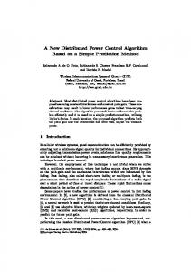
Fig. 2: New CANbus based architecture of fuel management systems. 3.3 Implementation Concepts The Project considers in particular the fuel management of a helicopter with four tanks, and an aircraft with seven tanks. Figure 3 shows a top-view schematic of the helicopter fuel system, which consists in two subsystems (each one with two connected tanks), two refuelling valves, two pumps for engine supply, and a mechanism for balancing the two subsystems.
The research work plan starts with requirement definitions, followed by software development, production of the smart components, and validation in an industrial rig. A simulation task is included for development and testing support. Part of the simulation is based on laboratory experimental rigs.
Fig. 5: Top-view schematic of the airplane fuel system.
Fig. 3: Top-view schematic of the helicopter fuel system. Figure 4 shows a more detailed diagram of the tanks, valves (RV, BV), pumps, sensors (FGT) and piping. Concerning the airplane, figure 5 shows a top view of the fuel system. As can be seen, in this case the system has seven tanks, three in each wing and one more located in the tail. This last one is employed to valance the Centre of gravity of the airplane. This implies a more complex functionality for the fuel system than in the helicopter case.
The main idea devised to get a decentralized control is to maintain a state description of the system along time. The state means which valve is open or closed, which pump is running or not, what are the fuel quantities, etc. A procedure of message exchanging between nodes is defined, so all nodes know at every time the system state. Every state change made by a node is notified to the rest of nodes. Each node knows, in function of the present state if it has to do something new. Apart from normal operations of the system, there are other modes defined for abnormal conditions or for maintenance purposes. There are system high-level orders and information exchanges. A complete protocol has been developed to take into account the complete system functionality.
4 The New Distributed Control System
5 How the System Works
The system architecture has three main levels. Figure 6a shows them: The software, hardware and physical rig. Each device has associated one part of the system. However a device has physical layer; component, a hardware layer; node and a software layer; automata.
For the helicopter case, the fuel system has two operation modes which have been researched on software simulation and test rig. They are normal mode and maintenance mode. The first one has three mode states: Pressure Refuelling, Engine Supply and Transfer. The second one is to manual operation on the components. According to tank distribution showed in figure 5 and the nomenclatures of the table 1, we describe the modes:
Components
Sensor or Actuator
Software
CCC SW and HW
Hardware
CAN Bus
(a)
(b)
•
Pressure Refuelling: It consists in supply fuel at high pressure through the inlet of fuel to refill the system. The valves (RV1 and RV2) must be open to allow fuel flow and the fuel will go in directly to system 1 and by gravity from this to system 2. When it starts, both valves (RV1 and RV2) act according to system tank levels and it will finish when the both tank systems reach the desired quantity fuel.
•
Engine Supply: It consists in supply fuel to the engines of the helicopter when it is in operation. When it starts, both pumps (SP1 and SP2) act starting provisioning both helicopter engines and it will finish when it is deactivated from FMC interface.
Fig. 6: Layers of the architecture system (a). Block Diagram of a Smart Component (b). Table 1: Description of the components. Components FMC BV BP SP1 SP2 RV1 RV2 FGT1A FGT1B FGT2A FGT2B FGT3 FGT4 HLS LLS
Description Fuel Management Controller Balance Valve Balance Pump Supply Pump 1 Supply Pump 2 Refuelling Valve 1 Refuelling Valve 2 Fuel Gauge Transmitter 1A Fuel Gauge Transmitter 1B Fuel Gauge Transmitter 2A Fuel Gauge Transmitter 2B Fuel Gauge Transmitter 3 Fuel Gauge Transmitter 4 High Level Sensor Low Level Sensor
4.1 Smart Components The smart components to be implemented in the Project are fuel sensors, valves and pumps. All components will be able to cooperate using the CANbus. Figure 6b shows a block diagram of a generic smart component. Each component is designed to achieve certain functions, as defined by the corresponding automata. In addition to implementing the fundamental component functions, other tasks of the microcontroller which is embedded in the smart component, are to maintain a usage statistics and to conduct Built-In-Test (BIT) activities after power-up, continuously, or being initiated for diagnostic purposes. The smart components include sensors to monitor their condition. For instance, the balance pump includes temperature and current sensors.
Both above operation modes must be activated manually through the FMC interface. •
Transfer: It is an automatic mode which is activated according to the failure control on components. The idea is to balance the fuel distribution on the fuel system. When the system is in Pressure Supply mode, it will be activated automatically by RV failures and FGT failure. In the first case, a RV1 failure will involve a transfer from system 2 to system 1 and a RV2 failure involves a transfer from system 1 to system 2. Thus, the way to fill the tanks is turned aside to avoid the blocked input. For the second case, a FGT 4 failure will involve that the tank 4 level be measured by LLS and HLS. When the system is in Engine Supply mode, it will be activated automatically by SP failures. A SP1 failure will involve a transfer from system 2 to system 1 and A SP2 failure will involve a transfer from system 1 to system 2. Thus, the fuel is supplied to engine by suction; the intention is to get high level of the appropriate tank to produce as much high pressure outward as possible.
The airplane case, presents specific features. First the influence of fuel distribution among the tanks could affect the instability of the aircraft. So, lateral imbalances due to different fuel weight in the wings should be avoided. Moreover, the tank located an the airplane tail, known as
‘trim tank’ is intended to shift backwards the centre of gravity (CoG) of the airplane during the fly. This has some advantages, among others; it allows reducing the fuel consumption. Of course, the CoG tends to change as fuel is feeding the engines. Thus it is necessary to transfer smoothly fuel from the trim tank to the wings tanks to assure a CoG stable position. The research on the airplane case has been mainly focused with the capacity of the fuel system to control the CoG position and the avoiding of lateral imbalances.
reproduce at fast pace the same logics and sequences of events that happen in the real fuel system. The experimental conditions are thus more stringent that the real ones, since events take place more quickly, meaning larger CANbus load. Since the implementation of smart components comes after software development, something has to be done to get in advance a sort of “smart component”, open to internal code changes during experimental testing. Figure 8 shows a block diagram of what has been done: conventional notsmart valves, level sensors and pumps are used.
5.1 Common Core Controller An important objective of the Project, for an easier certification, is to have a common software core for all smart components. A solution has been reached in terms of automata cooperation. Given a system operation, for instance engine supply, each component involved in the operation behaves as a specific automaton. For instance, an engine supply pump obeys basically (this is a simplified example, without malfunctions) to the automaton depicted in Figure 7. The automaton has two states and two transitions: one to run, and the other to stop.
STOP
Pattern matching … 1 ... 0 0 0 0 ... Activate Component (Interface)
Deactivate Component (Interface)
Change StateVector …1 ... 0 1 0 0 ...
Send message to CAN Bus
Sensor or Actuator
Interface
CAN Module
CCC Program m ing
CAN bus
Local automaton: Engine Supply Pump
Pattern matching … 1 ... 0 0 0 0 ...
Fig. 8: Block Diagram of a Laboratory “Smart
Change StateVector …1 ... 0 1 0 0 ...
RUNNING
Send message to CAN Bus
Fig. 7: Engine supply pumps automaton. All automata, corresponding to all possible behaviours of all components, are codified and put into a library. Each smart component has an I.D. For instance the left refuelling valve knows he is the left refuelling valve. Using this I.D., the smart component selects the automata defining his own behaviour in the system. The state description shared by all components includes bits pointing which system operation is in course. With this information, each component selects and run his specific automaton for the operation. In consequence, it can be said that the system behaviour emerges from the cooperation of local automata.
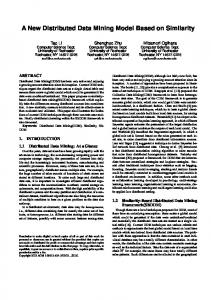
Component” Each conventional component is connected, via simple electronic interface, to a card with the CANenabled microcontroller. The card can be connected to the CANbus. In this way, a laboratory “smart component” is built as a combination of component, interface and card. A side advantage of this structure is that some malfunctions can be easily simulated. Figure 9 shows a photograph of the card with the microcontroller. Fig. 9: Photograph of the Card with the Microcontroller.
6 TEST RIGS One of the Project tasks consists in developing simulation systems to support the research progress. For instance, once the main ideas for decentralized control were elicited, it was very convenient to provide the means to test possible implementations. A direct way for obtaining a test platform is to build a laboratory system with the same structure of tanks, piping, valves, pumps, etc. Sizes and time constants are scaled down, since the focus of the research in this moment is to
A fuel management system has been built using the laboratory smart components. Figure 10 shows a photograph of part of the system with the cards connected via CANbus. The fuel management system is coupled with the physical plant (the tanks and piping), so valves, pumps, and sensors are put in the pertinent places, and connected to the electronic interfaces. Figure 11 shows a block diagram of the laboratory system structure.
7 Conclusions
Fig. 10: Photograph of part of the electronic CANbus system.
Physical Plant (tanks, valves, sensors, etc.)
CAN CAN Module Module
CAN Module
CAN bus
Fig. 11: Block diagram of the laboratory system structure. Figure 12 shows a photograph of the helicopter laboratory system. The development of the common software core has been done with the help of the laboratory systems. The definition of automata has been experimentally checked.
In this paper the present status of a European Research Project on a new CANbus-based avionics system has been described. The research proposed a decentralized control, using smart components. We are working on a new version of the rig model. After our experience on the first model we decide made another one to perform failure and redundancy studies, build the smart components more sophisticated according to extend necessities such as TTCAN implementation, and do demonstration experiments in the industrial rig. The main ideas elicited to obtain a distributed control have been presented. On the basis of these principles, a common software core has been developed, and a distributed fuel management system has been successfully tested in laboratory. The research opens new perspectives for fuel management and other avionics systems. In the future more functionality will be added, increasing the capabilities of the smart components.
Acknowledgments The authors thank to the European Community support, through the Research Project “Smartfuel”. Likewise, the authors thank the collaboration of the research partners
References [1] Avionics Data Buses (www.interfacebus.com). [2] Jian-Guo Zhang, A. Pervez, A. B. Sharma, Avionics data Bus: An Overview, SYSTEMS, IEEE Aerospace and Electronic, February 2003, Vol. 18, Num. 2. [3] J. J. Mayoux, Mzy 19993, STANAG 3910: The data bus of the next generation European fighters, IEEE NAECON’93, Dayton, OH, USA. [4] North Atlantic Treaty Organisation (www.nato.int). [5] Avionics Databus Solutions (www.afdx.com). [6] Jordan, J.R., 1995, Serial Networked Instrumentation, John Wiley & Sons. [7] CAN in Automation (www.can-cia.com) [8] Lawrenz, Wolfhard, 1997, CAN System Engineering, Springer-Verlag.
Fig. 12: Photograph of the helicopter laboratory system. The CANbus has been monitored to determine bus load, to detect any communication problem, and to follow the correct execution of the system operations. The viability of the ideas for decentralized control has been confirmed.
[9] Almeida, L., Pedreiras, P., Fonseca, J.A.G., 2002, The FFT-CAN Protocol: Why and How, IEEE T. Industrial Electronics, vol. 49, num.6, pp. 1189-1201. [10] Hansson, H.A., Nolte, T., Norstrom, C., Punnekkat, S., 2002, Integrating Reliability and Timing Analysis of CAN-Based Systems, IEEE T. Industrial Electronics, vol. 49, num.6, pp. 1240-1250.
Manchester decoding algorithm for Multifunction Vehicle Bus
........................................................
Juime Jiminez, Josi Murtin, Armundo Astarloa, Aitzol Zuloaga Mechanical Product Data Exchange and Integration for PLM .........................................................
.769
.775 Sihem Mostefai, Mohrned Butouche, Abdeluziz Bouras Overview on Dependnhle Embedded Systems in Modem Automotive. . . . . . . . . . . . . . . . . . . . . . . . . . . . . . . . . . . . . . . . . . . . . . . . . . . .781 Fuiza Churfi, Fuycal Scllami Fieldbus Control System Project Support Tool based on Experimental Analysis and Modeling of Communication Bus. . . . . . . . . . . . ,787 Dennis Brnna'uo, Marcio Cunha, Mario Pinotti Jr. Implementation of a Nabdwidth Allocation Scheme in the MS/TP Protocol . . . . . . . . . . . . . . . . . . . . . . . . . . . . . . . . . . . . . . . . . . . . . . .793 Seung Ho Hong, Won-SeokSong, Young-Chun K w n Experimental Controller Tuning and QoS Optimization of a Wireless Transmission Scheme for Real-Time Remote Control Applications. . . . . . . . . . . . . . . . . . . . . . . . . . . . . . . . . . . . . . . . . . . . . . . . . . . . . . . . . . . . . . . . . . . . . . . . . . . . . . . . . . . . . . . . . . .SO1 Athanasiu Punousopoulou, George Nikolukopoulos, Anthony Tzes An MDA Application For a Virtual Reality Environment. ............................................................ .807 Skander Turki, Thierry Sorbno, Adel Sghuier An Event Chain Notification and Management System Using SMS . . . . . . . . . . . . . . . . . . . . . . . . . . . . . . . . . . . . . . . . . . . . . . . . . . . . .813 Adel Ben Mnaouer, Anton Aendmroomer, Lisa Histnanto Application of a Web-based Monitoring and Control system in Plastic Rotational Moulding Machine ......................... . 8 19 Mdrio RodriguezJose' Mendes, Jaime Fonseccr ,824 Industrial applications of wireless networks: A bridge crane distributed control system bascd on Bluetooth ..................... Juan Kcente, Capella Hc.mnandez,Alberto Bonastre Pina, Rafael Ors Curot A new generic architeclure for the implementation of intelligent and distributed control systems based on wireless networks, ....... 830 Juan Vicente Cupella Xcrandez. Alberto Bonustre Pina,Rafael Ors Curot Distributed system for in-line chemical analysis of wastewater based on GPRS mobile communications ....................... .836 Alberto Bonasrrc Pina,Juan Mcenre Ccrpella HernAjer, Rafael Ors Carot, Miguel Peris Tortajado A Web-based interface for the Gryphon robot. . . . . . . . . . . . . . . . . . . . . . . . . . . . . . . . . . . . . . . . . . . . . . . . . . . . . . . . . . . . . . . . . . . . . . .842 Saravancn Mootien, Robert T. F. Ah King, Hurry C. S. Rughooputh Assistance to Maintenance in Industrial Process Using an Augmented Reality System. ..................................... .848 Nadiu Bnati, Noureddine Zerhouni, Kurim Achour Automation o f the Sugar Boiling Process in Batch Vacuum Pans using the ABB-Freelance PLC (AC SOOF) andthe Conductor-NTSCADA .................................................................................. 853 Muheshwurnnth Behury, Robert T. F. Ah King, Hurry C. S.Rughooputh Mobile Tele-Monitoring and Management System for Inter-Cities Public Transportations ................................... .859 K. Darwish. A. R . AI-Ali, M.AL RQUS~ZII Comparison of Different Grid Based Techniques for Real-Time Map Building. ........................................... .863 Ozhun Karaman, H a h n Temeltas . Gigabit Ethernet for Redundant Networked Control Systems. ......................................................... .869 Ramez Daoud, Hany Elsnyed, Hassanein Amer Design Oriented Architecture for Integration Tools - Case Study of Substation Automation Systems .......................... .874 Rogerio Paulo, Adriano Carvalho .SS0 Network Traffic Prediciion and Fault Detection Based On Adaptive Linear Model. ........................................ Jun Lv, Xing Li, Too He A Framework for Dependability Evaluation of Profibus-DP Networks .................................................. .886 Paulo Portugal, Adriano Carvalho A New Distributed Avionics System Based On The Canbus And Homogeneous Nodes ..................................... .892 Jose M Giron-Sierra, Carlos Insaurrulde, Miguel Seminario, Juan F Jimenez Formal Evaluation and Comparison of Real Time Embedded Automotive Networks ....................................... .898 T.Razafindrulambo, Isabelle Augi-Blum Design of a Robust and Adaptive Neural Network for Flexible AC Transmission Systems .................................. .904 Furzun Rashidi, Mehran Rushidi A Tuning Transformer for the Automatic Adjustment of Resonant Loop Antennas in RFID Systems . . . . . . . . . . . . . . . . . . . . . . . . . . . 9 12 Gerald Steiner, Hubert 2 n g l Optimal Self-Adjusting Proportional-Integral-Derivative Regulator. . . . . . . . . . . . . . . . . . . . . . . . . . . . . . . . . . . . . . . . . . . . . . . . . . . . . .917 A1e.randc.r Shubludze, Sergey Ryvkin, Sergey Gulyaev, Alexander Shubludze j r .922 Proposal model for automated stamping process using cylindrical parts . . . . . . . . . . . . . . . . . . . . . . . . . . . . . . . . . . . . . . . . . . . . . . . . . Fethi Abbassi, Noureddine Ben yuhiu, Ali Zghal A Max Plus Algebra Approach For Modeling And Control Of Lots Delivery: Application To A Supply Chain Case Study . . . . . . . . . .926 1. Elmahi. 0.Crunder, .4. Elmoudni
viii
2004 IEEE International Conference on Industrial Technology (ICIT)
A NEW DISTRIBUTED AVIONICS SYSTEM BASED ON THE CANBUS AND HOMOGENEOUS NODES Peter Klose
Jos6 M. Giron-Sierra, Miguel A. Seminario, Carlos C.Insaurralde, Juan F. Jimenez
Autoflug GmbH, Hamburg, Germany.
Universidad Complutense de Madrid, Dep. ACYA AV.Complutense S / N , 28040 Madrid, Spain ~ o n
[email protected] i
Jose A, Frutos, Ignacio Perez, Esther Buesa, Universidad de Alcala, Dep. Informatica y Automatica, Spain
Abstract- In this paper a new avionic system based on the CANbus is introduced. Fieldbuses offer less weight, standardised technology and simpler system architecture. This appears in contrast with conventional avionic systems. The paper describes main approaches and results of a European Research Project. The research proposes a completely distributed contro1, using smart components connected with a CANbus. The research focuses on the fuel management system of helicopters and aeroplanes. The paper describes the monitoring and control problem to be solved, the distributed control architecture and software, the smart components, and development steps till verification on experimental rigs.
this state that is pertinent for its decisions. Then a kind of holonic concept is present. The development of this idea required the design and implementation of experimental testing rigs, with scaled down replicas of the fuel systems. An initial version of the common code has been developed, and if was tested successfully. The paper starts with an overview of avionic systems. Then it presents the main purposes and means of the Research Project, with a discussion of fieldbuses. Then it focuses on the architecture and functionality of the new distributed control system. A description of the way we devised for the information sharing between nodes, and the common code, is given. Then the paper describes the test rigs, showing some experimental results. And finally the paper presents the conclusions and future.
Key Words: CAN Bus, Avionics, Fieldbuses, Smart Device, Fuel Management System.
2 Avionics Systems and Fieldbuses 1 Introduction
2.1. Avionics Systems
Classical avionic systems usually consist in a central computer with poinl-to-point connections to sensors and actuators. This involves the use of massive wiring and dense connectors. The possibility of replace those by a simple fieldbus should have many positive consequences: less weight and less system connection complexity. Less weight, simple maintenance and more reliability are very important features in the aerospace context. Redundancy can be easily applied, and reliability can increase. A main difficulty to promote new advances in the aerospace industry is that they must be certified. Smart components are an important industrial trend. A way to create a distributed control system is to use as nodes smart components. The distribution is implemented by Fieldbuses. The paper presents the main ideas of a European Research Project which focuses on the fuel management for helicopters and airplanes. The central computer for the fuel management disappears, and is substituted by a network node with human interface capabilities. The implementation of the project requires describing precisely the actions of the components during refuelling and normal flight. It was decided that a description of the state of the system is maintained by the management system at all times, and that each node knows the part of
Avionic manufacturers are taking advantage of the advances in computing technology to reduce the airborne weight and the time for designing, assembly, and integration but increasing system performance at the same time. It motivates to cohsider replacing point-to-point wiring and unidirectional data buses with faster and lighter bi-directional data buses. The most important factors of avionics buses include; deterministic behaviour, fault toIerance, and redundancy.
0-7803-8662-0/04/$20.00 Q2004 IEEE
2.2.1 Certificated Data Buses Our intention is to present briefly, the most commonly proposed data buses to place the researching environment of the project. According to standardization norms, we cite the next avionics data buses:
ARINC 659: Backplane Dala Bus for Integrated Modular Avionics operates at 6OMbps as a commercial aviation bus. The SAFEbus architecture, developed by Honeywell is based on ARINC 659 111. ARTNC 629: MuLti-Transmitter Data Bus is a serial data bus which operates over cable at 2 Mbps and it was developed by Boeing [I].
892
implementations, the research phase is the first step to get real application. Our proposal is an attractive idea to use fieldbuses like another alternative of avionics data bus. At this point, it is interesting to notice that exist many tools and support to work with CANbus.
ARINC-429: Digital Information Transfer System. It is a point-to-point, 2-wire Bi-Polar Return-to-Zero signal bus of 32 bit data at lO0K or 1 2 . X bit rate. It is similar to ARINC 575, but being replaced by 629 [ 11. IEEE-std-1393: Spaceborne Fiber Optic Data Bus operates at 1 Gb/s 111.
2.2.1 CANbus There are few incipient applications of the CANbus in avionics and aerospace, as reported in the web page of CAN In Automation organization [71. The book [XI is a recent compendium of theory and applications of the CANbus. There are active research lines about the CAN protocol, being published in TEEE proceedings on factory automation, and conferences of the CAN in Automation organization. A recent volume of IEEE Transactions on Industrial Electronics (December 2002) presented some articles on the topics [9, IO].
IEEE-Std-1349.5 1995: IEEE Standard for Module Test and Maintenance Bus Protocol. It specifies a serial, backplane, test and maintenance bus between a Test Control Master and up to 250 Slave modules [l].
E E E 1355.2: SpaceWire, based on the HIC (IEEE-1355) bus, and Low Voltage Differential Signaling (EM-644).It is controlled by the European Space Agency, for the ECSS (European Cooperation for Space standardization) 11I.
SAE ASOX.1 Linear Token Passing Mulhplex Data Bus is a High Speed Data Bus (HSDB). A fiber optic bus
3 Description of the Research Project
operating at 80 Mbps [I].
3.1 The Project Consortium
SAE AS4075 is a High-speed Ring Bus (HSRB). It is a serial bus [l].
It is a research and technological development Project within the fifth framework programme of the European Commission for three years which participates five Companies and three Universities. Four of the industrial partners participating in the Project are producers of valves, pumps and sensors. Universities provide scientific support, and contribute also with protocol and automata definitions, One of the partners produces the digital electronics to be embedded into the components (each component producer puts this into his component). The other two industrial partners are users of the final product.
ASCB: Avionics Standard Communicafions Bus. A highspeed, bi-directional digital data bus [l].
MIL-STD-1553: It is the military standard for an aircraft internal time-division command/response multiplex data bus. It is a serial bus at 1 Mbitls [2]. MIL-STD-1773: It is the Fiber optic version of MIL-STD1553B data bus which was developed to flight critical conditions. It was implemented by NASA and the Navy in the early 1990s [2j.
3.2 Design Concepts
STANAG 3910: It is a dual-rate data bus hased on the commandhesponse protocol [3] was developed by NATO [4] in the early 1990s. AFDX: Avionics Full Duplex Switched Ethernet. ARINC-664 Standard adopts the key elements from AFD standardize a deterministic Network for aircraft and it is used on the Airbus A380 as main avionics data bus & on the A400M [5]. 2.2 Fieldbuses Nowadays, fieldbuses are an important alternative for the architecture of systems with sensors and actuators. The book 163 describes twelve different serial networking standards, and descrihes their application to factory automation, laboratory and medical automation, intelligent buildings, and transport. The use of the fielbuses (CAN, TTCAN, etc) is growing up in many applications. No many projects are being developed on airbome system. Like another technology
Figure 1 shows the conventional centralized system architecture for the fuel management system. The architecture implies a lot of wiring and a large connector (possibly with many pins) in the central computer. Figure 2 shows the system architecture proposed in this research. It is based on a fieldbus. Wiring is simplified, with less weight. Information obtained by sensors, and orders given to actuators, are transmitted in digital format. Sensors and actuators are nodes of the system, exchanging messages through the bus. An important objective of the Project is to obtain a completely decentralized functionality. In consequence the central computer is suppressed: there will be just another node for human interface and system coordination role. Smart components are valves, pumps, and sensors, with augmented functionality. The most important part of their capabilities is related to make possible the distributed control of system operations. In addition, they will have self-testing capabilities, and keep individual records €or maintenance purposes.
893
Fig. 1: Conventional architecture of fuel management systems.
4
f?
-[=cLNxsI
I
I
I
b
B
Fig. 2: New CNVbus based architecture of fuel management systems.
3.3 Implementation Concepts The Project considers in particular the fuel management of a heIicopter with four tanks, and an aircraft with seven tanks. Figure 3 shows a top-view schematic of the helicopter fuel system, which consists in two subsystems (each one with two connected tanks), two refuelling valves, two pumps for engine supply, and a mechanism for balancing the two subsystems.
Fig. 4: Details of the helicopter fuel system.
3.4 Development and Research The research work plan starts with requirement definitions, followed by software development, production of the smart components, and validation in an industrial rig. A simulation task is included for development and testing support. Part of the simulation is based on laboratory experimental rigs.
Fig. 5: Top-view schematic of the airplane fuel system. The main idea devised to get a decentralized control is to maintain a state description of the system along time. The
Fig. 3: Top-view schematic of the helicopter fuel system. Figure 4 shows a more detailed diagram of the tanks, valves (RV, BV), pumps, sensors (FGT) and piping. Concerning the airplane, figure 5 shows a top view of the fuel system. As can be seen, in this case the system has seven tanks, three in each wing and one more located in the tail. This last one is employed to valance the Centre of gravity of the airplane. This implies a more complex functionality for the fuel system than in the helicopter case.
state means which valve is open or closed, which pump is running or not, what are the fuel quantities, etc. A procedure of message exchanging between nodes is defined, so all nodes know, at every time the system state. Every state change made by a node is notified to the rest of nodes. Each node knows, in function of the present state if il has to do something new, Apart from normal operations of the system, there are other modes defined for abnormal conditions or for maintenance purposes. There are syslem high-level orders and information exchanges. A complete protocol has been developed to take into account the complete system I functionality. 894
4 The New Distributed Control System
5 How the System Works
The system architecture has three main levels. Figure 6a shows them: The software, hardware and physical rig. Each device has associated one part of the system. However a device has physical layer; component, a hardware layer; node and a software layer; automata.
For the helicopter case, the fuel system has two operation modes which have been researched on software simulation and test rig. They are normal mode and maintenance mode. The first one has three mode states: Pressure Refuelling, Engine Supply and Transfer. The second one is to manual operation on the components. According to tank distribution showed in figure 5 and the nomenclatures of the table 1, we describe the modes:
Pressure Refuelling: It consists in supply fuel at high pressure through the inlet of he! to refill the system. The valves (RV? and RV2) must be open to allow fuel flow and the fuel will go in directly to system 1 and by gravity from this to system 2. When it starts, both valves (RVl and RV2) act according to system tank levels and it will finish when the both tank systems reach the desired quantity fuel. Engine Supply: It consists in supply fuel to the engines of the helicopter when it is in operation. When it starts, both pumps (SP1 and SP2) act starting provisioning both helicopter engines and it will finish when it is deactivated from FMC interface.
Fig. 6: Layers of the architecture system (a). Block Diagram of a Smart Component (b). Table 1: Description of the components.
SP2 RV I RV2
FGTlA FGTlB FGT2A FGT2B FGT3 FGTQ
H LS LLS
1
I
Fuel Mana ement Controller Balance Valve Balance Pum Su I Pum 1 Su 1 Pum 2 Refuelling Valve 1 Refueliing Valve 2 Fuel Gauge Transmitter 1A Fuel Gauge Transmitter I B Fuel Gauge Transmitter 2A Fuel Gauge Transmitter 2B Fuel Gauge Transmitter 3 Fuel Gauge Transmitter 4 High Level Sensor Low Level Sensor
Both above operation modes must be activated manually through the FMC interface.
Transfer: It is an automatic mode which is activated according to the failure control on components. The idea is to balance the fuel distribution on the fuel system.
~
When the system is in Pressure Supply mode, it will be activated automatically by RV failures and FGT failure. In the first case, a RV1 failure will involve a transfer from system 2 to system 1 and a RV2 failure involves a transfer from system 1 to system 2. Thus, the way to till the tanks is turned aside to avoid the blocked input. For the second case, a FGT 4 failure will involve that the rank 4 level be measured by LLS and IUS.
4.1Smart Components
The smart components to be implemented in the Project are fuel sensors, valves and pumps. All components will be able to cooperate using the CANbus. Figure 6b shows a block diagram of a generic smart component. Each component is designed to achieve certain functions, as defined by the corresponding automata. In addition to implementing the fundamental component functions, other tasks of the microcontroller which is embedded in the smart component, are to maintain a usage statistics and to conduct Built-In-Test (BIT) activities after power-up, continuously, or being initiated for diagnostic purposes. The smart components include sensors to monitor their condition. For instance, the balance pump includes temperature and current sensors.
When the system is in Engine Supply mode, it will be activated automatically by SP failures. A SP1 failure will involve a transfer from system 2 to system 1 and A SP2 failure will involve a transfer from system 1 to system 2. Thus, the fuel is supplied to engine by suction; the intention is to get high level of the appropriate tank to produce as much high pressure outward as possible. The airplane case, presents specific features. First the influence of fuel distribution among the tanks could affect the instability of the aircraft. So, lateral imbalances due to different fuel weight in the wings should be avoided. Moreover, the tank located an the aimlane tail. known as
8 95
‘trim tank’ is intended to shift backwards the centre of gravity (COG)of the airplane during the fly. This has some advantages, among others; it allows reducing the fuel consumption. Of course, the COGtends to change as fuel is feeding the engines. Thus i t is necessary to transfer smoothly fuel from the trim tank to the wings tanks to assure a COG stable position. The research on the airplane C ~ S Ehas been mainly focused with the capacity of the fuel system to control the COG position and the avoiding of lateral imbalances.
reproduce at fast pace the same logics and sequences of events that happen in the real fuel system. The experimental conditions are thus mare stringent that the real ones, since events take place more quickly, meaning larger CANbus load. Since the implementation of smart components comes after software development, something has to be done to get in advance a sort of “smart component”, open to internal code changes during experimental testing. Figure 8 shows a block diagram of what has been done: conventional notsmart valves, level sensors and pumps are used.
5.1 Common Core Controller An important objective of the Project, for an easier certification, is to have a common software core for all smart components. A solution has been reached in terms of automata cooperation. Given a system operation, for instance engine supply, each component involved in the operation behaves as a specific automaton. For instance, an engine supply pump obeys hasically (this is a simplified example, without malfunctions) to the automaton depicted in Figure 7. The automaton has two states and two transitions: one to run, and the other to stop.
Fig. 8: Block Diagram of a Laboratory “Smart
n
ccc
I
; Programming
Component” Each conventional component is connected, via simple electronic interface, to a card with the CANenabled microcontroller. The card can be connected to the CANbus. In this way, a laboratory “smart component” is built as a combination of component, interface and card. A side advantage of this stkcture is that some malfunctions can be easily simulated. Figure 9 shows a photograph of the card with the microcontroller. All automata, corresponding to all possible behaviours of all components, are codified and put into a library. Each smart component has an I.D.For instance the left refuelling valve knows he is the left refuelling valve. Using this I.D., the smart component selects the automata defining his own hehaviour in the system. The state description shared by all components includes bits pointing which system operation is in course. With this information, each component selects and run his specific automaton for the operation. In consequence, it can be said that the system behaviour emerges from the cooperation of local automata.
Fig. 9: Photograph of the Card with the Microcontroller.
1
6 TEST RIGS One O f the Project t2tSkS COnSiStS in developing Simulation systems to support the research progress. For instance, once the main ideas for decentralized control were elicited, it was very convenient to provide the means to test possible implementations. A direct way for obtaining a test platform is to a laboratory system with the same structure of tanks, Piping,
valves, pumps, etc. Sizes and time constants are scaled dawn, since the focus of the research in this moment is tog96
A fuel management system has been built using the laboratory smart Components. Figure 10 shows a photosaph of of the system with he cards via C m h u s . me fuel management system is coupled with the physical plant (the tanks and piping), SO valves, pumps, and sensors are put in the pertinent places, and connected to the electronic interfaces. Figure 1 1 shows a block diagram ofthe laboratory system stmcture.
7 Conclusions
Fig. 10: Photograph of part of the electronic CANbus system.
I I I
1 1 I
I I
1 I
I
I
1
Fig. 1 1: Block diagram of the laboratory system structure. Figure I2 shows a photograph of the helicopter laboratory system. The development of the common software core has been done with the help of the laboratory systems. The definition of automata has been experimentally checked.
In this paper the present status of a European Research Project on a new CANbus-based avionics system has been described. The research proposed a decentralized control, using smart components. We are working on a new version of the rig model. After our experience on the first model we decide made another one to perform failure and redundancy studies, build the smart Components more sophisticated according to extend necessities such as TTCAN implementation, and do demonstration experiments in the industrial rig. The main ideas elicited to obtain a distributed control have’been presented. On the basis of these principles, a common software core has been developed, and a distributed fuel management system has been successfully tested in laboratory. The research opens new perspectives for fuel management and other avionics systems. In the future more functionality will be added, increasing the capabilities of the smart components.
Acknowledgments The authors thank to the European Community support, through the Research Project “Smartfuel”. Likewi se, the authors thank the collaboration of the research partners
References [ l ] Avionics Data Buses (www.intcrfacchus.com). [Z] Jian-Guo Zhang, A. Pervez, A. B. Sharma, Avionics data Bus: An Overview, SYSTEMS, IEEE Aerospace and Electronic, February 2003, Vol. 18, Num. 2.
[3] J. J. Mayoux, Mzy 19993, STANAG 3910: The data bus of the next generation European fighters, IEEE
NAECON’93, Dayton, OH, USA. [4] Nonh Atlantic Treaty Organisation (www.nnto.int). [5] Avionics Databus Solutions {www.afdx.com).
[6] Jordan, J.R., 1995, Serial Networked Instrumentation, John Wiley & Sons. [7] CAN in Automation (www.can-ciamm)
[SI Lawrenz, Wolfhard, 1997, CAN System Engineering, Springer-Verlag.
Fig. 12: Photograph of the helicopter laboratory system. The CANbus has been monitored to determine bus load, to detect any communication problem, and to follow the correct execution of the system operations. The viability of the ideas for decentralized control has been confirmed.
[9] Almeida, L., Pedreiras, P., Fonseca, J.A.G., 2002, The FFT-CAN Protocol: Why and How, IEEE T. Industrial Electronics, vol. 49, num.6, pp. 1 189-1201. [lo] Hansson, H.A., Nolle, T., Norstrom, C., Punnekkat, S., 2002, Integrating Reliability and Timing Analysis of CAN-Based Systems, IEEE T. Industrial Electronics, vol. 49, num.6, pp- 1240-1250.
897