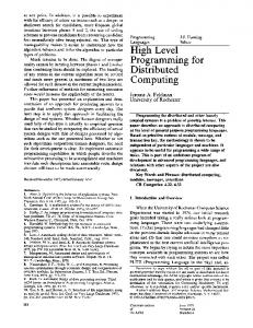
A new approach for distributed computing in avionics systems Miguel A. Sánchez-Puebla EADS Spain Avda John Lennon s/n Getafe, 28906, Madrid, Spain Email:
[email protected]
Jesús Carretero Computer Science Department Universidad Carlos III de Madrid, Avda. Universidad 30 Leganés, 28911, Madrid, Spain
Abstract
Historically, a typical avionics system architecture has been designed as a federated architecture of black-boxes with well-defined functions and implemented on fully dedicated computers. The new Integrated Modular Avionics (IMA) architecture relies on an architecture more similar to conventional computers, where several general-purpose processors are connected through a bus and all the Inputs/Outputs (I/O) come from the I/O units (like Remote Interface Units, RIUs) through the bus to the processors. This architecture imposes a heavy traffic on data networks, which cannot be satisfied by traditional buses such as the MIL-STD-1553, but still requires determinism, which cannot be provided by general-purpose networks. In this paper, we describe the basics of IMA and the communication network designed for the new Airbus 380. The preliminary evaluation results show the feasibility of the IMA approach.
1 Introduction Historically, aviation-based computing systems have used a federated design approach, where functions (and their associated criticality) are isolated from others by confining them into dedicated boxes. However, the trend of manufacturers in recent years has been to integrate numerous functions into single computing systems with different levels of criticality [1]. A typical avionics system architecture is designed as a federated architecture of black-boxes. Each box can be a hardware/software (Hw/Sw) configuration totally different to the others (i.e. Central Processing Unit, language, Operating System). This architecture is inherently robust and fault-tolerant. The applications are physically protected from one another so that failures of one or more applications do not affect others. For example, in Figure 1, a Line Replaceable Unit (LRU) fails without affecting the remainder systems. However, this architecture is very expensive to build in terms of cost, power consumption, cooling, and weight. Moreover, adding new functions means adding new boxes. Thus, modifications, upgrades and improvements usually convey serious drawbacks in terms of complexity, costs, time, etc.
Figure 1 Federated architecture for avionics systems
To overcome those disadvantages, a new avionics architecture model, known as IMA (Integrated Modular Avionics), has been developed. In this paper, we introduce the IMA model and a new
Copyright held by the author
579
network switch devised for this type of architecture. Section 2 describes the IMA. Section 3 presents the features of the network interconnection devices. Initial evaluation results are shown in Section 4. Finally, some conclusions and future work are shown in Section 5. 2 IMA architecture principles description Considering that all the computers have the same functionalities (input acquisitions, avionics processing, algorithm computation, output generation...), it is tempting to specialize resources by functionalities, achieving this by ensuring suitable segregation between user systems. That is the Integrated Modular Avionics (IMA) concept, where “integrated” must be understood as sharing the resources by several systems [8]. IMA means using an architecture more similar to conventional computers, where several general-purpose processors are connected through a bus, and all the Inputs/Outputs (I/O) come from the I/O units (like Remote Interface Units, RIUs) through the bus to the processors (see Figure 2). This new avionics architecture approach is based on the following general principles: - Support services for operational functions. - Sharing of common resources (power supply, CPU, memory, I/O, Communications buses…) among several functions, with adequate segregations (e.g. robust partitioning). - Use of generic modular resources (standardization of modules, I/O types…). - Allocation of resources defined by static configuration. - Separation of shared I/O acquisition and generation data from processing. - Uploadable and downloadable modules. - Use of a standardized interface (API) between applications and executive, which is based on ARINC 653 (APEX), to ensure applications portability and hardware/software independence. - Customization and evolution capabilities. The APEX interface satisfies the common real-time requirements: specific timing constraints and concurrency between the processes being part of a partition and a scheduling model that allow concurrency between partitions [11].
Figure 2 IMA architecture for avionics systems
Two classes of major modules have been defined for the IMA architecture: - IOM (Inputs/Outputs Module): to manage the transfer of different types of dedicated Input/Output (ARINC 429, discrete wires, CAN bus…) to/from a bus, generally shared among several systems (e.g. AFDX Ethernet, Fibre Channel…) - CPIOM (Core Processing Inputs/Outputs Module): to execute specific avionics functions (applications software), and the input/output associated to those systems. The CPIOMs replace the traditional black-box concept. They provide computing capabilities to various applications via a standardized interface.
580
This means that part of system Inputs/Outputs will be deported to one or more IOMs and will have to be transmitted among the CPIOM and the IOM(s). Such inter-module exchanges are made via the shared aircraft network (AFDX or Fibre Channel), and only the services included in the Avionics Application Software Standard Interface (ARINC 653) can be used [3]. The basic principle of IMA is "sharing". This is accomplished by: - Sharing of processing resources through a robust partitioning mechanism that enables the various applications to be executed by the same computational resource providing protection through space and time segregation. - Sharing of communication network, because a unique communication media is used among the various modules, but also between these modules and the remaining boxes. - Input sharing, because input data is acquired only once (with the exception of redundancies required to meet safety and schedulability constraints) and redistributed to user systems via the communication network. Specific partitions within an IMA system are scheduled on a fixed, cyclic basis (a major time frame of fixed duration). The order of partition activation is static and fully defined at configuration time using configuration tables [9]. According to [9] a uniprocessor system consisting of a fixed set of applications partitions executing atomic instructions and InterPartition Communication (IPC) services is equivalent to a federated architecture. It must be verified that each atomic instruction has read only access to its inputs and write access to its outputs parameters. For IPC the condition to be guaranteed is that the IPC service has access to both the communication resources and the application resources of the requestor. Time is unique and independent of partition execution within an IMA module. There are not time capabilities relative to a specific partition execution. The O/S is responsible for providing time slicing, deadline, periodicity, delays and time-outs, and these mechanisms are only accessed through attributes or services provided by the ARINC 653 APEX. 3 Network interconnection devices IMA architecture imposes very strong requirements on the communication network, requirements that cannot be satisfied by traditional avionics buses, such as MIL-STD-1553 or ARINC 429. Thus, a lot of research groups devoted their efforts to look for faster and open system avionics networks to replace the old ones [16]. One of them is the ADN (Aircraft Data Network) Working Group, whose objective is to develop standards for the Ethernet-based data networks for new airplane designs. The ADN Working Group presented the Project Paper 664, Aircraft Data Networks with the complete specification of a new communication network using Ethernet Physical and Data Link Layer specification, IPv6, Internet-based protocols and services, Internet-based address structure, prioritised services through network, re-structured network management to serve both avionics and passenger-information requirements, deterministic network services to adapt nondeterministic Ethernet messaging to the flight-critical requirement for speed and reliability. They proposed and implementation example, called Aircraft Full Duplex Network (AFDX), whose main goal is to support the IMA concept of partitioning by providing secure and reliable communications for the exchange of both critical and non-critical data between avionics applications. AFDX is based on ARINC 664 data networking standards [2]. AFDX employs communications techniques derived from the commercial Ethernet standard, IEEE 802.3, along with aviationspecific requirements, such as "virtual links", "traffic shaping" between end systems, and interfaces between line replaceable units (LRUs) and the network. These refinements guarantee that critical information is delivered on time and that sufficient bandwidth is allocated to necessary data flows. Timing verification is important in avionics functions, where data has to reach its destination within strictly defined limits, thus AFDX boards have time code processors
581
that generate time stamps and allow to measure how long it takes a packet of information to go from an end-system, through a switch and to another end system. The standard Ethernet switch has been also modified due to IMA requirements in terms of safety, segregation and partitioning. Redundant networks are also used to satisfy network reliability and safety criteria. Figure 3 shows the AFDX network architecture.
Figure 3 AFDX network architecture
AFDX Ethernet driver and hardware provide a packet-switching network [5], specifically FullDuplex Switched Ethernet (FDSE), that entirely removes and avoids collisions by satisfying two operational constraints [4]: adding a switch to filter Ethernet frames or forward them to the right output ports, and connecting only one station to a switch port using a link capable of supporting simultaneous transmission and reception. When a switch receives a frame, depending on the destination Media Access Control (MAC) address, it looks on a table for a list of output ports to send the frame to. It will then forward the frame to these ports and only to these ports. The switches ensure the relay of Ethernet frames from one transmitting station to one or more receiving stations. However, using standard full-duplex switched Ethernet rises some limitations and, therefore, some features must be added [6]: - Broadcast protection, - Multicast support, - Performance guarantee through delay bounds for data exchanges, - High transmission reliability, which means that data packet loss, must be minimized, - Performance guarantee must be provided to each transmission whatever the state of the network: in other terms, faced to misbehaving transmissions, the network shall maintain performance guarantees for healthy transmissions. 4 AFDX network evaluations We have evaluated AFDX on two VME64 PPC 750 CPU boards [12] running VxWorks AE: 1.0 (beta version) by Wind River [14] connected through two AFDX End-System (E/S) in a pointto-point scheme (see Figure 4). The final evaluation goal was, not only how fast the architecture is, but how easy is to get working an application using the APEX services, and how predictable the software would be. The high-level testing application was written in Ada95 [13] using the tasking model with priorities and the drivers for the I/O board in ANSI C language. ARINC 653 does not recommend the use of the Ada tasking because of the absence of determinism. Instead, a Ravenscar Profile has been used [7].
582
Figure 4 AFDX evaluation testbench
Our main tests run a Hard Real-Time application sharing I/O resources and exchanging data by Ethernet in an ARINC 664 way. The hard real-time constraint has a minor frame of 80 ms. The main part of the software is an aperiodic tasking scheduler based on Rate Monotonic Analysis (RMA) [10]. This scheduler scheme has been issued based on the ARINC 653 APEX by using a single process per partition (additional process with a high priority have been issued to handle with the devices drivers) and one partition per CPU board. Each process requests a “PERIODIC_WAIT” service to get the equivalence with “delay_until” . The inter-partition communication has been issued in sampling mode, and each I/O device is handled by one independent process. Blackboard services have been used to read/write onto these devices. Opposite to initial predictions, the main concerns to fit the hard real-time requirements have not been related to neither Ada tasking, nor resources sharing, nor data exchanging. All these have introduced a natural consumption of time, but always (See Table 1) inside time limits and according to their access time, accommodated to fit the 80 ms scheduler. All tasks are schedulable at theirs partitions according to [15] Intra-partitions (µsg) Inter-partitions (µsg) Write Read Write Read Single Access (4 Bytes) 1 3 46 65 Block Transfer (64 Bytes) 46 51 46 52 Multiplexed Block Transfer (64 Bytes) 46 49 47 52 Block Transfer (8192 Bytes) 542 355 310 395 Multiplexed Block Transfer (8192 Bytes) 221 190 195 283 Table 1. AFDX (inter) and backplane (intra) transmission delays
Despite these facts, we observed that an overrun deadline occurred periodically. We traced this characteristic to the fact that the timer provided by the compiler/APEX/CPU board is 16.66 ms and the system timer provided by the compiler/OS/CPU board is based, of course, on that timer. Therefore the 1st delay of 80 ms is converted to 5 system ticks, i.e., 5*16.66 = 83.33 ms of effective delay. Then the 2nd delay is 80-3.33 = 76.66 ms, again converted in 5 system ticks (i.e. 83.33ms). Then the 3rd delay is 73.33 ms, again 5 system ticks. Then the 4th delay is 70 ms, and again 5 system ticks. Finally, the 5th delay is 66.66 ms and now this time is converted to 4 system ticks (i.e. 4*16.66=66.66ms). Thus, the sequence is 83.33ms, 83.33ms, 83.33 ms, 83.33 ms, and 66.66 ms (overrun) and so on (see Figure 5). 5 ticks = msg
83.35 ticks = msg
80 mseg
83.35 ticks = msg
80 mseg
83.35 ticks = msg
80 mseg
4 ticks= 66.6 ms ⇒ over-run
83.3
80 mseg
80 mseg
Figure 5 Periodic overrun example
583
The same scheduler scheme has been issued avoiding the APEX services, but using an “delay_until” sentence. Therefore the “delay_until” is used to obtain the next self -compensating period. In this case the compiler/OS/ CPU board time is again based on the OS/CPU board timer and then the results have been the expected. 5 Conclusions The use of an APEX standard will allow more complex system to work in less time and with less effort. But the upper layers are (always) based on the lower layers. Our experience shows that using an APEX standard eases the start up of an application in comparison with previous standards. The evaluation also shows that besides, the ability of an APEX stantard to guarantee a constant-time context (independent of the number of the tasks) of 80 ms, for instance, is worthless if the compiler/OS/CPU board can not guarantee a trusty timer. At least three timers models should be provided by the compiler/OS/CPU board: Chime model with large period, very low overhead, for applications not needing true real time (i.e. Calendar.Clock); Alarm model with time events implemented by an event queue and just one wide range timer to interrupt the next expired event, and chime + alarm model if the CPU board does not include an alarm timer wide enough. In this case two medium range timer shall be needed. If these models are not available, the best solution is to implement a ‘tick’ by using a semGive/semTake strategy that can be adapted quite easily to each context/board. A major attraction of AFDX is its ability to free avionics data transfer in integrated avionics systems from the logistical limitations of a backplane bus. Configuration tables allow to define partitions and to distribute computing modules through several computers tightly integrated by AFDX. This increases flexibility in placing computing resources and reduces the system updates complexity. However, configuration tables activities should be improved by using a graphical application in order “to visualise” what is in each parti tion and warning the system integrator that the resources are not properly balanced among partitions. Currently is rather hard to configure an IMA system. AFDX has demonstrated to be deterministic, reliable (is a dual network), and fast enough to satisfy transmission requirements. However, in order to validate the model, further research has to be carried out in the heavily loaded environment of an airplane. This requires an IMA simulator for a complete airplane, with intense signal traffic across the network. 6
References
[1] [2] [3] [4] [5] [6] [7] [8] [9]
RTCA/DO-178B Software Considerations in Airborne Systems and equipment Certification ARINC Specification 664. Aircraft Data Network. ARINC Specification 653. Avionics Application Software Standard Interface. 1995 IEEE Std 802.3, 2000 Edition: Full-duplex Operations IEEE Std 802.1d: Media Access Control Bridge IEEE Std 802.1q: Virtual Bridged Local Area Network B. Dobbing, “Building Partitioned Architectures based on Ravenscar Profile”. SIGAda November 2000 G. Romanski, “High Integrity Softw are for High Integrity Systems”, SIGAda 2000. B.L. Di Vito, “A formal Model of Partitioning for Integrated Modular Avionics”, NASA/CR -1998-208703, August 1998 [10] K. Tindell, “Deadline Monotonic Analysis,” Embedded Systems Programming, June 2000 http://www.embedded.com/2000/0006/0006feat1.htm. [11] Aerospace Recommended Practice 4754 Certification Considerations for Highly Integrated or Complex Aircraft Systems, 1996. [12] Radstone PPC 4B Manual Rev A No. PPC4B-0HH 2.001 [13] WindRiver, “GNU Toolkit User’s Guide”, WindRiver 2.002 [14] WindRiver, “VxWorks Programmer’s Guide”, WindRiver 2.002 [15] L. Kim, “Software architecture supporting integrated real -time systems”, Younis, 2.001 [16] Murdock JK, Koenig JR. Open systems avionics network to replace MIL-STD-1553. In Proceedings of the AIAA/IEEE 19th Digital Avionics Systems Conference, Philadelphia, PA, 2000.
584