1
A NEW DISTRIBUTED SOFTWARE ARCHITECTURE WITHIN THE PYRO ENVIRONMENT FOR A QUADRUPED ROBOT GIUSEPPINA GINI Dipartimento di Elettronica e Informazione, Politecnico di Milano, piazza Da Vinci 32, 20133 Milano, Italy
[email protected]
PAOLO BELLUCO Dipartimento di Meccanica, Politecnico di Milano, Via G. La Masa 1, 20156 Milano, Italy
[email protected]
THOMAS FERRARI Dipartimento di Elettronica e Informazione, Politecnico di Milano, piazza Da Vinci 32, 20133 Milano, Italy
[email protected] The robot platforms are usually composed with a bunch of different elements coming from different technologies, therefore merging and handling information, from sensors to actuators, is a complex problem. Our aim is obtain a controller of a legged robot walking on unstructured environments and to develop robust algorithms to coordinate the movement according to a variety of requirements. We built a small 4-legged autonomous robot, named Warugadar, endowed with monocular camera, piezoelectric contact sensors and ZigBee transceivers, thought to be modular and scalable. In fact it is possible to change hardware components without deeply modifying its software architecture. Each component of the robot (data acquisition board for sensors, camera, motor board) is stand-alone and shares information and receives commands from a brain unit on a remote computer powered by Pyro (Python Robotics). Pyro is an open-source robotics toolkit written in Python for exploring topics in AI and Robotics, which introduces generic robot abstractions that are uniform across a number of robot platform regardless of their size and morphology. In this way it is possible to control the behaviors of Warugadar.
1. Introduction In the paper we illustrate a quadruped robot developed as a test-bed for a modular software and hardware architecture. In particular we present the firmware, the sensory system, the gaits for this robot, and the autonomous behaviours implemented. The novelty of our design is in the integration of simplified solutions, compatible with a low cost design, but still able to create
2
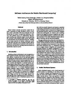
good mobility and autonomy. Quadruped are still a challenge in robotics because controlling them is more difficult than controlling wheeled robots. So far quadrupeds with 8 to 12 degrees of freedom are available, and a few gaits can be achieved on them. As the technology of building them needs to grow and their controller to be easily modified, we targeted our research to the construction of a simple 12 dof robot, equipped with pressure sensors under its legs, built with a modular architecture, able to implement some simple behaviors, as we will show in the following sections. 2. Hardware: mechanical structure, actuators and sensors The mechanics of the robot presents 12 dof in the legs. The main-body of Warugadar (Fig. 1) is made by a Plexiglas sheet. The leg links are built from aluminum. Each leg has three degrees of freedom, and its kinematic structure consists of three rotation joints, R-R-R, where the rotation axis of the first joint, the hip, is perpendicular to the rotation axes of the other two joints, the knee and the ankle, which have parallel rotation axes.
Figure 1. Front view of Warudagar
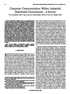
The kinematics has been formulated in the DH notation for each leg, and for the center of mass. Fig. 2 shows the coordinate systems defined on the legs. The dynamic equations (Newton.Euler approach) have been solved to check the correctness of the mechanical structure. We developed a Matlab simulator to study the gaits of the robot. A gait is a sequence of movements by which a legged system moves. The most important aspect of legged locomotion is stability [1, 5, 6]. In the case of static motion, stability is achieved when the projection of the robot's center of mass falls within the supporting polygon. The Stability Margin
3
of a gait is the minor of the minimum distances between the mass center and the perimeter of the supporting polygon, for all the robot configurations. The greater the stability margin is, the more the given gait will be able to maintain stability under dynamic disturbances. In case of marginally static gaits, the projection is on the border of the supporting polygon.
Figure 2. Kinematic model of the leg. Reference systems and DH table.
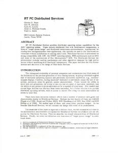
The motion trajectory of the foot, can be divided in two phases. During the stance phase the foot acts as a pivot, supporting the weight of the main body and propelling it towards the desired motion direction. In the swing phase the foot is lifted off the ground, then it's moved along with the rest of the leg, finally it lands again. There is direct correlation between the two phases: the displacement of the main-body along the motion direction in the stance phase has to match the leg advancement along the very same direction during the swing phase. According to the actuators, only Static Gaits and Marginally Static Gaits [10, 12] have been developed for Warugadar, in particular a variation the crawl gait, illustrated in Fig. 3.
Figure 2.The implemented crawl gait
4
Moreover, we can change the vertical position of the barycentre, and obtain another gait, that uses the same pattern but increases the ability to overcome obstacles. Also the change of direction has been developed. Coupling between mechanical structure and actuators is direct, without the use of any kind of tendon: the servo horn3 is directly attached to the kinematic link it drives. consists of twelve, one for each degree of freedom, Hitec HS-475HB analog RC-Servos, each containing a DC motor mechanically linked to a potentiometer, appropriate gearing, and feedback control loop circuitry. A motor control board provides the servos with the PWM signals. Warugadar features two piezoelectric film elements [4, 9] placed on the sole of each of its four feet, for a total of eight piezoelectric elements, acting as pressure sensors for foot-terrain contact detection. The piezoelectric sensors are DT1-028K/L and LDT1-028K/L; the difference is that the LDT1 includes a polyester layer laminated to the piezo film, to boost the element voltage output. In this way it is possible to have two sensor in the same area with two different scale. Moreover Warugadar is equipped with a CMUCam3, an embedded vision system based on the ARM7TDMI processor and fully programmable. It incorporates a CMOS sensor with a resolution of di 352x288. The camera is installed in front of the robot, and oriented with a fixed angle to the floor. Data acquisition sensor boards and motor control board are decoupled, one board for actuators, one board for data acquisition from piezoelectric sensors, and another one for camera. They are all based on PIC 18F452 microcontrollers and communicate wireless [2, 3, 11, 13] using the Xbee devices. Three XBee are installed: one on the host PC, and one on each board. The bitrate is 9600 bps. They stay in the same PAN (Personal Area Network) with a star topology, where the module on the PC is the coordinator. They use the communication protocol ZigBee, based on the standard IEEE 802.15.4. 3. Software architecture and firmware The software architecture, illustrated in Figure 4, includes • the firmware running on two PIC 18F452 micro controllers located on the motor control and data acquisition boards • the firmware on CMUCam3 connected to the data acquisition board, • three xbee modules to connect the components, • a customized Pyro interface [http://pyrorobotics.org/] responsible for sending position commands to the robot and receiving the piezoelectric sensors and camera data.
5
The serial communication protocol allows data exchange between Warugadar and the PC hosting its control software. The protocol is extremely simple and consists of byte strings of arbitrary length where the first byte is the command code, used by the command parser, and the last byte is 255.
Figure 4. Warugadar software architecture.
The motor board processes in parallel the PWM signals for the 12 motors. The sensor board acquires and interprets the signals from the 8 piezoelectric sensors, The sampling rate is 50 Hz. The sensors are able to detect the instant of contact between the foot and the ground, so this datum can be used in autonomous navigation. 4. Pyro controller and autonomous tasks A Pyro controller has been developed for Warugadar. Pyro1 is an open source environment for robot simulation and control, which provides a simple user interface. All Pyro programs are written in the python programming language. One of the reasons Pyro was developed in python was to take advantage of the support available in the language for the re-use of existing code. C/C++ code can be used in python code, so it is easy to integrate vision algorithms from existing libraries. The Warugadar controller has a joystick controller, as in Figure 5, to control the robot manually, and a brain to give autonomous control to the robot. 1
http://pyrorobotics.org/
6
Figure 5. Warugadar joystick controller
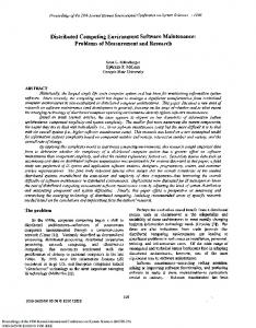
While in manual control all the 12 robot joints are moved. Motion Control in Pyro provides a unique abstraction to move the robot, regardless of the kind of drive mechanism. The available abstractions are “translate” and “rotate” of a given value. The values are not dependent on the motor drives, but are given in world coordinates. The Pyro library includes modules for various robot control paradigms, as direct control, finite state machines, subsumption architecture, fuzzy logic control, and neural network control. The vision modules provide a library of the most commonly used filters and vision algorithms. In the brain control, the next step is decided after a behavior, based on the result of the vision system, that keeps the robot out of obstacles. The behaviors are objects that inherits from the Brain class. A Pyro brain is required to have a step method that implements the decision procedure and is executed on every control cycle, which occur about 10 times a second. A Pyro brain also has a setup method that is called when the brain is instantiated. In Warugadar, to walk over obstacles or to avoid obstacles we developed a brain that integrates vision and information from the sensors in the feet. The autonomous behavior of the robot depends mainly on vision. The vision system uses the CMUcam arranged in the front of the robot and used to take a picture which must include part of the terrain [7, 8]. For efficiency, the lowlevel vision library code is written in C++. During the analysis the image is binarized to indicate in white the free space and in the black the part of the terrain including obstacles or blocked by obstacles. The basic hypothesis is that the floor has a uniform texture. Using statistical analysis we can extract from the picture of the floor the areas occupied by obstacles because they change the regular pattern. We see an example in Fig. 6. A simple behavior is that of moving away from black areas. During the movement the direction of walking can be modified by the brain, if it received
7
from data acquisition board no signals from piezoelectric sensors or a particular difference between the two sensors signal under the same leg. In this case, the brain stops the robot movement and manages the legs to rotate in order to find a stable position. Afterwards, the vision system analyzes the new position and the robot movement restarts.
Figure 6. The free space before obstacles is in white. The forbidden area in black.
5. Tests and conclusions The mechanical structure of Warugadar is simple and quite effective. Thanks to the light structure, the actuators are not pushed to their limit and as a result stability is good, movements are fast and well-executed, and it is possible for the robot to carry small loads without impacting the performance. Installation of piezoelectric pressure sensors and camera was successful, meaning that they are fully integrated with the rest of the system and the information they give is meaningful. Warugadar was conceived as a modular platform in both hardware and software, and it is relatively easy to add new features and capabilities, and properly integrate them with the existing architecture. The robot is a useful platform for robotics education; it has been developed by students and ir will serve students. The Pyro interface makes this robot a practical tool for the development of AI applications in many curricula.
8
References 1.
2.
3. 4. 5.
6. 7.
8. 9. 10. 11.
12. 13.
A. Abourachid. A new way of analysing symmetrical and asymmetrical gaits in quadrupeds. Comptes Rendus Biologies, 326, 625-630, July 2003. E. Callaway, P. Gorday, L. Hester, J.A. Gutierrez, M. Naeve, B. Heile, and V. Bahl. Home networking with ieee 802.15.4: A developing standard for low-rate wireless personal area networks. IEEE Communications Magazine, 40(8):70-77, August 2002. E. Callaway. Low power consumption features of the ieee 802.15.4/zigbee lr-wpan standard. In SenSys 03, November 2003. Measurement Specialties Inc. Piezo Film Sensors Technical Manual, April 1999. S. Chitta and J. P. Ostrowski. New insights into quasi-static and dynamic omnidirectional quadrupedal walking. Proc IEEE Intl. Conference on Intelligent Robots and Systems., October 2001. J.A.Cook and J.A.Vilensky. Do quadrupeds require a change in trunk posture to walk backward?, volume 33. J. of Biomechanics, March 2000 G. Gini, A. Marchi. Indoor Robot Navigation with Single Camera Vision, Proc. Pattern Recognition in Information Systems, PRIS, Alicante, Spain, April 2002 Horswill Ian, Polly: A Vision-Based Artificial Agent, Proceedings of AAAI-93, AAAI Press/The MIT Press. H. Jaffe, B. Jaffe, W. R. Cook Jr. Piezoelectric ceramic. Academic Press London and New York, 1971. C. Queiroz, N. Goncalves N., and P. Menezes. A study on static gaits for a four-leg robot. Proc. Int. Conference on Control, 2000. R. Musaloiu and A. Terzis. Minimising the effect of wifi interference in 802.15.4 wireless sensor networks. Int J of Sensor Networks, 3(1):43-54, January 2008. S. Ma, T. Tomiyama, and H. Wada. Omnidirectional static walking of a quadruped robot. IEEE Trans on Robotics, 21:152-161, April 2005. S. Choi Soo, Y. Shin, H. S. Park and W. Hyun Kwon. Packet error rate analysis of zigbee under wlan and bluetooth interferences. IEEE Trans on Wireless Communications, August 2007.