Available online at www.sciencedirect.com Available online at www.sciencedirect.com
Procedia Engineering 00 (2011) 000–000 Procedia Engineering 15 (2011) 720 – 724
Procedia Engineering www.elsevier.com/locate/procedia
Advanced in Control Engineering and Information Science
A new kind of numerical control method Liu Huran * , Lou Yi, Zhang Li Zhejiang University of Science and Technology
Abstract A new kind of numerical control system is presented in this paper. The main movement of the numerical control system is driven by the traditional power, such as hand wheel or hydraulic power。the movement is detected by an grating detector, or other detect devices and the displacement of the main movement is input to a computer simultaneously. finally the computer drives the other axis to move immediately, according to the preset program or rule. In this way, the NC system, for example, NC machining tool, can realize any kind of complex and powerful cutting or manufacturing at higher maching speed than other machines. With the higher power and speed servomotor or servo system expansiving, this system will fulfill working task with higher productivity and lower cost. © 2011 Published by Elsevier Ltd. Open access under CC BY-NC-ND license.
Selection and/or peer-review under responsibility of [CEIS 2011] key words: numerical, control software
1. Main text The transformation of the NC system on tool- grinder is studied in the paper ,and a precise theory is proposed in processing the special revolving cutter on the NC grinder. The circuit diagram of hardware interface and the NC software written in assembly language are also deliverd. Then,A new kind of numerical control system is presented in this paper; which is characterized by main movement with the traditional power-driven, grating detection and NC linkage. (Due to high power, high-speed servo motor system is expensive.) 1.1. The NC hardware circuits and software programming The Open-loop computer control tool grinder is a reconstructed one for the light universal tool grinding machine MQ6025A ,which is contolled by the Microcontroller MCS-51 and assembled the
*
Corresponding author: +8613857101626 E-mail address:
[email protected]
1877-7058 © 2011 Published by Elsevier Ltd. Open access under CC BY-NC-ND license. doi:10.1016/j.proeng.2011.08.134
2
LiuLiu Huran et al. / Procedia – 724 Huran et al/ ProcediaEngineering Engineering1500(2011) (2011)720 000–000
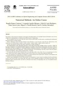
checking circuit , interface circuit , optoelectronic isolating circuit , power amplifying circuit , step motor drive circuit . the NC software of processing program of the small shaped cutter written in assembly language is stored in the MCS-51 EPRAM area,when the process is input the microcontroller, the grating detector output pulse to the CPU, CPU will subtraction the pulse sent from grating detector with a given pulse number . the step motor drives the workpiece to the corresponding displacement ψ according the program . When the pulse number of the step motor equivalent to the given number , the microcontroller immediately stop processing ,and automatically turn to next program and continue to control the processing. When the grating detector no longer output pulse to the microcontroller ,that means the workpiece processing is completed entirely, then the computer wait for the restart command and repeat the above process, this is the basic work process. The interface circuit shown in Figure 1. the interface.of the Stepper motor and computer . The power supply uses a high-voltage constant current chopper drive power. In Figure 1 ,the optocoupler VL1-VL3 is isolators, V2-V5 is a power transistor, V2 and V3, V4 and V5 are connected in Darlington form to improve magnification and drive capability. Rf is the feedback signal sampling resistor, W is the one phase winding in the step motor, VD3 is the continuous current diode. 74LS373 is 8 tri-state flip-flop, one output signal controls a phase winding,so it can control two triphase step motors. Q output high level, which will conduct one controlled phase winding . The LE in 74LS373 is the latch end where high level is effective.
721
722
Huran / Procedia Engineering 15 (2011) 720 – 724 Liu Liu Huran et alet/ al. Procedia Engineering 00 (2011) 000–000
Figure1 grating detector circuit Working process: it is set no current for the initial state of the winding, the volt drop on Rf is 0 , ie Uf = 0. Therefore, the optical coupler VL3 LED goes out, the phototransistor is off, it make one input terminal of D5 high level. If the terminal P0 of the 8031 output 01, WR is effective, and the 74LS373's LE is acted on through inverter, then the microcontroller output signal is latched to the output terminal, so , 1Q output high level signal. The stepping signals make the light-emitting diode of VL2 light through D2 ,and make the triode conducting, D4 output high level, which conduct the power transistor V4 and V5; on the other hand,signal is applied to D5 gate circuit, output low level, output high through the inverter D6, and act on D1 with 1Q, D1 output low level, so the light emitting diode of VL1 optocoupler lights, and the optical transistor conduct. Therefore, D3 output high level, V1 is off, which make high-voltage power transistors V2 and V3 conduct, the high voltage Ug act on the motor winding so that one phase of the step motor conduct. With the rise of the winding current, the volt drop (Uf)on Rf increases .when Uf increases to a certain extent, the LBD of VL3 light, so the optical transistor is on. Then D5 output the high level , D6 output low level, but D1 is not immediately closed to make V2, V3 off, instead to delay closing, it can be avoided that current fluctuations of the winding make V2, V3 off too many times to cause much more switching losses. If the High voltage transistor V2, V3 is shut off, then the winding is supplied by the low voltage power Ud. When the winding current decline, Uf is down, VL3 is off, if the1Q is still high level, then the high-voltage transistor V2, V3 conduction, the high-voltage power act on the winding again, so that the winding current rise. While rising to the setting data, Uf make V2 and V3 closed. The repeated on-off of V2 and V3, achieve the constant current chopping control of the winding current . 1Q output low-level, and V2-V5 are closed, the winding current discharge through VD3-Ug-ground-Ud-VD4-L circuit from the above, we know that the control on the speed and direction of the step motor can be realized as long as the 8031 output corresponding signals in accordance with the methods and frequency of the interface step motor 1.2. grating detect circuit the Circuit is shown in Figure 2. the function diagram : two optoelectronic components separate 1 / 4 Moiré fringe spacing, each will receive a electrical signal, u1, u2,whose difference is п / 2, after shapping,two square-wave signal obtained .when the grating moves ,the pulse obatained by u1 trough the ifferential circuit, is located on u2 ', ,t just as u2' is "1" level, so a count pulse is outputed trough Y1.
3
723
Liu Huran et Huran al. / Procedia Engineering 15 (2011) – 724 Liu et al/ Procedia Engineering 00720 (2011) 000–000
4
Figure 2 NC circuit diagram Table 1. the table of output state P0 port inMicro-controlled five-phase stepmotor: P0 port number The output state of step motor winding
P0.7
P0.6
P0.5
0
0
On-off mark
0 0 0 0 0
0 0 0 0 0
1 1 1 1 1
0.4
P
P0.3
P0.2
P0.1
E
D
C
B
P0.0 hexadeci mal digit A
0 0 0 0 1
0 0 0 1 0
0 1 0 0
0 1 0 0 0
1 0 0 0 0
0
21H 22H 24H 28H 30H
724
Huran / Procedia Engineering 15 (2011) 720 – 724 Liu Liu Huran et alet/ al. Procedia Engineering 00 (2011) 000–000
To achieve control of machining parts with a chip , the basic problem must be solved to receive and transmit pulse through software and hardware pulse Section headings.Program Description: The entrance of the Pulse is the 8031's P3.3 pin ,that is , the external signal interrupts INT1 and triggers input. Pulse is output and connected to the port P0.0 . total program: a interpolation operation is required as each 1mm moving along X direction in test. For the pulses equivalent is determined by processing precision ,p = 0.04mm, that is,as soon as the data (0.04mm)is measured by grating, a pulse is output. As we know that 25 pulse are output by grating while X move1mm. Choose mode 2. .the Initial value of T1 = 2 ^ 8-25 = 0E7H .Step motor control program (ring distributor program).The generation of Timing pulse: in economic CNC system, the Power-on sequence in the five-phase step motor is as follows.Above table shows, the five shot control model code is output, the timing pulse is delayed to generate to control motor movement., the step motor move one step while inputting Each pulse: the motion state of the stepping motor is controlled by pulse sequence, the pulse number n control the rotation angular displacement of the step motor. n = 360X/Hsp/i/a ,when X = 1mm; Hsp = screw lead; a = stepping angle. The Step motor control program would run.Turn stop code = 1. 2. Conclusions The special revolving tools are important machining tools which include the equal spiral angle taper cylindrical milling cutter , the ball nose end mill and the hardmetal carbide rotary burrs . the rotary burrs and the ball nose end mill are needs on the modern numerical controlling machine in machining complex curved surface .In recent years there is a trend that the demands for this kind of the tools have increased substantially ,in tools industry frontiers. the rotary burrs with special blades presented in this paper are firstly prposed at home and abroadl , Which represents the international advanced level of the special tools . a comprehensive approach is discussed in the paper ,which comprises a simple moulding method with 2 coordinate axes for special revolving tools ,retrofitting gear grinding in the universal tool grinding machine , hydraulic drive, the detector with rolling grating and the blending control . all of these new methods can increase efficiency and reduce the cost of processing . Essentially it is a new numerical controlling method. References [1] Fan Q. and DaFoe R., 2005: “Gleason Expert Manufacturing System (GEMS) Opens a New Era for Digitized Manufacturing of Spiral Bevel and Hypoid Gears”, World Manufacturing & Market (WMEN), 79(4), pp. 87-93. [2]Fan Q., DaFoe R., and Swanger J., 2006: ‘New Developments in Computerized Design and Manufacturing of Spiral Bevel and Hypoid Gears’, The International Conference on Mechanical Transmissions, Chongqing, China, pp. 128-133. [3]Litvin, F. L., Fan, Q., Fuentes, A. and Handschuh, R. F., 2001, “Computerized Design, Generation, Simulation of Meshing and Contact of Face-Milled Formate-Cut Spiral Bevel Gears”, NASA Report, /CR-2001-210894, ARL-CR-467.
5


![[PDF] A New Kind Of Science Full Books - Google Sites](https://m.moam.info/img/260x300/pdf-a-new-kind-of-science-full-books-google-sites_64785a2e097c4786708cba76.jpg)


![[PDF] A New Kind Of Science Stephen Wolfram Download Online](https://m.moam.info/img/260x300/pdf-a-new-kind-of-science-stephen-wolfram-download_6478597e097c474e708cb70c.jpg)

