A New Layout Synthesis for Leaf Cell Design Masahiro Fukui, Noriko Shinomiya, Toshiro Akino Semiconductor Research Center, Matsushita Electric Industrial Co., Ltd. Moriguchi, Osaka, 570 Tel: +81-6-906-4684 Fax: +81-6-906-3851 e-mail:
[email protected] Abstract--- We propose a new layout synthesis with 2-dimensional transistor arrangement and a spontaneous process of 2-dimensional compaction and local re-routing. The compaction enables jumping over objects, minimizing the number of contacts for wiring. We applied the layout synthesis to actual cell design and obtained comparable results to handcrafted design.
I. INTRODUCTION The recent advances and diversification in fabrication technology activate the strong requirement for designing leaf cell libraries in a quite short period with as little effort as possible. Establishing a strong physical synthesis procedure for the rapid technology changes toward deep sub-micron is in demand. The circuits of the cells are reusable in many practical situations. Transistor sizing[1] and layout synthesis take the main part of the physical synthesis. Our contribution is to propose an efficient algorithm for the layout synthesis process. Physical cell design is generally defined by a task of implementing the placement and wiring of the given circuit with minimum cell width for the given cell layout structure - i.e., standard cells, I/O cells, data path cells, etc. The structure profile includes the height of the cell, N-well width, location and width of power and ground lines, and constrains on the cell boundary and pins. Diffusion sharing of transistors is quite efficient if the shared parts are carefully selected. Layout compaction plays an important role of the layout synthesis. The mid 70s was the early stage of the compaction researches. Many symbolic data models, e.g., fixed grid[2], constraint graph[3], virtual grid[4], and compaction methods for those data models were proposed. Those compactors are categorized in one dimensional compaction since the direction of the movement is limited to either vertical or horizontal. Two dimensional compaction was applied by alternating process of one-dimensional compaction in both vertical and horizontal directions[4]. Dramatic improvement has been made by the appearance of true two-dimensional compaction[5-6] in the 80s. Shin and others' "Zone Refine"[6] method formulates the 2-
dimensional movements by an analogy of zone refining of a crystal ingot. The algorithm can escape from local dead lock that is found in one-dimensional compaction. However, the layout model was too simple and needs further work to apply it to actual cell design. It represents transistors with boxes and wires connected to some boxes. A model that expresses the diffusion share of transistors and cell structure is required. Additionally, a movement in which one layout element skips over another element has not been achieved by conventional compactors but it is quite an efficient movement to save the cell area.
Figure 1. Jumping over other layout elements to save area.
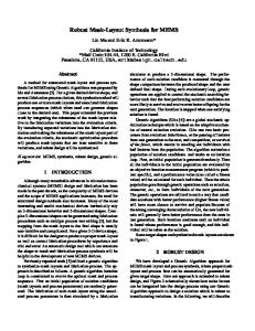
Finding a good transistor arrangement is another important role of the layout synthesis. Uehara et al.[7] proposed an elegant approach to the transistor arrangement in the early 80s. They, assuming P-type transistors and Ntype transistors are arranged in two rows respectively, formulated the transistor arrangement problem in C-MOS standard cell design with a graph algorithm. The objectives are maximizing the number of diffusion shares and finding a common linear sequence of n-transistors and p-transistors. Many cell synthesis algorithms[8-11] proposed after that followed the similar linear arrangement model. Unfortunately, the linear arrangement model has not been well accepted in practical cell design.[12] Main reason is that the area is not so minimized as hand-crafted design in many cases. Figure 2 is a small example showing the differences between a linear transistor arrangement model and
a hand-crafted design. Significant difference appears in their wiring area and dead space.
wiring channel
(a)
(b)
Figure 2. (a)Linear arrangement structure. (b) Hand-crafted design.
The figure 2(a) is a typical design produced by conventional linear arrangement design. Transistors are arranged in two rows and a channel router is used in the channel area between the two rows. The number of diffusion shares is maximized. The channel router uses poly-silicon line in vertical and aluminum line in horizontal. To the contrary, the figure 2(b) is a hand-crafted design example that ignores those restrictions of linear arrangement of transistors. It allows vertical arrangement as well as horizontal arrangement in both vertical and horizontal orientations. We call this free style transistor arrangement model 2dimensional transistor arrangement. A transistor is separated from shareable transistors and placed horizontally in the figure 2(b). This explains that maximizing the number of the diffusion share does not always solve the cell area minimization problem. The wiring layer rule is also ignored in the figure 2(b) to connect the wires with minimum number of contacts. A flexible router is essential as well as compaction and transistor arrangement. The routing region should be defined in the spaces between transistors. Maze based routers[13] or re-routers[14] deal with a detailed grid system where only one wire can go through a grid edge. Definition of the routing region with a channel graph or global wiring graph can be more flexible methods[15, 16]. The routing region is expressed with a set of graph edges. Each edge corresponds to a small channel that includes pins and wires going through the area. The channel router[17] or switch box router[18] is supposed to be used in each region. However, those routers tend to generate many contacts since a channel router uses different layer for the vertical and horizontal wiring. The number of contacts gives significant influences to the wiring area of cells. If we design a router that can be used in cell design, we should take the minimization of the number of contacts or trade-off analysis between detour of the wiring and generation of contacts into account. In this paper we propose: (1) an algorithm for finding a 2-dimensional transistor arrangement for standard cells when the height is limited, (2) a routing region definition and an algorithm of local routing, and a layout model for merged transistors, and (3) a new compaction method that enables jumping over elements by using the local router.
II. OUTLINE OF THE CELL SYNTHESIS Our cell synthesis system is composed of three main tools, (1) two-dimensional transistor arrangement, (2) local router, and (3) two-dimensional compaction with local rerouter. Input to the system is the circuit connectivity, transistors' size, and the cell height. The object function is to minimize the cell width. The 2-dimensional transistor arrangement determines the grouping of diffusion sharable transistors and 2-dimensional placement of those groups. To make the problem simple, we abstract each group of transistors with a rectangle and use a slicing structure[19,20] for the placement. The algorithm is implemented by exportation of the slicing structures and transistor grouping by simulated annealing [21]. The local router finds the symbolic wiring path of each net on virtual grids. The router analyzes the trade-off between the generation of contacts and detour wiring, and makes it possible to search limited length detour paths to avoid making contacts. The 2-dimensional compactor has re-routing capability. It can be executed after the diffusion shares and floor plan of transistors are determined, even if the wiring path has not been determined. The procedure includes cell structure definition with placement graphs, path finding in local part of the transistors and pins, and 2-dimensional movements of the layout elements. We discuss the detail algorithms in the following sessions. III. TWO-DIMENSIONAL TRANSISTOR ARRANGEMENT In the two-dimensional transistor arrangement, several floor plan techniques[19,20] can be applied to the size evaluation and definition of relative placement. Each element of the placement is abstracted with a rectangle that includes transistors grouped by diffusion sharing. T A A E
EF F BCD
B C D
B
(a)
(b) A
L
EF
R
BCD
(c)
Figure 3. (a) An example of slicing structure, (b) vertical polar graph, and (c) horizontal polar graph.
We use a slicing structure for the placement of the rectangles. It represents the relative placement of the abstracted groups. The height and width of the cell that is calculated by the longest path length of the horizontal and vertical polar graph[19]. An example is shown in figure 3. The goal of the algorithm is to find an optimum grouping of shareable transistors and an optimum slicing structure for the grouping. We used the simulated annealing method for the exploration in the space of the grouping of the transistors, and a greedy optimization for the slicing structure finding. The diffusion share condition is changed by local operations of grouping change.
time. At the point of grid vertex A, pre-determined wires P3 and P4 preclude the extension downward. Choices of the extension are limited to rightward and leftward. Next, assume that the router selected rightward for the next search. It adds a new wire-segment N2 and adds it between P2 and P4. The location of the new wire can be determined by the connection at grid vertex A. It gives a new wire-joint wjN2 at the grid vertex B. Then the router checks that wire P6 and P8 stop rightward movement at the grid vertex B, then it lists up upward and downward for the candidate direction of the next search. E1
E5
S
VI. LOCAL ROUTER
wirejoint
wire-segmen
grid edge
N1
P6
N3
P1
A. Data Structure
P7
P2
The local router uses a virtual grid model, but it doesn't have any limitation of the number of wires passing through a grid edge. The grid model is shown in the figure 4. Wires are connection of wire-segments and w i r e joints. The wire joint is located at any grid vertex where more than two wire-segments meet. Each transistor has three terminals(wire-joints) on both ends. Pins and contacts are placed on wire joints. Terminals of transistors, pins, and contacts have net identification. The routing process is to find a path for each net and to assign wire segments on each grid edge.
N2 E2
E7
E4
P3 P4
P5
E3
N4
grid vertex A
P8 grid vertex
serch direction pre-determined wires
Figure. 5.
E6
Searching mechanism on grids
grid vertices
B. Routing Algorithm Transistor
wire-joints grid edges gate
source
drain
(1) Net and Terminal Ordering
Pin
contact
wire
The procedure of path finding is used for initial routing as well as re-routing. The path finding process deals with tradeoff analysis between the length of detour and generation of contacts.
wire-joints
wire-joint wire-segment
First, the router determines net ordering, and terminal ordering for each net. Nets are arranged in the increasing order of half the perimeter of the area of the net terminals. Terminals of a net are arranged in an increasing order of the distance from the center of the area of the net terminals. It invokes the path finding process in the order of nets and terminals. (2) Path Finding
Figure. 4. Grid model
If more than one wire segment is located on one grid edge, the ordering of wires assigned to one grid edge is specified. The ordering makes path finding in the grid structure possible. Figure 5 depicts the mechanism of data structure with the example of finding a path from vertex S. Assume a new wire segment N1 is added to the left of P1 in grid edge E1. The router gives an ordering that N1 is placed left of P1. It adds a new wire-joint wjN1 to the grid vertex A at the same
The path finding process searches a wiring path from a specified terminal. The targets are pre-determined wires of the same net. The search is depth first search[13] basis and it finds the available search directions with the manner shown in the section A. First, it calculates the minimum manhattan distance from the start point to the targets. It has detour length as a penalty p. The initial value of the p is 0. It searches directions of moving closer to the targets. If no search is possible within the detour length of p, it increments the
value p and continues the search. Making a contact is also counted as a penalty length of detour to deal with the tradeoff analysis between the path length and generating contacts. pre-determined wire
S
AL
AL
A
D
B
E Figure 7. Transistor link by diffusion share.
C
F
B. Detailed Algorithm
PS contact
T
area searceh without detoue Figure 6. An example of path finding.
Figure 6 shows an example of the search. The start point and the target are S and T, respectively. Assume the penalty of making a contact is equivalent to two grids of detour. Grids reachable without detour are in the hatched area, and ones within detour of two are in the shadowed area. It shows there is no path to the target within the detour of two. Since the penalty of making a contact is equivalent to two, it searches grids closer to the target T that is reachable by making a contact. Grids, A, B, C, D, E, and F are also the candidates of searched grids within the penalty 2, and the path is found at this penalty level. IV. COMPACTION ALGORITHM
This session explains the each step of compaction algorithm in the sequence of the procedure flow. The statements between "/*" and "*/" are explanations, and other part is operation. Transistor, pins and contacts are the placement objects. Procedure (Step 1: Initialization) Initialize envelope as the left edge of the cell; (Step 2: Placement Graph Construction) Construct placement graphs for both vertical and horizontal; Add design rules to each edge as the weight; To define the cell structure, add vertices Sp, Dn, that correspond to the top and bottom edge of the cell; Add Sn and Dp that correspond to the center division; Add vertices L, R that corresponds to the left and right edge of the cell, respectively; /* Figure 8 shows the structure of standard cells and placement graphs to represent the cell structure. If pins are required to be placed at the center of the cell, give edges from source Sp to the pins and from pins to drain Dn. */
Transistors and pins are subject to move in the compaction process. The features of our algorithm are: (1) dealing with shared transistor model, and (2) making element jumping over possible.
Power li Sp P type trans
Bp
Bp Ap Ap
Cp
Ap
N-well Sn
A. Transistor Model
Cp
Dp
R
L N type Transis An
The compactor deals with diffusion shared transistors as a placement element. The model enables each transistor's sliding, depending on the neighbor elements' placement.(see Figure 7).
Bp
Cp
Cn
Bn
Bn x-grap
An
An
Cn
Bn
Cn
Dn y-grap Ground li
(a)
(b)
(c)
Figure 8. (a) Structure of a cell, (b) vertical placement graph, and (c) horizontal placement graph.
Move all pin and transistor objects in G and wires produced in the step 4.3 to the left edge; Renew the envelope which covers all placed elements;
dist_s(A) S
dist_s(C) A
A
G
placed elements C
C B dist_d(A)
T
B
dist_d(C)
sum of placement probability
Figure 9. Placement density representation.
(Step 3: Placement Density Definition) Define the placement density representation; /* Vertical location of each object is limited by constraints given by the longest path length from Sp and to Dn. We define the placement probability is multiple of the object area size and the probability that is highest at the center of the placeable area. The placement density representation is sum of the placement probability for all objects. */ (Step 4: Placement of objects) Repeat the following until all placement object are placed; (Step 4.1: Finding a set of locatable objects ) Among un-placed objects, find a group S of objects that can be placed to the left; /* The objects correspond to vertices whose out-edges connect only vertices of placed objects. */ Process A: Select a vertex in S according to the priority; Place it to the smallest density zone of the temporal grids; /* At this stage, vertical placement of diffusion shared transistors are determined separately, but the movement is limited so that the transistors share their diffusion area */ (Step 4.2: Local placement to temporal grid ) For all object in the group S, define priority P(v) of object v with the formula, P(v) = A * dist_l(v) - dist_r(v), where A >> 1, dist_l(v) and dist_r(v) are longest path length in horizontal placement graph of v to L and R to v, respectively; Construct temporal grids as shown in figure 10; Continue the process A until no element can be placed to the left edge; Let G be the selected set of vertices at this step; (Step 4.3: Local re-routing at the temporal grid ) Remove the wiring path of the nets concerning to the objects in G, and invoke the local router for those nets; (Step 4.4: Stacking object to left edge )
envelope
floor
temporal grids
Figure 10. Compaction scheme.
V. EXPERIMENTAL RESULTS Table I shows experimental results. The column of "width of HCD" is value of the width of hand-crafted design. Figure 11(a) is a symbolic layout after the 2-dimensional transistor arrangement and the local routing. This does not maximize the number of diffusion share but achieve the minimum width. If it were implemented by conventional linear arrangement method, the width could have been 6. Figure 11(b) is a layout after our 2-dimensional compaction. The diffusion shared transistors are located at suitable place to make the wiring easy. Figure 12 is the synthesis results. Those results demonstrate that our cell synthesis is successfully applied to actual design and achieves the comparable level of a hand-crafted design. TABLE I EXPERIMANTAL RESULTS circuit height (unit) A B C D E F *HCD:
width (unit)
width of HCD* 16 5 5 12 4 4 16 4 4 16 7 7 16 4 4 16 7 7 hand-crafted design
# of dif. share 4 2 2 8 2 4
#of max. share 6 2 4 8 2 4
cpu time (sec) 2.5 1.0 1.6 2.7 1.0 2.1
ACKNOWLEDGEMENTS The Authors would like to acknowledge Director Takemoto and Dr. Kuninobu of Semiconductor Research Center for their supporting and encouraging our research. REFERENCES
(a)
(b)
Figure 11. (a) Symbolic layout and (b) compaction result of circuit A.
(a)
(b)
Figure 12. (a) Synthesized layout of circuit B and (b) D.
VI. CONCLUSIONS We proposed a new cell synthesis. This paper proposes the first approach to the 2-dimensional transistor arrangement. The experimental results show that the optimization goal of cell synthesis is not a maximization of the number of diffusion shares but an optimization of the 2dimensional arrangement of transistors. We also proposed local router and compactor that are most suitable for the 2-dimensional transistor arrangement. The local router has a new concept of the trade-off analysis between a detour wiring and insertion of a contact. The local re-routing aspect in compaction makes it possible for some elements to jump over other elements to save the cell area. The cell synthesis, by achieving comparable level of a hand-crafted design, may change the future design stile of a block or chip layout. For example, a dynamic cell synthesis including a merging process of neighbor cells in the phase of a placement or global wiring was proposed recently.[22]
[1] Neil H. E. Weste and Kamran Eshraghian, "Principles of CMOS VLSI Design: A Systems Perspective," Addison-Welsey Publishing, pp.196-201, 1985. [2] D. Gibson and Scott Nance, "SLIC - Symbolic Layout of Integrated Circuits," Proceedings of the 13th Annual Design Automation Conference, Jane 1976, pp.434-440. [3] M. Y. Hsueh and D. O. Pederson, "Computer-Aided Layout of LSI Circuit Building-Blocks," Proceedings of 1979 IEEE International Symposium on Circuits and Systems, pp.474-477. [4] N. H. E. Weste, "Virtual Grid Symbolic Layout," Proc. 18th Design Automation Conference, June 1981, pp.225-233. [5] W. Wolf, J. Newkirk, and R. Dutton, "Two-Dimensional compaction Strategies," IEEE International Conference on Computer Aided Design, pp.90-91, Sept. 1983. [6] H. Shin, A. Sangiovannni-Vincentelli, "Two dimensional compaction by 'Zone Refining'," 23rd DAC, pp.115-119, 1986. [7] T. Uehara and W.M. VanCleemput, "Optimal Layout of CMOS functional arrays," IEEE Trans. Computer vol.-30, pp.305-312, May 1981. [8] A. Domic, S. Levitin, N. Phillips, C. Thai, T. Shiple, D. Bhavsar, C. Bissell, "CLEO: a CMOS Layout Generator," ICCAD89, pp.340-343, 1989. [9] C-Y. Hwang, Y-C Hsieh, Y-L Lin, Y-C Hsu, "An Optimal Transistor-Chaining Algorithm for CMOS Cell Layout," ICCAD89, pp.344346, 1989. [10] S. Wimer, et al., "Optimal Chaining of CMOS Transistors in a Functional Cell," IEEE Trans. CAD, Vol. CAD-6, No. 5, Sep. 1987. [11] C. J. Poirier, "Excellerator: Custom CMOS Leaf Cell Layout Generator," IEEE Trans. CAD, pp.744-736, 1989. [12] M. Fukui and T. Akino, "An Algorithm for VLSI Leaf Cell Generation," VLSI Design Tech., Report VLD94-65, Oct. 1994.(in Japanese) [13] F. O. Hadlock, "A Shortest path Algorithm for Grid Graphs," Networks, 7, pp.323-334, 1977. [14] H.Shin and A. Sangiovannni-Vincentelli, "MIGHTY: A `Rip-up and Re-route' Detailed Router," Proc. 1986 Int. Conf. on CAD, pp.2-5, Nov. 1986. [15] S. Tsukiyama, I. Harada, M. Fukui, and I. Shirakawa, "A New Global Router for Gate Array LSI.," IEEE Trans. on CAD Vol.CAD-2, No. 4, Oct. 1983. [16] W. M. Dai, T. Asano, and E. S. Kuh, "Routing Region Definition and Ordering Scheme for Building Block Layout," IEEE Trans. on CAD of ICAS, Vol. CAD-3, no. 3, pp.218-225, July 1984. [17] T. Yoshimura and E. S. Kuh, "Efficient Algorithms for Channel Routing," IEEE Trans. on CAD of ICAS, pp.25-36, Jan. 1982. [18] T. G. Hamachi and J. K. Ousterhout, "A Switch-box Router with Obstacle Avoidance," Proc. 21 nd Design Automation Conf., pp.173-179, Jun. 1984. [19] R. Otten, "Automatic Floor-plan Design," Proc.19th Design Automation COnf., pp.261-267, June 1982. [20] D. Wong and C. Lin, "A New Algorithm for Floor-plan Design," Proc. 24th Design Automation Conf., pp.101-107, June 1986. [21] S. Kirkpatrick, C. D. Gelatt and M. P. Vecchi, "Optimization by Simulated Annealing", Science, Vol. 220, N.4598, pp.671-680, May 1983. [22] N. Shinomiya, M. Fukui, and T. Akino, "A New Sea-of-Cells Style Layout Architecture," VLSI Design Tech., Report VLD94-99, pp.45-52, Mar. 1995.(in Japanese)