based RDB to RDF/OWL mapping approach that is based on defining correspondence between the tables of the database and the classes of the ontology, ...
Special Issue of International Journal of Computer Applications (0975 – 8887) on Software Engineering, Databases and Expert Systems – SEDEXS, September 2012
A New Method for Mapping UML Class into OWL Ontology Noreddine Gherabi
Mohamed Bahaj
Hassan 1 University, FSTS Department of Mathematics and Computer Science
Hassan 1 University, FSTS Department of Mathematics and Computer Science
ABSTRACT In this paper we describe how UML schemes can be converted into OWL Ontology, thus enabling reasoning on them by Semantic Web applications. The proposed solution is based on a three phases approach, the first step is to present the class diagram in the mathematical formulation and the second one is converting the UML Class into encoded text file, finally, the structure of the classification scheme is converted into OWL ontology. We demonstrate the practical applicability of our approach by showing how the results of reasoning on these OWL ontology can help improve the Web systems.
Keywords- component; RDF, OWL, Web ontologie,UML 1.INTRODUCTION This document aims to define a correspondence between the class diagrams of Unified Modeling Language (UML) [1] and OWL using the mathematical representation of the class diagram. The OWL Web Ontology Language [2] is designed for use by applications that need to process the content of information instead of just presenting information to humans. The use of ontology Web is growing rapidly since the emergence of the Semantic Web. Most of the data is still modeled and stored in relational databases / objects and therefore out of reach for many applications of the Semantic Web. A critical requirement for the evolution of the current Web of documents into a Web of Data is the inclusion of the vast quantities of data stored in Relational Databases (RDB). The mapping of these vast quantities of data from RDB to the Resource Description Framework (RDF) has been the focus of a large body of research work in diverse domains. Some of the most notable approaches of this kind are R2O [3], D2RQ [4], Virtuoso RDF Views [5, 6] and DartGrid [7]. The R2O approach defines declarative and extensible language (in xml) to describe mapping between given RDB and an OWL ontology or RDFS schema so that tools can process this mapping and generate triples that correspond to source RDB data. G.Bumans et al [8] demonstrate a very simple standard SQLbased RDB to RDF/OWL mapping approach that is based on defining correspondence between the tables of the database and the classes of the ontology, as well as between table fields/links in the database and datatype/object properties in the ontology. UML models cannot be easily exchanged over the Web, the reasoning possibilities with UML models being also quite restricted. [9] and [10] propose a simples transformations between UML and ontology representation languages. Recently, some efforts arose in bringing together UML and the Semantic Web. Nevertheless, most of these approaches do not use all proprieties of the UML diagrams as a data source.
In this direction several researches are underway to transform data into Web semantic (XML/RDF/OWL). J. Fong et al [11] proposes a method for Converting relational database into XML data with DOM. Wu and Hsieh [12] used a technique for mapping UML to XML. They created XSD from class diagrams, but this technique is very complex to generate the XSD file for each class diagram. In our previous work [13], we have developed a Framework for converting a class diagram into an XML document and show how to use Web files for the design of data based on the classification UML. Our approach for mapping is based on several steps. First step is to formulate the class diagram into a mathematical structure and transform it into an encoded text file (Section II). After the text file is imported into the system to build the structure of OWL diagram using the algorithm called GenarateOWL described in Section III, and finally the exported OWL file will be validated and stored
2.UML FOR THE SEMANTIC WEB A. Mathematical representation of UML Class. Modeling Layer allows the representation of the UML model into a logical representation. For this task, we have applied a mathematical approach for semantically enriching of the UML Model. In our approach, a class diagram in UML is represented as a set of classes, denoted as 4-tuple:
UML C : C C : (C N ,C A , CO , C R
Where:
CN :
is the name of the class C.
CA :
is the list of attributes associated with this particular
class
C A : A A : ( An , At , Av , Ad
Av is the visibility of this attribute (Public, Private or protected) and Ad is Where
An
is an attribute name,
At
is its type,
a default value if given.
C O : is a set of operations for defined class C
CO : O O : (On ,Ot , Ov )
5
Special Issue of International Journal of Computer Applications (0975 – 8887) on Software Engineering, Databases and Expert Systems – SEDEXS, September 2012 Where
On is
the name of the operation O ,
Ot
its type and
-
Inheritance: There are in any OWL ontology a superclass named “Thing”, which all other classes are subclasses. With rdfs:subClassOf we can specify a class C1 to be subclass of another class C2; then every instance of C1 is also an instance of C2.
Ov is the visibility of this operation.
C R : describes the different types of relations that can exist between any pair of classes in the UML diagram.
For example, consider the class C1 inherits from C2, the Web Ontology representation is as follows:
owl : Class rdf : ID " C1 R tag "
C R : R R : ( Rt , Rc , Rs , Rtag ) Rt is the type of relationship (Association, Composition, Aggregation or Generalization), Rc is the cardinality specified for the source class, R s is a source class and Rtag defined the Where
rdfs : subClassOf rdf : resource " # C2 Rs" / /owl : Class -
Mapping cardinality: The cardinalities of a relationship are given by specifying minimum and maximum cardinalities. For mapping the general cardinality we use:
target class with which the source class is connected.
owl : cardinalit y rdf : datatype"&xsd, nonNegativ eInteger"
B.Mapping process
Cardinality Rc /owl : cardinalit y
We now define the sets to describe the structure ontology Web. When the structure of UML has been obtained, the schema translation starts by applying an appropriate set of rules to map the UML constructs into Web ontology. The mapping process is done progressively as follows: It starts by mapping the classes of the diagram to OWL classes, then mapping the attributes of each class to data type properties and the relationships into Object type properties. The mapping process consists therefore of the following steps: -
Each class in the class diagram is translated to owl:class in the Web ontology, a class in OWL technology is represented as follows:
< owl : Class rdf : ID ="C C N " / > -
Translating attributes: Each attribute A is translated into a owl:DatatypeProperty class and represented as :
owl : DatatypeProperty rdf : ID " A C A "
And for mapping the maximal cardinality of each relationship we use this syntax:
owl : maxCardina lity rdf : datatype"&xsd, nonNegativ eInteger" Cardinality Rc /owl : maxCardina lity
3.ALGORITHM FOR GENERATION OF OWL SCHEMA This subsection presents the GenerateOWL algorithm. Given an UML Class as input, the algorithm goes through a main loop to classify UML Class constructs and generate their equivalents in Web Ontologie Algorithm GenerateOWLs Input : UML Class OutPut: OWL Structure
rdfs : domain rdf : resource " # C UM L - C" / rdfs : range rdf : resource "&xsd, Type A t " / /owl : DatatypeProperty -
UML Class relationships are translated and defined among Web Ontology based on its type as association, aggregation, composition and inheritance. The association, aggregation and composition are transformed into owl:ObjectProperty class
For example: Consider the relationship between two classes C1 and C2, the representation of the relationship in Web ontology is represented as follows:
owl : ObjectProperty rdf : ID " Rel C R " rdfs : domain rdf : resource " # C1 UM L - C" / rdfs : range rdf : resource " # C 2 UM L - C" / /owl : ObjectProperty
CodifyDiagram() // a sub-function to codify the structure of the class diagram in a text file
ValidateClassDiagram() // this function verify the structure of the diagram and then validate it
GenerateOWLSchema()//generate all elements of the diagram and create a valid OWL file
ValidateOWLDocument()//validate the generated OWL file
END. The structure of the OWL generated by the algorithm corresponds to the UML class where each tag OWL is generated for each Class, each attribute and each relationship. In our algorithm the operations are not mapping.
B.
Codification of the diagram
In our approach the class diagram is codified in a symbolic form as follows:
6
Special Issue of International Journal of Computer Applications (0975 – 8887) on Software Engineering, Databases and Expert Systems – SEDEXS, September 2012
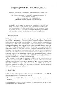
After, the system converts the encoded text file of our diagram into OWL-schema based on the series of rules, and then converted to an element OWL representing all proprieties of the diagram. The ontological concept is an explicit specification of a Figure 1. Example of Class Diagram conceptualization, they are often considered as graphs CN ; Number-of-Attributes ; {CA}/(An:At:Av:Ad);} ; Number-of-Operations ; {Co}/(On:Ot:Ov);} ; Number-ofRelationships ; {CR}/(Rt:Rc:RS; Rtag);}; For example: Consider the class “Employee” codified as:
Employee;3;Code:int:Public:;Name:String:Public:;Sal ary:Int:Protected:;1;getSalary:int:public;2;1..*:Comp any;1..*:Manager;0;0;0; In this example the class "Employee" is defined by three attributes: "Code" is the Int type, its visibility is public and its default value is undefined, same, the attribute "Name" is defined by the type String, with visibility Public and no default value, the 3rd attribute "Salary" its type is Int, visibility is protected and no default value. Class "Employee" contains a single operation "getSalary" the type of the return value is Int and its visibility is Public.
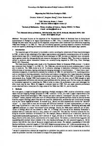
whose nodes represent concepts and whose directed edges represent the formal relations between the concepts. The basic graph structure of our example ontology is a taxonomy in which all classes are represented by nodes and relation between nodes represent an attribute, association, composition or inheritance relationship. Figure 2 illustrates the OWL structure of our example. The global mapping of the diagram is as follows:
Two association relationships that exists with the classes "Company" and Manager its cardinality is 1...*.
This representation is not sufficient, because the OWL structure should map all elements of the UML diagram.
C.
The representation of relationships in WEB ontology, mapping from UML class, is defined as:
Mapping OWL File
Consider a class diagram modeling of employees in a company, developed using MyEclipse, is shown in Fig. 2. This model will be used in the examples presented along the paper. The encoded text file that contains the structure of the diagram is defined as follows: Employee;3;Code:int:Public:;Name:String:Public:;Salary:Int:Prot ected:;1;getSalary:int:public;2;1..*:Company;1..*:Manager;0;0;0; Company;2;Name:String:Public:;Adress:String:Public:;2;getNam e:string:Protected;getAdress:string:public;1;1..1:Employee;0;0;0; Unit;2;Number:int:Public:;Name:String:Public:;2;getNumber:int: Private;AddNewUnit:string:Public;0;1;1..*:Company;0;0; Manager;1;Task:string:Private:;1;AddTeamManager:String:Publi c;2;1..1:Employee;0;0;1;Employee;
7
Special Issue of International Journal of Computer Applications (0975 – 8887) on Software Engineering, Databases and Expert Systems – SEDEXS, September 2012
Code DatatypeProperty
Task
SubClassOf
ObjectProperty
Manager
Name
Employee Salary ObjectProperty
Name
Subclass Company "Manager" of "employees" having an association DatatypeProperty relationship with it, according to cardinalté 1, and is represented Unit in an ontological structure as follows: ObjectProperty Number DatatypeProperty Adress Name 1
In summary, the main contributions of this paper are listed as follows. Firstly, we have presented a new approach to discovering simple mapping between classes in UML diagram and ontology. The system captures the semantic structure contained in the UML Classes and eliminates incorrect mappings by validating mapping consistency. Secondly, we have proposed a novel algorithm to construct contextual mappings, the algorithm reuse simple mappings between UML and web ontology.
4. CONCLUSION In this paper, we present an efficient technique for generate an OWL structure from UML design. We analyze the existing transformation techniques using all the analysis parameters identified. We have experimentally evaluated our approach on several examples of UML classes; the results show that the contextual mappings constructed by our approach are useful and meaningful.
5.REFERENCES [1] M. Fowler and K. Scott, UML Distilled, 2nd Edition, Addison Wesley, Boston, 2000. [2] Tim Berners-Lee, James Hendler, and Ora Lassila. The Semantic Web. Scientific American, May 2001. [3] J. Barrasa, A. Gómez-Pérez. Upgrading relational legacy data to the semantic web. In: Proc. of the 15th International World Wide Web Conference (WWW 2006), Edinburgh, United Kingdom, 23–26 May 2006,pp. 1069–1070.
8
Special Issue of International Journal of Computer Applications (0975 – 8887) on Software Engineering, Databases and Expert Systems – SEDEXS, September 2012 [4]
D2RQ Platform. Available: http://www4.wiwiss.fuberlin.de/bizer/D2RQ/spec/.
[5] C. Blakeley. RDF Views of SQL Data (Declarative SQL Schema to RDF Mapping). OpenLink Software, 2007.
[10] A. Felfernig, G. Friedrich, and D. Jannach. UML as domain specific language for the construction of knowledge based configurations systems. International Journal on Software Engineering and Knowledge Engineering, 10(4):449–470, 2000.
[6]
OpenLink Virtuoso Platform. Automated Generation of RDF Views over Relational Data Sources. Available: http://docs.openlinksw.com/virtuoso/rdfrdfviewgnr.html.
[11] Fong, J. H.K. Wonga, Z. Cheng, Converting relational database into XML documents with DOM. Information and Software Technology. v45. 335-355,2003.
[7]
W. Hu, Y. Qu. Discovering Simple Mappings between Relational Database Schemas and Ontologies. In: Proc. of the 6th International Semantic Web Conference (ISWC 2007), 2nd Asian Semantic Web Conference (ASWC 2007), Busan, Korea, 11–15 November 2007, LNCS, 4825, pp. 225–238.
[12] I-Chen Wu, Shang-Hsien Hsieh; “An UML-XML-RDB Model Mapping Solution for Facilitating Information Standardization and Sharing in Construction Industry”; Proceedings. National Institute of Standards and Technology, Gaithersburg, Maryland. September 23-25, 2002, 317-321 pp
[8] Mapping between Relational Databases and OWL Ontologies: an Example Computer Science and Information Technologies. Vol. 756 99–117 P. (2010)
[13] Noreddine Gherabi and Mohamed Bahaj. Robust Representation for Conversion UML Class into XML Document using DOM. International Journal of Computer Applications 33(9):22-29, November 2011
[9] K. Falkovych. Ontology Extraction from UML Diagrams. Master’s thesis, Vrije Universiteit Amsterdam, August 2002.
9