Int. J. Nav. Archit. Ocean Eng. (2015) 7:142~156 http://dx.doi.org/10.1515/ijnaoe-2015-0011 pISSN: 2092-6782, eISSN: 2092-6790
ⓒ SNAK, 2015
A new method for ship inner shell optimization based on parametric technique Yan-Yun Yu1,2, Yan Lin1,2, Ming Chen1,2 and Kai Li1,2 1
State Key Laboratory of Structural Analysis for Industrial Equipment, Dalian University of Technology, Dalian, China 2 Ship CAD Engineering Center, Dalian University of Technology, Dalian, China
ABSTRACT: A new method for ship Inner Shell optimization, which is called Parametric Inner Shell Optimization Method (PISOM), is presented in this paper in order to improve both hull performance and design efficiency of transport ship. The foundation of PISOM is the parametric Inner Shell Plate (ISP) model, which is a fully-associative model driven by dimensions. A method to create parametric ISP model is proposed, including geometric primitives, geometric constraints, geometric constraint solving etc. The standard optimization procedure of ship ISP optimization based on parametric ISP model is put forward, and an efficient optimization approach for typical transport ship is developed based on this procedure. This approach takes the section area of ISP and the other dominant parameters as variables, while all the design requirements such as propeller immersion, fore bottom wave slap, bridge visibility, longitudinal strength etc, are made constraints. The optimization objective is maximum volume of cargo oil tanker/cargo hold, and the genetic algorithm is used to solve this optimization model. This method is applied to the optimization of a product oil tanker and a bulk carrier, and it is proved to be effective, highly efficient, and engineering practical. KEY WORDS: Ship; Inner shell plate; Optimization design; Parametric; Genetic algorithm.
SYMBOLS AND ABBREVIATIONS SISOM SWBM CH WBT DWT
Ship Inner Shell Optimization Method Still Water Bending Moment Cargo Hold Water Ballast Tank Deadweight
ISP PISOM COT GA
Inner Shell Plate Parametric Inner Shell Optimization Method Cargo Oil Tank Genetic Algorithm
INTRODUCTION Subdivision is a decisive factor for the performance of transport ships such as oil tanker and bulk carrier. First of all, those ships should have sufficient Cargo Oil Tank (COT) or Cargo Hold (CH) volume for their design mission, and the centroid of CHs/COTs should meet the flotation requirements. Under each sea going condition, the aft draft of the hull should Corresponding author: Yan-Yun Yu, e-mail:
[email protected] This is an Open-Access article distributed under the terms of the Creative Commons Attribution Non-Commercial License (http://creativecommons.org/licenses/by-nc/3.0) which permits unrestricted non-commercial use, distribution, and reproduction in any medium, provided the original work is properly cited.
- 10.1515/ijnaoe-2015-0011 Downloaded from PubFactory at 08/10/2016 01:28:20AM via free access
2
Int. J. Nav. Archit. Ocean Eng. (2015) 7:142~156
be deep enough in order to guarantee propeller and rudder efficiency (Chen et al., 2010a), and that’s why most of the ships navigate with significant aft trim under light load conditions. However, the aft trim should not be too large. Otherwise, the ship may have poor seaworthiness or bad bridge visibility. As a result, all the conventional transport ship should have enough Ballast Water Tank (WBT) capacity for the flotation requirement. All the transport ships should satisfy the safety requirements of damage stability (IMO, 2004) as well as longitudinal strength (IACS, 2006a; 2006b), and both damage stability and longitudinal strength are closely related to subdivision scheme. In additional, ship subdivision should satisfy different requirements for different kind of ships. For instance, the arrangement of COTs for oil tankers should meet the requirement of pollution prevention (IMO, 2002); as to most the bulk carriers and oil tankers, the shape of CHs/COTs should be convenient enough for unloading and sweeping operation. Therefore, it is an efficient way to improve the safety and economy performance of ship via subdivision optimization. Generally, ship subdivision optimization methods could be divided into two categories: bulkhead optimization and Inner Shell Plate (ISP) optimization. In the previous literatures, some researchers proposed different methods to improve the performance of ship by bulkhead optimization. Ölçer et al. (2006) integrated multi-objective optimization with bulkhead positions as variables, and developed a multiple criteria decision-making methodology to optimize design of the Ro-Ro ships. Ivanov et al. (2007) proposed a simplified sheer force and bending moment calculating method and applied it in ship subdivision optimization with bulkhead positions as variables. George et al. (2008) developed a systematic sensitivity analysis of bulkhead number, bulkhead positions for RoPax vessels to improve the damage stability. Chen et al. (2010b) proposed a tank subdivision optimization method to minimize the bending moment under sequential ballast water exchange conditions. The methods of bulkhead optimization are efficient to improve some of the ship performance, such as damage stability, ballast water exchange efficiency etc. However, those methods could not improve some other performance that may be more important to ship economy and safety, such as increasing CH/COT volume, decreasing the maximum Still Water Bending Moment (SWBM) in full load or normal ballast conditions etc. That’s because the determining factor of CH/COT volume and longitudinal strength in full load or normal ballast condition is not the bulkhead number or bulkhead positions, but the shape of ISP. Since ISP is of great importance to the general performance of transport ships, it is an efficient way to improve the hull performance through ISP optimization. Yu and Lin (2013) proposed an ISP optimization method (called SISOM) to improve the safety of transport ship. SISOM has been proved to be efficient to improve the ship safety by reducing the maximum SWBM. However, SISOM takes the section areas of ISP at knuckle position as optimization variables, so it could not optimization the longitudinal dimensions of ISP such as longitudinal knuckle position, which are also important factor to the hull performance. Besides, in SISOM the gradient-based method is used to solve the optimization model, which means SISOM could only find the local optimum solution. Aiming at that problem, a new method for ISP optimization of the transport ship, called Parametric Inner Shell Optimization Method (PISOM), is presented in this paper. Being different from SISOM, PISOM takes both section dimensions and longitudinal dimensions as design variables, and Genetic Algorithm (GA) is used to solve the optimization problem. PISOM could find the better solution than SISOM theoretically, but the ISP model of PISOM is much more complex, so parametric modeling technique is introduced to generate ISP model in PISOM. The paper is organized as follows. Firstly, the systematic method of creating parametric ISP model is proposed in section 2. The optimization model for PISOM is introduced in section 3, and the solving strategy with GA is described in detail in section 4. In section 5, PISOM is applied to a 50000 DWT product oil tanker and a 175000 DWT bulk carrier. Section 6 is a brief conclusion of PISOM.
PARAMETRIC ISP MODEL In the conventional ship design method, ISP is designed by the 2D ISP knuckle point position drawing (ISP knuckle drawing for short), as shown in Fig. 1. ISP knuckle drawing contains all the ISP geometric data in the form of curves or dimension annotations. The dimensions in the annotations are the optimization objects of PISOM. However, ISP optimization could
- 10.1515/ijnaoe-2015-0011 Downloaded from PubFactory at 08/10/2016 01:28:20AM via free access
Int. J. Nav. Archit. Ocean Eng. (2015) 7:142~156
3
not be carried out base on ISP knuckle drawing. Firstly, there are quite a lot of redundant data in ISP knuckle drawing, which is to say the curves in this drawing should meet quite a lot of implied requirements, such as equal length, parallel, symmetry etc. Any modification without exactly consideration of those implied requirements will cause unreasonable result. Secondly, the dimensions in this drawing should meet various hull performance requirements, such as flotation, longitudinal strength and pollution prevention, while it is hard to calculate the hull performances according to ISP knuckle drawing. ISP optimization requires a powerfully ISP model, which is driven by dimensions and all the geometric constraints as well as hull performances constraints could be maintained or checked conveniently.
Fig. 1 Typical ISP knuckle point position drawing. As is known, dimension-driven is the most important characteristic of parametric design method, which is widely used in the current CAD, CAE and CAM field. In parametric design method, the parameterization is realized by the sketch, which is a 2D drawing with constraints. When the dimension is modified, the geometry will be changed by geometric constraint solving to satisfy all the constraint requirements. Parametric design is the most commonly used geometric modeling method at present, and Yu et al. (2010) had successfully introduced this method into platform general design as well as ship structure finite element analysis (Yu et al., 2009). However, none of the existing parametric methods could be used in ISP parametric design, for ISP is a complex spatial boundary plane model. Aiming at this problem, a new method to create the parametric ISP model is developed as follows.
ISP sketch ISP sketch is the foundation of ISP model, and it is mainly composed of geometric primitives and geometric constraints. ISP is a spatial 3D shell with several transverse corners, and the sections at different corner position are related to each other rather than being independent. The relationships between sections at different corner position results in that it is infeasible to indicate the longitudinal geometric data with text annotations. So, as shown in Fig. 2(a), ISP sketch consists of two views. The right one is the transverse view, which is similar to ISP knuckle drawing. The left one is the profile view, which is used to manage the longitudinal position data and relationships between each transverse section. In the transverse view, the fore part and aft part are drawn in the right and left side respectively in order to make the drawing more readable. The longitudinal coordinates of the profile view is scaled by 0.2 so that it is easy to be managed.
- 10.1515/ijnaoe-2015-0011 Downloaded from PubFactory at 08/10/2016 01:28:20AM via free access
4
Int. J. Nav. Archit. Ocean Eng. (2015) 7:142~156
(a)
(b) Fig. 2 Typical ISP sketch of the transport ship. The constraints in ISP sketch could be divided into two categories, topology constraints and dimension constraints. Topology constraints are used to control the shape of the sketch, and dimension constraints are used to specify the size of ISP. Fig. 2(a) is the topology constraints drawing, and Fig. 2(b) is the dimension constraints one. Actually, topology constraints and dimension constraints are in the same sketch, and they are separated and shown in Fig. 2(a) and 2(b) just for better readability. Fig. 2 looks like a 2D drawing with dimensions. However, it is far more than a 2D drawing. First, it contains all that a 2D drawing has, such as precise geometries, readable text dimensions etc. More importantly, the dimensions in ISP sketch are constraints, which could be used to drive the shape of the drawing. The topology constraints ensure the correctness of the topology among the geometric primitives when the value of any dimension constraint is changed. There are three elements for the sketch, which are geometric primitive, geometric constraint and geometric constraint solving. The three elements of ISP sketch are discussed in the next paragraphs. Geometric primitives of ISP sketch There are four kinds of geometric primitives in ISP sketch, which are point, line segment, arc and line. The geometry of ISP sketch mainly consists of the projections of ISP edges. As each plate in ISP is planer, both edges and corners of ISP are linear and could be expressed by a linear segment in ISP sketch. Line is used to create the collinear relation or equal-height relation etc. Ideally, the body lines of the hull in each ISP corner position should be available in ISP sketch, for the minimum distance of ISP to hull surface is a critical index to subdivision. However, the body lines are splines, which will greatly increase the complexity of ISP sketch, and even lead to failure of geometric constraint solving. Moreover, there are no existing geometric constraints that could control the distance between spline with other geometric primitives. Generally, what is needed is that the distance between the body line and the section line of ISP is not less than the minimum distance, rather
- 10.1515/ijnaoe-2015-0011 Downloaded from PubFactory at 08/10/2016 01:28:20AM via free access
Int. J. Nav. Archit. Ocean Eng. (2015) 7:142~156
5
than that the distance between two curves is exactly the required one. So, in ISP sketch, the minimum distance requirement of ISP with hull body line is controlled by specifying the value range of the parameters, which guarantees that the minimum requirement of damage stability and pollution prevention is satisfied without increasing the complexity of the geometric constraint solving. Geometric constraints of ISP sketch ISP knuckle drawing contains lots of implied constraints, and in ISP sketch, these implied constraints are made explicit by topology constraints. The text annotations that indicate the size of ISP are replaced by dimension constraints in ISP sketch. The constraints used in ISP sketch are as follows. 1) Horizontal constraint, which makes a line horizontal, for example, the line segment for double bottom plate in the section is made horizontal. 2) Vertical constraint, which makes a line vertical, the double shell profile in the section for instance. 3) Coincident constraint, including point-point coincident and point-line coincident, makes two points coincident or forces a point on a line. The connection relation of adjacent plates is represented by coincident constraints. 4) Parallel constraint, which makes two lines parallel, such as the profiles of the hopper tank sloping plate in different sections are made parallel. 5) Symmetry constraint, which makes two points symmetric about an axis, is introduced because the fore part and aft part are placed in the right and left respectively in the section view part. 6) Equal constraint, which forces the length of two line segments to be equal, such as the profile of the stool of longitudinal bulkhead in each section are the same length. 7) Distance constraint, including point-line distance, point-point distance and line-line distance. 8) Angle constraint, which make the angle between two lines constant. 9) Area constraint, which is a special constraint that makes the area of the polygon formed by connecting the points in sequence constant. 1)~6) are topology constraints, and 7)~9) are dimension constraints. Most of the above constraints are common constraints which are supported by most of the commercial parametric CAD software, except area constraint, which is special but very import to ISP optimization of the ship. As stated above, the ship’s performance is closely related to ISP, that is mainly because ISP determines the volume as well as the volume distribution of both COTs/CHs and WBTs, and then affects the flotation and longitudinal strength of the ship. No matter how complex ISP is the factor that dominates the volume distribution of COTs/CHs and WBTs is the section area of ISP. As all plates in ISP are planar, the section area of ISP at each corner position is the decisive factor to the ship performance. For this reason, section areas of ISP at each corner position are taken as dimension constraints, and that’s why area constraint is required in ISP optimization. The area constraint is applied on a set of points V i (1≤i≤n v) as follows
SV =
1 nv −1 ∑ (VX i ⋅ VYi+1 − VYi ⋅ VX i+1 ) 2 i =1
(1)
where VX i and VY i is the X and Y coordinates of the ith point respectively, n v is the number of the vertices. Eq. (1) means the area of the polygon, which takes V i (1≤i≤n v ) as vertex in counterclockwise direction successively, is equal to Sv. As all the 9 types of constraints are valid and could be used without any restriction in ISP sketch technically, there are numerous constraint schemes for one ISP sketch. But all the constraint schemes are not suitable for optimization design; on the contrary, optimization may have difficult if the constraint scheme is not appropriate, though it has no error at to the sketch theoretically. So ISP sketch should be constrained according to the following rules for the efficiency of ISP optimization.
- 10.1515/ijnaoe-2015-0011 Downloaded from PubFactory at 08/10/2016 01:28:20AM via free access
6
Int. J. Nav. Archit. Ocean Eng. (2015) 7:142~156
Topology constraints are imposed prior to dimension constraints in order to avoid redundant data in the constraints. This rule will make the sketch much simpler, and decrease the scale of the optimization model. The distance constraints for a set of geometric primitives should be applied in such a way that the dimensions are one by one, rather than overlap. For example, A, B and C are three vertical lines from left to right, and the position of A is constant. Then this simple sketch should be constrained with A~B and B~C, but not A~B and A~C (A~B means distance constraint applied on A and B), for the later may cause problems of order error in the optimization process if there are no other restrictions among the constraints, such as B moves to the right side of C etc. The connected co-linear line segments should be changed into one long line segment that includes all the connected ones, and the end points of the initial segments are taken as independent points, which are applied point-line coincident constraint with the long line segment. This simplification rule is very important, for it is able to decrease the number of both the primitives and constraints, and made the sketch easy to create and easy to modify. Geometric constraint solving of ISP sketch There are four types of geometric constraint solving method. (a) Numerical method, which was firstly proposed by Light and Gossard (1982) and developed in the next ten years; (b) Symbolic method, such as the method proposed by Bhansali et al. (1996); (c) Ruled based method, a typical one of which is the method proposed by A Verroust et al. (1992); (d) Graph based method, like the geometric constraint solver proposed by Fudos and Hoffmann (1997). These four approaches have their own advantages and disadvantages, and they all have applications in practice. ISP sketch may contain various complex constraints, such as cycle constraints and multivariate constraints (area constraints). These constraints add great difficulties to using the latter three approaches as geometric constraint solver for ISP sketch. So the numerical method is used to solve the geometric constraint problem for ISP sketch. The numerical method has two limiting conditions. First, the scale of the geometric constraint problem should not be too large; second, it could not find the solution without a good initial solution. As to the conventional transport ship, the number of the corner positions is no more than 10, and the scale of ISP sketch is small enough for numerical method. The sketch is designed by the designer according to the real dimensions of the ship ISP, and the designer always make the sketch as close to real size as possible. So the initial scheme is usually a good solution for numerical method. As a result, ISP sketch could overcome the two disadvantages of numerical method, and numerical method is the best choose for ISP sketch geometric constraint solver. The numerical method regards geometric points as variables, and translates geometric constraints into a set of nonlinear constraint equations
c1 ( p1 , p2 ,..., pm ) = 0 c ( p , p ,..., p ) = 0 2 1 2 m ... cm ( p1 , p2 ,..., pm ) = 0
(2)
where m is the number of variables, c i is the ith constraint equation, p j is the jth variable. Each constraint in the sketch is corresponding to one or several equations. The equations are solved with an iterative Newton-Raphson numerical method. Suppose the solution of the kth iteration is Pk, then Pk+1 is calculate by solving the following linear equations
(
)
J k P ( k +1) − P ( k ) = −C(P ( k ) )
(3)
where Jk is the Jacobian matrix of constraint equations C. The iteration finishes when |Pk+1-Pk|0 is the precision, ε=10-7 is suggested for ISP sketch. The numerical method has no limitation to the complexity of the constraints. Theoretically, as long as an exactly-constrained sketch is created, the numerical method could find the solution that satisfies all the constraints for ISP sketch. After solving the constraint equations, the parameters that satisfy all the constraint requirements are obtained. Then substitute the parameters into the geometric primitives, and the ISP sketch is updated.
- 10.1515/ijnaoe-2015-0011 Downloaded from PubFactory at 08/10/2016 01:28:20AM via free access
Int. J. Nav. Archit. Ocean Eng. (2015) 7:142~156
7
The 3D model of ISP and parametric tank model The 3D feature modeling method is used to create the 3D model of ISP based on ISP sketch. For the transport ship, each plate in ISP is a boundary plane, which is enclosed by the two profile line segments and two longitudinal edges. On this base, ISP is created with 3D filling feature. The 3D ISP model for Fig. 3 is created and shown in Fig. 3. ISP 3D model is based on ISP sketch, and will be driven by the dimensions of ISP sketch.
Fig. 3 Typical ISP 3D model of the ship. For ISP optimization, the purpose of the tank model is to calculate the volume and volume distribution in the longitudinal direction of the ship. So COTs/CHs and WBTs are defined with a simplified method to improve the efficiency of optimization. COTs/CHs is the space enclosed by ISP and bulkheads. As the only valuable information of the longitudinal and transverse bulkhead is their position, the 3D bulkhead model is not necessary for the optimization, and its position is the only useful data. So, in PISOM, COTs/CHs are defined with three parameters beside ISP, the start position, the end position and port or starboard. The volume and centroid of COTs/CHs is calculated by integral of ISP section area along longitudinal direction from its start position to its end position. WBTs are defined in the same way as COTs/CHs, and both volume and longitudinal center of gravity of WBTs is calculated by subtracting COTs/CHs from the hull within the range of WBTs.
OPTIMIZATION MODEL OF SISOM Parametric ISP model is a fully-associative model driven by dimension. The data that subdivision requires, such as volume and longitudinal center of volume of tank, is updated by means of parameterization whenever any dimension is modified. This is what ISP optimization wants, so parametric ISP model is made the foundation of PISOM. Classification of design variables Parametric ISP model contains lots of parameters, including dimension constraints parameters in ISP. As ISP is a fullyassociative model, all of its parameters could be used as optimization variables for PISOM theoretically. However, it is not necessary to take all the parameters as optimization variables in practice. On the one hand, not all the variables have significant effect on the ship performances, and different parameters have different contribution to ship performance; on the other hand, some parameters should not be optimized, for PISOM is only a local optimization to ship general design, and certain parameters are determined by some other design tasks. So the parameters are classified into three groups, which are locked parameters, section area parameters and shape parameters. The locked parameters is the ones that determined by the design task, such as the parameters related to ship depth, breadth, cargo hold segment position, and hull surface etc. In PISOM, these parameters are taken as locked parameters, which are used as constant and kept unchanged during the optimization process. The section area of ISP is the dominant factor of ship performance, so section area parameter of ISP is separated from ISP sketch parameters. The parameters other than locked parameters and section area parameters are mainly about the position and angle of ISP, and these parameters are called shape parameters. Standard procedure of PISOM The standard procedure for PISOM is as follows. 1) Create an exactly-constrained ISP sketch, in which the section area of ISP at each corner must be defined as constraints.
- 10.1515/ijnaoe-2015-0011 Downloaded from PubFactory at 08/10/2016 01:28:20AM via free access
8
Int. J. Nav. Archit. Ocean Eng. (2015) 7:142~156
Create 3D ISP model and defined bulkhead, and then define parametric tank model. 2) Classify the parameter of ISP sketch, specify the locked parameters, and set the limitation for each shape parameter according to the requirements of construction techniques, structure strength and convenience of unloading and washing tank operation etc. 3) Establish the objective function with shape parameters, section area parameters and bulkhead parameters as variables in according with the optimization purpose. All the safety and economy requirements are changed into equality constraints or inequality constraints. Then the optimization model is created. 4) Solve the above optimization model with appropriate optimization method, GA for instance, and get the optimum shape parameters P, section area parameters S and bulkhead parameters B. 5) Substitute P and S into ISP sketch, and the optimum ISP model is generated. Update parametric ISP model with the optimum ISP model together with the optimum bulkhead positions, and then ISP optimization finishes. The above five steps are the basic procedure for PISOM, and it is applicable to most of the traditional transport ships such as oil tanker and bulk carrier. Mathematical model of PISOM As to the modern oil tanker and bulk carrier, the total volume of COT/CH is an important economy index, for larger COT/ CH volume means lower unit transportation cost. So the maximum COT/CH volume is taken as objective and the optimization model is created as follows n −1 1 Maximize ∑ 2 (Si + Si +1 ) ⋅ (xi +1 − xi ) i =1 (1 ≤ k ≤ m) Subject to a. Ck (P, S) = 0 b. Si ≤ Si max (P) (1 ≤ i ≤ n) c. d aj(P, S) ≥ [d amin ] (1 ≤ j ≤ c) d. d ag (P, S) ≥ d fmin (1 ≤ g ≤ c) L ⋅ (d j (P, S) + 3L sin(θ ) − H f ) (1 ≤ j ≤ c) e. ∆d j(P, S) < L1 + 3L cos(θ ) f.M j max (P, S) ≤ [M max ] (1 ≤ j ≤ c)
[
(4)
]
where n is the number of ISP corner position, m is the number of constraints in ISP sketch, c is the number of load conditions that is decisive to the general design, P is shape parameter vector, S is section area parameter vector, x i is the longitudinal position of the ith corner. d j , d aj and d fj are the mean draft, aft draft and fore draft under the jth load condition respectively. Δd j is the difference of the aft draft and the fore draft under the jth load condition, M jmax is the maximum SWBM. The meanings of the constraints are as following. 1) P and S satisfy the geometric constraint equations of ISP sketch to guarantee the validity of parametric ISP model. 2) Given the shape parameter P, section areas S should not exceed its upper limit, so that the minimum distance between ISP and hull surface satisfy the minimum requirements of damage stability and pollution prevention. 3) Under each load condition, the aft draft should meet the minimum requirement of propeller and rudder immersion. [damin] is the minimum aft draft according to the propeller and rudder efficiency. 4) Under each load conditions, the fore draft should not be less than the minimum one [dfmin], which is computed according to the fore end wave slap. 5) The difference of aft and fore draft should satisfy the bridge visibility requirement. Hf is the fore bulwalk height to the base line, θ is the maximum angle between the line of sight with baseline, L1 is the distance between longitudinal centers of flotation to the fore end of the hull. 6) The maximum SWBM of the hull should not be greater than the allowable one [Mmax] under each load conditions.
- 10.1515/ijnaoe-2015-0011 Downloaded from PubFactory at 08/10/2016 01:28:20AM via free access
Int. J. Nav. Archit. Ocean Eng. (2015) 7:142~156
9
The constraint equations 1)~6) include most of the decisive factor of ship general design. The other performance requirements do not have close relation to ISP optimization, and it is not necessary to put those requirements into the ISP optimazation model.
APPLICATION OF GA IN PISOM There are three remarkable characteristics for the above PISOM optimization model. 1) The objective is simple, while the constraints are quite complex, for the constraint equations of ISP sketch and the performance constraints must be satisfied simultaneously. ISP sketch constraint equations are complicate nonlinear constraint equations. The performance constraints are closely related to the displacement, trim, and buoyancy distribution of the hull, and are indirectly determined by the hull surface, which is a complex 3D surface without a convenient mathematical expression. The constraint equations of the optimization model become not first-order differential due to these factors, and the conventional gradient-based optimization methods therefore are not applicable. 2) There are a large number of variables in the optimization model. Usually, the number of ISP corner positions is greater than 5, and the position variables that determinate the shape of ISP is more than 10. The optimum solution is a continuous array, even if discretized to 0.1 m (for length variables) and 1 m2 (for area variables), the number of feasible solutions are far more than 1015. Therefore, the simple enumeration method is not applicable due to the large solution space. 3) In the optimization model, the value range of some variables depends on some others, which means the value range of section area parameters change with the variation of position variables. That makes it further difficult to solve this optimization problem. According to the characteristics of the above PISOM, GA is used to solve the optimization model (4). GA, which is not restricted to the form of objective function or constraint equations, could find the global optimum solution on the premise of correct representation and meaningful fitness evaluation. A significant disadvantage of GAs is that they could hardly find the accurate optimum solution. However, it does not affect the application of GA in PISOM, for the purpose of ISP optimization is to improve the ship performance, and there is not much difference between improving the performance by 1% or by 0.99% to the engineering practice. Chromosome coding and fitness assignment of GA The chromosome for PISOM consists of shape parameters and section area parameters, and each chromosome C, which corresponds to a ISP scheme, is formulated as C={P 1 ,P 2 ,…,P s-n , S 1 ,S 2 ,…,S n }
(5)
where s is the number of shape parameters. The fitness function of this problem is
0 f (S, P) =
if any one of a, b, c, d, e or f is violated 1 (Si + Si +1 ) ⋅ (xi +1 − xi ) otherwise ∑ i =1 2 n −1
(6)
The procedure to compute the fitness is shown in Fig. 4. The initial population Obviously, a solution is not feasible if any section area parameter out of its range, which depends on the value of shape parameters. To accelerate the convergence, it is important that all the initial populations are feasible. For this purpose, a special
- 10.1515/ijnaoe-2015-0011 Downloaded from PubFactory at 08/10/2016 01:28:20AM via free access
10
Int. J. Nav. Archit. Ocean Eng. (2015) 7:142~156
process to generate the initial population is proposed as shown in Fig. 5. Each individual is created through two critical steps. First, generate a set of random value for shape parameter P according to their limit. Then calculate the value range for each section area parameter according to P. The minimum distance between ISP and hull surface becomes small as the section area parameter increasing. When the minimum distance is the one required by damage stability and pollution prevention, then the corresponding section area value is the upper limit according to P. So the upper limit of section area is calculated with dichotomy, which is not discussed here. Second, generate a set of values for section area parameter S within the limit of each section. An individual, C i , is generated by linking P with S. Then check if C i meet the other constraints requirements, if it does, then save C i to the initial population and create the next one; otherwise, generate another random value set for S, and repeat the subsequent steps. With this procedure, the initial populations all satisfy the design requirements, which will greatly speed up the evolution of GA.
Modify the design variables
i=1
Calculate the upper limit Simax for each section variable Si (1≤ i ≤ n)
Generate a random set data for P Find the upper limit Smax and lower limit Smin of S according to P
N
Si ≤ Simax (1≤ i ≤ n)
Return 0
Y Update the ISP sketch with geometric constraint solving
Generate a random set data for S within Smin and Smax (P,S) is feasible?
Calculate the DWT and LCG of the ship for each load condition
Y
N
All constraints staisfied?
N
N Return 0
Y Calculate and return the total oil tank volume
i>μ?
i=i+1
Y End of creating initial population
Fig. 4 Procedure for fitness assignment.
Fig. 5 Prcedure for generating the initial population.
The evolution strategy The μ+λ method proposed is used as the evolution strategy for the PISOM. μ+λ means the initial population size is μ, and the number of offspring is λ. The evolution strategy is as follows. 1) Generate the next population Mt+1 by probabilistically selecting two individuals from the current population Mt to produce offspring via genetic operators
µ tj+1 = where
(µrt 1 + µrt 2 ) (1 ≤ j ≤ λ ,1 ≤ r1 ≤ µ ,1 ≤ r 2 ≤ µ ) 2
(7)
m tj is the jth individual in Mt, r1 and r2 are two random integers. Then compute and save fitness for m tj+1
2) Execute mutation operator on each gene of m tj+1 with mutation probability p m. The mutation operator generates a random value within the limit of the gene, and set the value of the gene to the newly created value. 3) Repeat 1) to 3), until the number of the offspring is λ. 4) Sort the current μ+λ individual according to their fitness in descending order. Select the first μ individuals as the next population.
- 10.1515/ijnaoe-2015-0011 Downloaded from PubFactory at 08/10/2016 01:28:20AM via free access
Int. J. Nav. Archit. Ocean Eng. (2015) 7:142~156
11
5) If the section area parameter of the first gene S1 , and that of the μth one S μ satisfies the convergence conditions
S1 − S µ < ε
(8)
where ε>0 is the precision, then GA complete, and the first individual of the current population is the optimum design scheme.
APPLICATION OF PISOM IN SENGINEERING ISP optimization of a 50000 DWT product oil tanker with PISOM In this section, PISOM is applied in the ISP optimization of a 50000 DWT product oil tanker, the principal dimensions of which are shown in Table 1. The general arrangement of the ship is shown in Fig. 6. Table 1 Principal dimensions of the 50000 DWT product oil tanker. Length pp, m
Breadth, m
Depth, m
Draft, m
Displacement, t
Deadweight, t
186
34
18
11.5
61000
48690
Fig. 6 General arrangement drawing of the 50000 DWT product oil tanker. ISP sketch and the classification of the parameters are illustrated in Fig. 7. ISP of this tanker has 7 corner positions, the section area at which is made the section area parameters. For this tanker, certain dimension should not be changed when ISP optimization, such as depth, breadth, double bottom height, double shell width etc. These dimensions are defined as locked dimensions. The parameters other than locked parameters and section area parameters are defined as shape parameters. The load conditions considered in the optimization model includes normal ballast departure, normal ballast arrival, full loaded departure and full loaded arrival.
(a) Profile view.
(b) Tranverse view.
Fig. 7 ISP sketch and parameter classification of the 50000 DWT product oil tanker.
- 10.1515/ijnaoe-2015-0011 Downloaded from PubFactory at 08/10/2016 01:28:20AM via free access
12
Int. J. Nav. Archit. Ocean Eng. (2015) 7:142~156
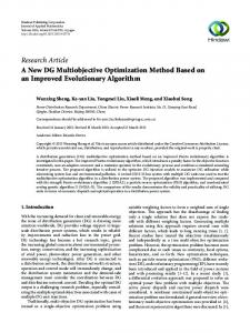
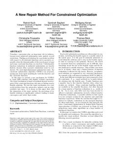
Fig. 8 Best fitness in each iteration for different initial population size. The size of initial population is an important factor that affects the evolution rate and precision. For the purpose of verifying the convergence, three different schemes with the initial population size μ set to 100, 200 and 300 are carried out. Set mutation probability p m=0.1%, and offspring number λ=1.5μ. The best fitness of the three schemes is illustrated in Fig. 8, which shows that as the initial population size increasing, the optimum solution is a little better. The best fitness of the scheme with μ=300 is only 0.07% better than the one with μ=100. It proves that the optimum solution is similar for different initial population size within a reasonable range, which means the optimization method has good convergence. Figs. 9 and 10 are the figure of shape parameters P and section area parameters S of the best individual in each iteration step for the scheme of μ=300. P5 and P6 are angular parameters, and their data is scaled by 0.1 for readability of the whole drawing. Both P and S of the best individual fluctuates seriously as the iteration arising in the first 500 iteration step, and all parameters tend to be stable after 3000 iteration steps.
Fig. 9 The best shape parameter in each iteration.
Fig. 10 The best section area parameters in each iteration.
Table 2 The parameters before and after optimization for the 5000 DWT product oil tanker. Variable
P1
P2
P3
P4
P5
P6
P7
S1
S2
S3
S4
S5
S6
S7
Initial
5.40 0.66 3.00
10.78
50.3 56.2 0.35
185.7
210.0
230.2
230.2
210.2
160.0
112.3
Optimum
5.09 0.52 2.64
11.19
52.6 56.2 0.38
196.2
217.1
232.4
232.4
221.1
171.7
115.8
- 10.1515/ijnaoe-2015-0011 Downloaded from PubFactory at 08/10/2016 01:28:20AM via free access
Int. J. Nav. Archit. Ocean Eng. (2015) 7:142~156
13
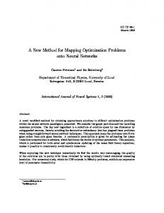
Fig. 11 ISP before and after optimization for the 5000 DWT product oil tanker. Set each parameters of ISP sketch according to the optimum solutions, and the optimized ISP is shown in Fig. 11 compared with the initial one. Before optimization, the total COT volume is 60484 m3, and the one of the optimized scheme is 61706 m 3. With PISOM, COT volume of this tanker is increased by 2.0% under the condition of that all the main design requirements are satisfied. ISP optimization of a 175000 DWT bulk carrier with PISOM In this section, PISOM is applied to a 175000 DWT bulk carrier, the principal dimensions and general arrangement of which is shown in Table 3 and Fig. 12 respectively. The ISP sketch of the bulk carrier is created and shown in Fig. 13. 7 shape parameters and 6 section area parameters are chosen as optimization variables. The setting of the optimization model is similar to the application of the oil tanker in section 5.1 of this paper. Table 3 Principal dimensions of the 175000 DWT bulk carrier. Length pp, m
Breadth, m
Depth, m
Scantling draft, m
Displacement, t
Deadweight, t
278.2
45
25.42
18.2
198645
175000
Fig. 12 General arrangement drawing of the 175000 DWT bulk carrier.
Profile view
Tranverse view
Fig. 13 ISP sketch and optimization variables of the 175000 DWT bulk carrier.
- 10.1515/ijnaoe-2015-0011 Downloaded from PubFactory at 08/10/2016 01:28:20AM via free access
14
Int. J. Nav. Archit. Ocean Eng. (2015) 7:142~156
Figs. 14 and 15 are the figure of shape parameters P and section area parameters S of the best individual in each iteration step. The optimization solution converged after 6510 iteration steps.
Fig. 14 The best shape parameter in each iteration. Fig. 15 The best section area parameters in each iteration. The optimized ISP as well the initial one of the bulk carrier is shown in Fig. 16. Before optimization, the total CH volume is 192900 m 3, and the one after optimization is 196636 m 3. With PISOM, CH volume is increased by 1.94% under the condition of that all the main design requirements are satisfied.
Fig. 16 ISP before and after optimization for the 175000 DWT bulk carrier. From the above two applications, it can come to a conclusion that PISOM is effective in improving the economy of these transport ships. Meanwhile, increasing COT volume also means decreasing WBT volume, which will greatly reduce the cost of ballast water management.
CONCLUSION Dimension-driven and fully-associative are the most important advantage of parametric ISP model. Dimension-driven ensures good changeability of the ISP model, and it is the foundation of PISOM. Fully-associative means all the dimensions of the tank could be optimized theoretically, which greatly extend the application range of PISOM. The section areas of ISP are made dimension constraints and are taken as optimization variables. That makes PISOM more efficient, for the primary performances are mostly related to section area of ISP directly. The algorithm of creating parametric ISP model based on geometric constraint solving proposes in this paper is a general approach, and it is available for most of the conventional ships. As PISOM is independent of ship type as long as parametric ISP model is created, PISOM is a universal optimum design method for most of the transport ships. According to the optimization purpose, different objective could be used in PISOM, such as minimum SWBM, minimum light weight of the hull etc. In a word, PISOM is a useful method for ship general design, and it might be an effective way to improve the economy and safety of most of the transport ship.
- 10.1515/ijnaoe-2015-0011 Downloaded from PubFactory at 08/10/2016 01:28:20AM via free access
Int. J. Nav. Archit. Ocean Eng. (2015) 7:142~156
15
ACKNOWLEDGEMENT This work was supported by the National Natural Science Foundation of China (Grant No. 51409042).
REFERENCE Bhansali, S., Kramer, G.A. and Hoar, T.J., 1996. A principled approach towards symbolic geometric constraint Satisfaction, Journal of artificial Intelligence Research, 4, pp.419-443. Chen, J., Lin, Y., Huo, J., Zhang, M. and Ji, Z., 2010a. Optimal ballast water exchange sequence design using symmetrical multi tank strategy. Journal of Marine Science and Technology, 15(3), pp.280-293. Chen, J., Lin, Y., Huo, J., Zhang, M. and Ji, Z., 2010b. Optimization of ship’s subdivision arrangement for offshore sequential ballast water exchange using a non-dominated sorting genetic algorithm. Ocean Engineering, 37(11-12), pp.978-988. Fudos, I. and Hoffmann, C.M., 1997. A graph-constructive approach to solving systems of geometric constraint. ACM Transactions on Graphics, 16(2), pp.179-216. George, S., Dimitris, K. and Dracos, V., 2008. Sensitivity analysis of the probabilistic damage stability regulations for RoPax vessels. Journal of Marine Science and Technology, 13(2), pp.164-177. International Association of Classification Societies Ltd (IACS), 2006a. Common structural rules for double hull oil tankers (JTP), Section 8.1. London: IMO publisher. International Association of Classification Societies Ltd (IACS), 2006. Common structural rules for bulk carriers (JBP), Chapter 5, Section 1. London: IMO publisher. International Maritime Organization (IMO), 2002. International Convention for the Prevention of Pollution from Ships (MARPOL 73/78). London: IMO publisher. International Maritime Organization (IMO), 2004. International convention for the safety of life at sea (SOLAS) II-1/3-6. London: IMO publisher. Ivanov, L.D. and Wang, G., 2007. An approximate analytical method for calculation of the still water bending moments, shear forces and the ship's trim in the early design stages. Transactions of the Royal Institution of Naval Architects Part A: International Journal of Maritime Engineering, 149(3), pp.1-39. Light, R. and Gossard, D., 1982. Modification of geometric models through variational geometry. Computer Aided Design, 14(4), pp.209-213. Ölçer, A.İ., Tuzcu, C. and Turan, O., 2006. An integrated multi-objective optimization and fuzzy multi-attributive group decision-making technique for subdivision arrangement of Ro-Ro vessels. Applied Soft Computing, 6, pp.221-243. Yu, Y.Y., Chen, M., Lin, Y. and Ji, Z.S., 2010. A new method for platform design based on parametric technology. Ocean Engineering, 37(5-6), pp.473-482. Yu, Y.Y. and Lin, Y., 2013. Optimization of ship inner shell to improve the safety of seagoing transport ship. International Journal of Naval Architecture and Ocean Engineering, 5(3), pp.454-467. Yu, Y.Y., Lin, Y. and Ji, Z.S., 2009. New method for ship finite element method preprocessing based on 3D parametric technique. Journal of Marine Science & Technology, 3(14), pp.398-407. Verroust, A., Schonek, F. and Roller, D., 1992. Rule-oriented method for parameterized computer-aided design. Computeraided Design, 24(10), pp.531-540.
- 10.1515/ijnaoe-2015-0011 Downloaded from PubFactory at 08/10/2016 01:28:20AM via free access