A new microcontroller-based system to optimize the digital conversion of signals originating from load cells built-in into pedals Antonino Proto, Daniele Bibbo, Silvia Conforto, Maurizio Schmid BioLab³, Biomedical Engineering Laboratory Department of Engineering, RomaTre University Rome 00146, Italy Email:
[email protected] Abstract—During cycling, the measurement of forces exerted on the pedal is used to monitor the level of training and to maximize the efficiency of pedaling. In rehabilitation, the force measurement can be used to monitor the functional recovery of a patient during a therapy. In these situations, it is useful to quantify with high resolution these variables. In this work a solution to remove the DC offset at the input of an AD converter for force measurement systems, based on strain gauges load cells, is presented. This circuit has been integrated into a device used in sports and in rehabilitation contexts, that relies on a couple of cycling instrumented pedals. The system designed in this work aims at obtaining these results in a simple way and with its complete integration into the control circuit of the instrumented pedals. Keywords—strain gauge; DC offset removal; automatized calibration; data acquisition.
I.
INTRODUCTION
The use of load cells based on strain gauges technology is usually associated with a Wheatstone bridge circuit (WBC), that permits, with a very simple voltage measurement, the evaluation of the applied forces [1,2]. The voltage variation of the WBC output [3] is due to a resistance variation of each strain gauge caused by its mechanical deformation. In many applications that are designed for an “on the field” purpose, the source of power for the circuit is based on lithium-cells, whose characteristics in terms of voltage levels are generally fixed. Moreover, in a WBC with strain gauge technology, compensation is usually needed to adjust the zero level of the output that can be different from the voltage level expected while the load cell is uncharged. To perform this, a compensation resistor is usually inserted, that is manually regulated to obtain a zero output from the bridge. The output of the WBC requires, in most cases, an amplification of the signal, that in case of a non-zero output provides an offset increase. As a result, signal variations can be non-optimized for the AD converter (ADC), thus limiting its dynamics. So the importance of offset removal is strictly connected with the possibility of having a good digitized signal. In this work a solution to remove the WBC offset at the input of an ADC for force measurement systems designed for cycling application, based on strain gauges load cells, is presented.
978-1-4799-2346-5/14/$31.00 ©2014 IEEE
The measurement system relies on a couple of instrumented pedals that can provide the measure of the force applied by the athlete during cycling [4,5]. This can be used in different application fields, from the sport context to the rehabilitation [6-10]. To this purpose, the designed circuit amplifies the signal by an instrumentation amplifier, then filters, and finally sets an analog DC offset removal circuitry by a microcontroller. It is a new configuration of data acquisition electronic of the instrumented pedals [4,5]. The previous solution used a combination of one Instrumentation Amplifier (In-Amp) and one Programmable Gain Amplifier (PGA) to amplify the signal and to remove the offset. Through a serial communication between calculator and microcontroller, the offset was removed by setting the parameters from the PC. This solution had three problems: (1) using a high gain on InAmp, PGA doesn’t ensure a complete DC offset removal, (2) using a balanced gain between In-Amp and PGA, the amplification of PGA stage produces a SNR deterioration, (3) the In-Amp used isn’t a rail-to-rail amplifier [11]. The new circuit proposed in this work provides a solution to the PGA problem using an In-Amp rail-to-rail I/O to amplify the signal, and the offset is shifted through a linear voltage regulator. Moreover, this method provides an automatic solution to set the parameters during the calibration test. Therefore the aims of the proposed circuit are: (1) to eliminate problems associated with the use of PGA, and (2) to present a revision for an accurate system of automatic calibration, to be used in a variety of applications requiring force measurements [12]. II.
MATERIALS AND METHODS
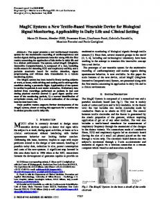
A. Basic concepts and circuit scheme The circuit designed and described in this paper is integrated into each instrumented pedal. It is designed to measure 3 force components Fx, Fy, Fz. The measure of these components is necessary in order to reconstruct the total force applied by the cyclist to the pedal, as showed in Fig. 1.
This circuit provides an automatic calibration, by the microcontroller, to set the correct zero when the system is switched on.
Fig. 1: illustration of the three force components Fx, Fy and Fz.
To obtain the force data from the instrumented pedals, a calibration procedure is needed [5]. It consists in applying known forces along the three axes; this procedure allows to associate, for each channel (Fx, Fy, Fz), the voltage output variation ∆V with the applied force F, obtaining a coefficient C for each channel that satisfies the following equation: F
C ∆V
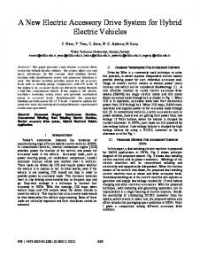
Moreover, it is necessary to set the correct zero of each force channel, in order to optimize the voltage range while pedaling according to the ADC input range and limits. In Fig. 2, the conceptual scheme of the implemented circuit is presented. The analog signal obtained at the output of the Wheatstone bridge is related to strain gauges features, assembled on the load cell with a full-bridge configuration. The voltage signal is amplified using a high precision rail-torail I/O instrumentation amplifier, then it is filtered by an 8th order low-pass Bessel switched capacitor filter, and finally it is AD converted by an high performance microcontroller (µC). Moreover, the µC is used to set resistance values of digital potentiometers. These are necessary to provide an appropriate resistor value to voltage regulators that give the correct reference voltage used to remove the undesired DC offset.
B. Voltage supply The circuit is powered by a single voltage power supply. A 3.7 V lithium cell battery provides the power to the circuit, and a low dropout regulator with reverse current protection (TPS73130 by Texas Instruments) fixed the voltage at 3 V. This voltage supply value is transferred to the integrated components of the circuit. C. Conditioning signal An In-Amp (INA326 by Texas Instruments) for each force channel is used to amplify small signals obtained from WBCs. This kind of amplifier was chosen because it represents a good compromise in terms of precision and cost. This component uses a unique internal circuit topology, which provides rail-torail I/O. It can linearly process inputs up to 20 mV below the negative power supply rail, and 100 mV above the positive power supply rail. It also provides a gain factor up to 10000: this feature is very important for the application described in this work because force components in the chosen application field need to be amplified in the range 1000 - 4000. With these values, in order to obtain a signal with an appropriate CMRR, the chosen amplifier represents a possible solution. As showed in Fig. 2, the signal amplified from the In-amp is then low-pass filtered (MAX7405, Maxim Integrated). This filter draws 2 mA of supply current and allows corner frequencies from 1 Hz to 5 kHz. The cutoff frequency of this filter was set at 30 Hz: this value is compatible with the maximum frequency contained in force signals, considering the typical exercises performed using the instrumented pedals. D. Microcontroller role The microcontroller used in this TM4C123GH6PMI (Texas Instruments).
circuit
is
the
In Fig. 2, the filtered signal is applied to the ADC of the µC. The ADC module provides a 12-bit conversion resolution with unity gain. This microcontroller incorporates the 32-bit ARM Cortex-M4F microprocessor that provides high performances with low power consumption. In order to exploit the whole range of the ADC, the purpose of the system is to provide a value equal to an opportune intermediate value of the ADC input voltage range. This value will be considered as a virtual “zero” of the system and depends on the examined force components: for Fx and Fy, the force application is usually symmetric around zero, so the value is chosen at 1/2 of the range; for Fz, the application of the force is asymmetric, so the value is chosen at 1/3 of the range. For this reason, the µC compares the output value from the ADC module with the virtual “zero”. If the output value is not equal to the correspondent value, the µC sets the necessary value of the voltage regulation-setting resistor, controlling a digital potentiometer. This is used instead of a normal resistor, to control both the positive and negative voltage regulators, with the aim of obtaining a wide range of determined voltage values that are provided to INA326. Fig. 2: block diagram of circuit.
E. Digital potentiometers and linear voltage regulators Digital Potentiometers (DP) used in this circuit are the 50 kΩ, 256 position (8-bit) MCP4451 (Microchip Tech. Inc.) and the 1 kΩ, 256 position (8-bit) AD5254 (Analog Device). These two DPs are connected in series and are used in a coordinated way: the 50 kΩ DP is used for coarse regulation (i.e. steps of 50000 / 256 ≌ 195 Ω), while the 1 kΩ DP is used for fine-tuning (i.e. steps of 1000 / 256 ≌ 3.9 Ω). This second step determines the tolerance that is used to set the virtual “zero”, which is around 0.0002 V. By combining these two regulations, an equivalent 16-bit potentiometer is obtained. It is used to set the appropriate resistance value on linear voltage regulators. Two Linear Voltage Regulators (LVR) for each force component are used: (1) the LT3081 for the negative DC offset, (2) the LT3090 for the positive DC offset. Both regulators (Linear Technology) are precision 50 µA reference current sources that allow a single resistor to program output voltage to any level between 0 V and -32 V for LT3090, and between 0 V and 34.5 V for LT3081, respectively. These two regulators aren’t used together: when a positive or negative voltage signal is required, the correspondent LVR is connected to the INA326 Vref pin, using a logic boolean port controlled by the µC. While the LT3081 is directly powered by the circuit supply, the LT3090 requires a negative voltage that is obtained by an inverting DC-DC converter (TPS63700, Texas Instruments). III.
TESTS & MEASUREMENTS
A. Manual simulation The circuit has been tested manually, by setting the Rset value of the LVR for each force component. Initially, the difference [(Vin+) - (Vin-)] at the output of each load cell was measured, and the sensitivity of the strain gauges was estimated to set the gain resistance Rgain of INA326. Boundary conditions were determined considering that a cyclist is able to impose on the pedal a maximum force equal to: •
± 1000 N for the Fx component;
•
± 200 N for the Fy component;
•
1500 N in the positive direction of the Fz component and -500 N in the negative direction.
In order to evaluate the necessary gain for each channel, the value of sensitivity (µV/N) with unitary gain - obtained measuring the output of each WBC while a load test was applied - was multiplied by the max value of force to be applied, obtaining the maximum voltage level without amplification. Then, by dividing the half of voltage range of the AD converter (e.g. 3 V / 2 = 1.5 V) for this value, the necessary gain to optimize the dynamic of conversion was obtained. Once the voltage values on the output of INA326s were measured, the DC offset values to be removed were calculated
and the Rset of linear voltage regulators was manually adjusted to provide the correct voltage value on the input of the ADC module. In Table I, the results of the manual simulation are available: TABLE I.
is:
SIMULATION RESULTS Results
Force component
Sensitivity
Gain amplifier
R2 of INA326
Fx
0.82 ± 0.01 µV/N
1839 V/V
1.84MΩ
Fy
2.24 ± 0.01 µV/N
3330 V/V
3.33MΩ
Fz
1.33 ± 0.01 µV/N
1132 V/V
1.13MΩ
The equation to calculate the Vout at the output of INA326 V
F
INA
VF
_
VF
_
GF
V
F
INA
VF
_
VF
_
GF
V
F
INA
VF
_
VF
_
GF
With the differences measured for each component, the following values were thus used: Vout-Fx-INA326 = 2.052 V; Vout-Fy-INA326 = 0.495 V; V out-Fz-INA326 = 1.311 V. To get a calibrated system, the linear voltage regulators will add or subtract the voltage value in order to obtain the virtual “zero” of the system. To add voltage the LT3081 is used, while to subtract voltage the LT3090 is used. The equation to set the Rset of voltage regulator is: V
R
F
R
F
R
F
LT
_F
I V
LT
_F
I V
LT
_F
I
With the differences measured for each component, the following values were thus used: Rset-Fx = 11.032 kΩ; Rset-Fy = 20.100 kΩ; Rset-Fz = 3.784 kΩ. These values are thus used to calibrate the system for the specific tested application. With this calibration, the system is able to record force data with an optimized range. B. Comparison tests The circuit proposed in this work has been compared with a previous solution that used INA125s (Texas Instruments) plus PGA308s (Texas Instruments) to amplify the signal and to remove the offset. The force measurements were performed on the Fz component, with no load applied, and with 5, 10 and 15 kg, corresponding to around 50, 100, and 150 N. After measuring forces with the original configuration, the gain of the INA326 was calculated to reproduce the same voltage variation measured with the INA125 plus the PGA308 components.
In Table II, the Rgain and the voltage variations obtained when the load is applied, are shown. TABLE II. Load 5kg 10kg 15kg
RESULTS OF THE TWO CONFIGURATIONS Results Rgain
INA125 = 100 Ω ; INA326 = 1718 Ω. INA125 = 100 Ω ; INA326 = 1718 Ω. INA125 = 100 Ω ; INA326 = 1718 Ω.
∆VXkg INA+PGA
∆VXkg INA326
0.099 ± 0.006 V
0.099 ± 0.003 V
0.195 ± 0.006 V
0.198 ± 0.003 V
0.289 ± 0.006 V
0.290 ± 0.003 V
Table II shows that results obtained with the two different configurations are similar in terms of overall sensitivity, with the added value of the second configuration being less noisy (lower standard deviation), and with a single amplification stage. IV.
CONCLUSION
The solution proposed in this work is a new configuration of the conditioning stage of two instrumented pedals used in sports and in rehabilitation context. This circuit simplifies the amplification stage and the offset removal stage, and in this paper a theoretical study to automatize the system is also outlined. In comparison with the previous configuration, where the amplification and the offset removal were obtained by a In-Amp plus a PGA, with the proposed configuration, it was possible to minimize problems associated with the following: (1) using an high gain on In-Amp, the PGA did not totally remove offset, (2) using a balanced gain between In-Amp and PGA, the amplification of PGA stage produces a SNR deterioration. Furthermore, to calibrate the system, the PGA was set by a computer. With this new configuration, the circuit has a single amplification stage. The DC offset removal is implemented through a linear voltage regulator that eliminates offset values very close to zero even with high gain values. Moreover, the new configuration makes the calibration phase of the measurement system automatic, thanks to the use of digital potentiometers controlled by the microcontroller.
This solution simplifies the use for experimenters, without the necessity to have the designers present when the instrumented pedals are used. Furthermore, this circuit is also implementable in other force measurement systems, such as force platforms, instrumented fitness devices, and other. REFERENCES [1]
B. Maundy, S.J.G.Gift, “Strain gauge amplifier circuits,”IEEE Transl. Instrumentation and Measurements, vol. 62, pp. 693-700, April 2013. [2] S. Tanner, S. Ali, M. Banjevic, A. Arami, K. Aminian et al., “An analog front-end and ADC integrated circuit for impiantable force and orientation measurements in joint prosthesis,”Wireless Mobile Communication and Healthcare, vol. 61, pp. 295-302, November 2012. [3] T.T. Nguyen, L.A.L. Fernandes, P. Häfliger, “An energy-efficient implantable transponder for biomedical piezo-resistance pressure sensors,” IEEE Sensors Journal, vol. 14, pp. 1836-1843, June 2014. [4] D. Bibbo, S. Conforto, I. Bernabucci, M. Schmid, T. D’Alessio, “A wireless integrated system to evaluate efficiency indexes in real time during cycling,” IFMBE Proceedings, vol. 22, pp. 89-92, November 2008. [5] S. Conforto, S.A. Sciuto, D. Bibbo, A. Scorza, “Calibration of a measurement system for the evaluation of efficiency indexes in bicycle training,” IFMBE Proceedings, vol. 22, pp. 106-109, November 2008. [6] C. De Marchis, M. Schmid, D. Bibbo, A.M. Castronovo, T. D’alessio et al., “Feedback of mechanical effectiveness induces adaptions in motor modules during cycling,” Frontiers in Computational Neuroscience, vol. 7, art. 35, April 2013. [7] C.D. Lazzari, A. Balbinot, “Wireless crankarm dynamometer for cycling,” Sensors and Transducers, vol. 128, pp. 39-54, May 2011. [8] D. Bibbo, S. Conforto, C. Gallozzi, T. D’Alessio, “Combining electrical and mechanical data to evaluate muscolar activities during cycling,”WSEAS Trans. Biology and Biomedicine, vol. 3, pp. 339-346, May 2006. [9] M. Castronovo, S. Conforto, M. Schmid, D. Bibbo, T. D’Alessio, “How to assess performance in cycling: the multivariate nature of influencing factors and related indicators,” Frontiers in Physiology, vol. 4, art. 116, May 2013. [10] D. Bibbo, S. Conforto, I. Bernabucci, M. Carli, M. Schmid et al., “Analysis of different image-based biofeedback models for improving cycling performances,” Proceedings of SPIE, vol. 8295, February 2012. [11] K.A. Ng, P.K. Chan, “A CMOS analog front-end IC for portable EEG/ECG monitoring applications,” IEEE Trans. on Circuits and Systems I, vol. 52, pp. 2335-2347, November 2005. [12] P. Cappa, S. Silvestri, S.A. Sciuto, “On the robust utilization of nonparametric tests for evaluation of combined cyclical and monotonic drift,” Measurement Science and Technology, vol. 12, pp. 1439-1444, September 2001.