A New System for Computer–Aided Intraoperative Simulation and Postoperative Facial Appearance Prediction of Orthognathic Surgery Yan-Ning Zhang #1, Pei-Fang Zhai #2, Jian-Yu Shi #3, Jiang-Bin Zheng #4, Hong Zhou*5, Jiang-Bo Li*6 #
School of Computer Science, Northwestern Polytechnical University P.O. BOX 756, Xi'an Shaanxi, 710072, P.R China 1
[email protected]
*
Xi'an JiaoTong Univ. Stomatology Hospital No.98 XiWu Road, Xi'an Shaanxi, 710003, P.R China Abstract—This paper presents a new system for computeraided orthognathic surgery which aims at correcting dento-facial defects and keeping patient away from much radiation and high cost of CT or MRI imaging. The system allows simulating the surgical correction on virtual 3-D model of the skull reconstructed with the acquisition of radiographs of three orthogonal views and facial mesh data generated by 3-D laser scanner and the use of build-in skull template mesh. Surgery simulation includes maxilla Le Fort I and mandible bilateral SSRO osteotomies by interactive cutting of jaw bone. With the help of a special registration procedure, we are able to align the reconstructed skull model and a facial skin model. Upon fulfilment of the registration and virtual osteotomies, the system provides further assistance with predicting postoperative appearance of patient. Finally, we apply the system on one patient in clinical practice and achieve satisfied result.
I. INTRODUCTION Flaws of the dento-facial bone can result from an inborn abnormity, a growing problem, or even a traumatic incident and have serious result for the affected individual: difficulties in chewing, pain and even worse situation. Orthognathic surgery is just the way to restore such defects. Typically, preoperative plan is set down by experienced surgeon who simulates surgery and predicts the postoperative appearance according to 2D cephalometry based on radiographs (X-ray films) [1], [2]. But osteotomy often requires displacement and relocation with six degrees of freedom in 3-D space. Radiographs are only projections of the anatomy and lack depth information so that they are not able to meet the demand of orthognathic surgery. For this reason, CT and MRI technologies are developed to assist orthognathic surgery and have achieved a lot in the past ten years due to their ability of acquiring abundant and accurate data [3-9]. However, many patients are unwilling to expose themselves to much radiation of CT or MRI and burden high cost of imaging. Moreover, those systems base on CT or MRI intrinsically require the high processing performance of the resulting large quantity of 3-D voxel data [6],[9]. So it is consequently hard to perform in real time on normal PC. These factors are still obstructive to widen the use of computer in clinical practice.
978-1-4244-2295-1/08/$25.00 © 2008 IEEE
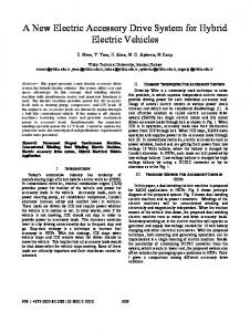
In this paper we present a new system for orthognathic surgery which addresses two issues: computer–aided intraoperative simulation and postoperative facial appearance prediction. The proposed system provides totally the advantages of little radiation to patient, 3-D visualization of orthognathic surgery and predicting of postoperative visage of patient and has been applied in a real osteotomy case. II. ARCHITECTURE OF OUR SYSTEM The system consists of the following modules: data acquisition, reconstruction of skull, registration of facial skin and skull, virtual osteotomy, and facial appearance prediction. The architecture of our system is represented in Fig. 1 and is detailed in the following sections.
Data Acquisition Reconstruction of Skull
• Radiographs • Facial Mesh Model • Matching Build-in Template Skull • Selecting Key Vertices • Deformation
Registration of Facial Skin and Skull
• Layout of Registration Vertices • Registration Procedure
Virtual Osteotomy
• Interactively Cutting Jaw Bone • Simulating Osteotomy
Facial Appearance Prediction
• Calculating Postoperative Displacement • Deformation and Textured Mapping
Fig. 1. The architecture of our system
A. Data acquisition To a specific patient, we need to acquire his/her 3D face mesh data (soft tissue) and radiographs of his/her head (hard tissue). Soft tissue data can be achieved by 3D laser scanner which is completely harmless to patient and makes accurate face mesh data, while hard tissue data can be obtained by normal X-ray camera which is cheap and used broadly in the world.
137
MMSP 2008
Three radiographs (X-ray films) can be shot from frontal, lateral and bottom views of patient head respectively. This way gives us a good advantage that these three radiographs are mutual-orthogonal projection planes. As a result, the 3-D coordinates of any vertex of hard tissue can be exclusively determined by its orthogonal projection points in these three films. A standard template skull pre-built in our system is cooperated with radiographs to reconstruct the patient's skull which are further aligned with patient's face mesh to predict postoperative facial appearance. B. Reconstruction of Skull Because of the natural complexity of skull shape, it is very difficult to find projected points for every vertex of skull in 2D radiographs which have the inherent non-legibility and lack depth information. In other words, it is impossible to reconstruct the whole skull model from only three X-ray films although they are orthogonal mutually. However, we can always reconstruct a few key vertices of skull which can be categorized into three groups: match, shape and surgery. The first group is used to match the patient's skull and the build-in template skull. The second group is contributing to reconstruct the rough shape of skull. The last group is assisted to reconstruct the detailed skull region which is depended on surgery content. The whole reconstruction of skull includes three stage described as follows: Stage 1: to match the size of build-in template skull to the one of patient. Due to the different size of template and patient's skull, we firstly scale template skull to the close size of patient's skull with four match vertices. For this purpose, we adopt four vertices in ear-eye plane [10] which is a horizontal plane of cephalometry and anatomy. Fig. 2 shows the layout of these match vertices which are denoted as L1, L2, L3 and L4 respectively. Then, we define the origin of the 3-D coordinates system as the mean vertices of L1 and L2 for both radiographs and template skull mesh respectively. L1 and L3 are now symmetric to L2 and L4 respectively according to ZOY plane of coordinates system. And the ear-eye plane is taken as XOZ plane. Last, both radiographs and built-in template skull mesh are move linearly to the coordinates system as shown in Fig. 2. The linear scaling of built-in template skull is further implemented by aligning its L1 and L2 vertices with those ones of radiographs. Now, the match between template skull and radiographs is done. Stage 2: to select key vertices in both matched skull mesh and radiographs with interactive way. With mouse, we perform interactive selection of key vertices in skull mesh and in frontal and lateral views of radiographs respectively. Because radiographs are indeed projections of the anatomy and lack depth information, the bottom view of radiographs is used to validate some key vertices whose projected points are covered by others in front or lateral views. Upon such interactive selection, we now obtain the key vertices of both template skull mesh and radiographs in the same 3-D coordinates system. The key vertices of template skull mesh are referred to as beginning
vertices while those of radiographs are called destination vertices which are the actual key vertices of patient's skull. Fig. 3 shows the layout of both beginning and destination vertices in template skull mesh and radiographs respectively. The total number of beginning or destination vertices is 54 in our surgical case.
(a) Match vertices on mesh with vertex (b) Match vertices on mesh with facet mode mode
138
(c) Match vertices on frontal view of radiograph
(d) Match vertices on lateral view of radiograph
Fig. 2. The layout of match vertices in both template mesh and radiographs
(a) Frontal view of radiograph
(b) Lateral view of radiograph
(c) Bottom view of radiographs
(d) Built-in Template Skull
Fig. 3. The layout of key vertices of both skull mesh and radiographs
Stage 3: to reconstruct patient's skull with deformation. Finally, beginning and destination vertices are used to reconstruct patient's skull by deforming the calibrated template skull with the help of RBF deformation algorithm [11]. After RBF deformation, new coordinates of all vertices of template skull mesh can be calculated so that the patient's skull mesh is reconstructed.
We calculate and pick up in turn the coordinates of these registration vertices from both radiographs and face mesh. The registration can be done by aligning them one by one in the same coordinates system with linear mapping, for example, scale, rotation and translation. Upon the registration, next virtual osteotomy will be operated and further patient appearance will be achieved in succession.
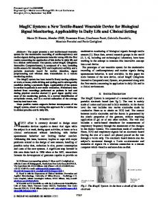
C. Registration of facial skin and skull In order to fulfill the coming registration of soft and hard tissue data, pre-calibration should be performed by five lead pellets which are stuck on patient's face and will not make patient uncomfortable due to their small size and few count. Because the patient's expression and speaking motion always change the relative position of kinetic face region, these lead pellets are arranged on non-kinetic face region and their layout is shown in Fig. 4.
D. Virtual Osteotomy Osteotomy is one of the most important technologies of jaw surgery. Surgeons often depend on their experience to perform this kind of surgery. Computer-assisted virtual osteotomy can be just a navigator for surgeon, especially a rookie who will perform orthognathic surgery. Because the way of segment of jaw bone are decided by surgical contents, the virtual osteotomy is an interactive operation which involves the technology of mesh segmentation. Here our system uses an interactive cuboid cutting algorithm to simulate two types of osteotomies: LeFort I and sagittal split ramus osteotomies (SSRO). Fig. 5 shows the results of these two osteotomies.
1
1 4
2 3
5
2
5
3
(a) Portraits
(a) The result of Le Fort I
(b) The result of SSRO
Fig. 5. Virtual Osteotomies Result (b) Radiographs
During osteotomies, each free part of jaw bone is just interactively manipulated to the pre-planned locations of surgery with linear ways in three dimensions, including translation and rotation.
(c) Facial Mesh Fig. 4. The layout of five lead pellets of patient
As shown in Fig. 4, pellets 1, 2, 3 are arranged in verticalcross plane of patient's head, while pellets 4, 2, 5 are arranged in its horizontal-cross plane. These lead pellets can be clearly imaged as highlighted white points in all radiographs of patient and also be identified easily as small tubers in his/her face mesh data acquired by 3-D laser scanner. With picking out the coordinates of white points in radiographs and small tubers in mesh respective, we are able to align radiographs and mesh in the same system of coordinates. These points are known as registration vertices of face mesh and reconstructed skull in presented system.
E. Facial appearance prediction To predict the postoperative facial appearance is a difficult task because of complex anatomical structure linking between bone, jaw and muscle. Some attempts and approaches have been presented [12],[8],[13],[9]. Here, we propose an approach based on Chinese public statistical dataset of soft and hard tissues displacement ratios of orthognathic surgery [14],[15]. Firstly, some concerned items of displacement ratios are queried from this dataset with respect to the style of surgery. Next, the postoperative displacement of face skin is calculated by its preoperative displacement and the preoperative and postoperative displacements of jaw bone. Then, RBF deformation algorithm [11] is once more applied on facial mesh to get the prediction of postoperative facial appearance. Last, the photo of patient is further mapped on the predicted facial mesh to show the textured visage.
139
III. RESULTS AND DISCUSSION One of the purposes of our system is to guide surgeon to make preoperative planning and could even be a navigator of real orthognathic surgery by virtually simulating restoration of proper dental occlusion. Another inspiring goal is the prediction of postoperative facial appearance of patient. Now, our system for computer-assisted orthognathic surgery has been used in clinical practice for maxilla Le Fort I osteotomy and mandible bilateral SSRO. Firstly, we give the result of skull reconstruction and make a comparison of radiographs and reconstructed skull mesh, especially their lateral views, reconstructed skull mesh can show the feature of patient's skull well, especially incorrect jaw bone. As shown in Fig. 6, our system is capable to rightly reflect the dento-facial defects of patient with the further benefit of little radiation and less payment to patient. Furthermore, the system is also able to produce a more accurate model by using more key vertices during interactive selection stage of key vertices. But the increasement of the number of key vertices will also increase the interactive selection and computation time. This is usually up to both surgeon and patient.
(a) Lateral view of radiographs
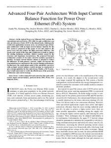
Finally, two types of osteotomies Le Fort I and SSRO are all performed together on the selected patient. During Le Fort I osteotomy, the back section of wedge-shaped jaw bone is lifted up with 3mm and its front section is declined with 1mm. During SSRO, free bone of mandible is moved back with 7mm. Fig. 8. shows the comparison of preoperative and postoperative skull, face and textured visage of patient. The results of preoperative and postoperative visages of patient represent that the correction of his/her defects of dento-faical bone is acceptable.
(a) Preoperative Skull Mesh Model
(b) Postoperative Skull Mesh Model with two osteotomies
(c) Preoperative facial skin model
(d) Postoperative facial skin model
(e) Preoperative Lateral View
(f) Predicted Postoperative Lateral View
(b) Reconstructed Skull
Fig. 6. The result of reconstruction
Secondly, we show the registration of skull and face mesh data in Fig. 7. It is worth noting that the back region of skull is odd and abnormal by the fact of few shape and surgery vertices are set in that region where RBF deformation algorithm can not achieve good result. Fortunately, such region is not concerned and involved in both osteotomies and prediction of facial appearance. In other words, such scenario does not shadow the functionality of our presented system.
Fig. 8. The comparison of preoperative and postoperative models
As above described, in a nutshell, our system does depict and visualize the intraoperative simulation and postoperative facial appearance rightly and can be further a navigator of orthognathic surgery.
(a) Frontal view
(b) Lateral view
Fig. 7. The registration of facial skin and skull
IV. CONCLUSION This paper proposed a new system for computer–aided intraoperative simulation and postoperative appearance prediction of orthognathic surgery with the acquisition of radiographs of three orthogonal views and facial mesh data generated by 3-D laser scanner and the use of build-in skull template mesh. This presented system allows orthognathic
140
surgery to be performed on little-radiation and low-cost platforms in real time and eliminates the high processing requirement of the large quantity of resulting 3-D voxel data generated by CT or MRI imaging. More importantly, both surgeon and patient can be allowed to preview the whole procedure of the coming osteotomies and the patient's predicted facial appearance. As a result, the former can use the system as a guideline of orthognathic surgery and operate surgery with lower risk. Meanwhile, the mentality of the latter will transfer from misgiving to recognition and to acceptance of orthognathic surgery in terms of psychology. Furthermore, the system can enhance the surgeon-patient communication which will help surgeon make more reasonable and patientspecific preoperative planning. In the future, more types of osteotomies will be simulated in our system and clinical practice will be tracked continuously to further exploit, validate and improve the system. ACKNOWLEDGMENT This paper is supported by National Natural Science Foundation of China (No. 60472072), Science and Technology Planning Project of Shaanxi Province of China (No. 2004K05-G23) and in part supported by Program for New Century Excellent Talents in University (No. NCET-0508661), China Postdoctoral Science Foundation (No. 20070421130) and the Foundation of National High Technology Research and Development Program of China (863 Program) ( No. 2006AA01Z324). REFERENCES [1] Taylor, R.H., et al., An image-directed robotic system for precise orthopaedic surgery. Robotics and Automation, IEEE Transactions on, 1994. 10(3): p. 261-275.
[2] Jiong, X., et al. Computer Aided Simulation System for Orthognathic Surgery. in Computer-Based Medical Systems, 1995., Proceedings of the Eighth IEEE Symposium on. 1995. [3] Ip, H.H.S., et al. Simulated patient for orthognathic surgery. in Computer Graphics International, 2000. Proceedings. 2000. [4] Troulis, M.J., et al., Development of a three-dimensional treatment planning system based on computed tomographic data. J. Oral Maxillofac. Surg., 2002. 31: p. 349-357. [5] Xia, J.J., J. Gateno, and J.F. Teichgraeber, Three-dimensional computer-aided surgical simulation for maxillofacial surgery. Atlas Oral Maxillofac. Surg. Clin. North Am, 2004. 13(1): p. 25-39. [6] Lin, Y.-p., et al. Real-time Navigation in Orthognathic Surgery. in Engineering in Medicine and Biology Society, 2005. IEEE-EMBS 2005. 27th Annual International Conference of the. 2005. [7] Cevidanes, L.H., et al., Superimposition of 3D conebeam CT models of orthognathic surgery patients. Dentomaxillofac. Radiol., 2005. 34(6): p. 369-375. [8] Westermark, A., S. Zachow, and B.L. Eppley, Three-dimensional osteotomy planning in maxillofacial surgery including soft tissue prediction. J. Craniofac. Surg, 2005. 16(1): p. 100-104. [9] Chapuis, J., et al., A New System for Computer-Aided Preoperative Planning and Intraoperative Navigation During Corrective Jaw Surgery. Information Technology in Biomedicine, IEEE Transactions on, 2007. 11(3): p. 274-287. [10] Du Chesne, A., et al., Post-mortem orthopantomography – an aid in screening for identification purposes. International Journal of Legal Medicine, 2000. 113(2): p. 63-69. [11] Boer, A.d., M.S.v.d. Schoot, and H. Bijl, Mesh deformation based on radial basis function interpolation. Comput Struct 85, 2007(11-14): p. 784-795. [12] James, X., et al., Three-dimensional virtual-reality surgical planning and soft-tissue prediction for orthognathic surgery. Information Technology in Biomedicine, IEEE Transactions on, 2001. 5(2): p. 97107. [13] Yi-Je, L., et al. Soft Tissue Deformation and Cutting Simulation for the Multimodal Surgery Training. in Computer-Based Medical Systems, 2006. CBMS 2006. 19th IEEE International Symposium on. 2006. [14] CD, Q. and e. a, The short-term and long term soft-tissue profile changes accompanying mandibular advancement surgery Am J Orthod, 1983. 84(1): p. 29-36. [15] Ying, G., Jaw face individually fictitious rebuild from the outline of three-dimensional epidermis and bone organize the surface and uses in the jaw surgical field of Basic theoretical research,Ph. D. thesis. 2004, Ji Lin University Stomatological Hospital.
141