order calculus, time-domain control, Crone controller ... departure point for checking, in deep, the relative ... Three frequency-domain methods are available.
NINTEGER: A NON-INTEGER CONTROL TOOLBOX FOR MATLAB Duarte Valério1; José Sá da Costa Technical University of Lisbon, Instituto Superior Técnico Department of Mechanical Engineering, GCAR Av. Rovisco Pais, 1049-001 Lisboa, Portugal Phone: +351 21 8417187 Fax +351 21 8498097 Email: {dvalerio;sadacosta}@dem.ist.utl.pt
Abstract: This paper describes a toolbox for MatLab, freely downloadable from the Internet, fit for developing fractional order controllers, both in the time and the frequency domains. It includes about thirty methods for implementing approximations of fractional order operators (most of which in the time domain) and three identification methods. Fractional PID controllers and CRONE controllers (of all the three generations) may be implemented in both domains. The toolbox is built on a set of functions, kept to a minimum and as simple as possible, that may be called from the command prompt; and also includes a user-friendly graphical interface for interactive controller development. Keywords: fractional (non-integer) order control, Matlab toolbox, fractional (non-integer) order calculus, time-domain control, Crone controller
1. INTRODUCTION Ninteger is a toolbox for MatLab intended to help developing fractional (or non-integer) order controllers for single-input, single-output plants, and assess their performance. Its code may be freely distributed and altered (with mild restraints essentially related to acknowledging the source). It was developed because devising controllers that make use of fractional calculus requires running several algorithms which are not found in toolboxes distributed with Matlab or in any easily available toolbox. (There is, for instance, the Crone toolbox (Cois et al., 2002; Oustaloup et al., 2002), developed by the Crone team at Bordeaux, that also deals with multiple-input, multiple-output plants, which is neither free nor easily available.) Many of these algorithms concern building integer order plants that approximate to some extent the behaviour of fractional order ones. Since there are (literally speaking) dozens of alternatives, in both the frequency and discrete time domain, implementing them all in a systematic way is an unavoidable departure point for checking, in deep, the relative merits and demerits of each. Other algorithms 1
concern ways of fitting parameters: those specific to fractional calculus must also be implemented in a systematic way (there is of course no need to implement methods like least-squares optimisation that may also be used for that purpose: Matlab already has nice functions for that). The toolbox is free to encourage academic use of fractional control, and because so it is easier to profit from suggestions and improvements from other users. Its code was kept as simple as possible to encourage code reuse by other users. It comprises most wellknown contributions to this area from other researchers as well as some from the authors’ papers (Valério et al., 2002, 2003a, 2003b, 2004); fractional PIDs are, to the best of our knowledge, being systematically provided in a toolbox for the first time. Sections 2 to 5 of this paper describe the functions that implement approximations of the several types of control. Section 6 describes functions for identifying models. Section 7 describes the toolbox's graphical interface. Some conclusions are drawn in section 8.
Partially supported by programme POCTI, FCT, Ministério da Ciência e Tecnologia, Portugal, grant number SFRH/BD/2875/2000, and ESF through the III Quadro Comunitário de Apoio.
2. APPROXIMATIONS OF FRACTIONAL ORDER DERIVATIVES AND INTEGRALS Several formulas are implemented for obtaining integer-order transfer functions with a behaviour that approximates that of C ( s ) = ks v , v ∈
(1)
None is better than all others over all possible circumstances. Having them all available may help to compare their strong and weak points. Three frequency-domain methods are available (Oustaloup, 1991; Vinagre et al., 2000; and references therein). The first is the Crone method, which uses a recursive distribution of N poles and N zeros: 1 + s ω zn n =1 1 + s ω pn N
C ( s ) = k ′∏
(2)
α = ( ω h ω l ) , η = (ω h ω l )
1− v N
(3)
ω pn = ω z , n −1α , n = 1… N For a negative v the role of zeros and poles is interchanged. The controller is reckoned from k, v, ω l , ω h and N. The second is Carlson's method, that solves C a ( s ) = g ( s ) using Newton's iterative method:
( a − 1) Cna−1 ( s ) + ( a + 1) g ( s ) ( a + 1) Cna−1 ( s ) + ( a − 1) g ( s )
(4)
The fractional order is 1/a (thus restricted to inverses of integers) and function g is set to s. Iterations necessary to reach (or exceed) a specified minimum number of zeros and poles are performed. The result is valid in a range of frequencies centred on 1 rad/s, that may be shifted by multiplying all zeros and poles by a given frequency. The third is Matsuda's method, that recursively approximates a transfer function C, with a gain known at several frequencies ω0, ω 1, ω 2, ω 3, …, as +∞
C ( s ) = d 0 (ω 0 ) ; ( s − ω k −1 ) d k (ω k ) k =1 d 0 (ω ) = C ( jω ) , d k +1 (ω ) =
It should be noticed that the requirements of all functions are as much as possible the same. The number of poles and zeros is namely always used instead of related parameters such as a number of iterations or a number of sampling frequencies. Since fifteen of these methods make use of continued fractions, the toolbox includes a complete set of functions for dealing with such mathematical entities.
Truncated McLaurin series expansions of powers of backwards finite differences v
1 − z −1 , T
3 − 4 z −1 + z −2 2T
v
and
v
ω z1 = ωl η , ω zn = ω p , n −1η , n = 2… N
Cn ( s ) = Cn −1 ( s )
Beyond these frequency domain methods, twentyeight discrete time-domain methods are available. A list of these is found in Table 1; details on how they are obtained and references are found in (Valério et al., 2003b). They are all computed from k, v, the sampling time and the desired number of poles and zeros.
Table 1. List of discrete time-domain formulas.
Gain k' is adjusted so that if k is 1 then |C(s)|=0 dB at 1 rad/s. Zeros and poles are found inside a frequency interval [ω l ; ω h ] and are given, for a positive v, by v N
frequencies. Thus the toolbox requires k, v, the limits of a frequency range and the desired number of zeros and poles (that dictates the number of frequencies ω).
(5) ω − ωk d k (ω ) − d k (ω k )
This method is applied feeding (5) with the gain of (1) reckoned at several logarithmically spaced
11 − 18 z −1 + 9 z −2 − 2 z −3 6T Truncated McLaurin series expansions of powers of Tustin and Simpson formulas v 3 (1 + z −1 )(1 − z −1 ) 2 1 − z −1 and −1 T 1 + 4 z −1 + z −2 T 1+ z FIR filters following theoretical impulse or step responses at sampling times t − v −1 1 t −v L −1 s v = and L −1 s v × = Γ ( −v ) s Γ ( −v + 1) v
Truncated continued fraction expansions of all of the above (seven additional formulas in all) All the above formulas reckoned for an order -v and inverted (fourteen additional formulas in all) 3. FUNCTIONS ENSURING A REAL ORDER BEHAVIOUR FOR THE OPEN-LOOP Two functions are included for devising a controller ensuring an open-loop behaviour similar to G ( s ) C ( s ) = ks v , v ∈
(6)
The frequency-domain one corresponds to the socalled second generation Crone control (Oustaloup, 1991), that stems from an identification method making use of the fact that transfer functions C1 ( s ) = k
∏1 + s ω j
zj
∏1 + s ω pj j
, C2 ( s ) = k
1 (7) + 1 ∏ s ω zpj j
may have the same phase: it suffices that the poles of C2 be the poles of C1 and the complex conjugates of the zeros of C1. So, if we know the phase φi and the gain gi of the plant to identify at N frequencies ωi, we will want the M poles of C2 to verify M
−∑ arctg (ω i ω zpj ) = φi , i = 1… N
(8)
j =1
By solving this system (which may be determinate, underdeterminate or overdeterminate) we obtain the frequencies of the poles of C2, that may correspond to a zero or a pole of C1, possibilities being 2M. Each will be checked in turn, and the one leading to a gain closer to experimental values gi will be chosen.
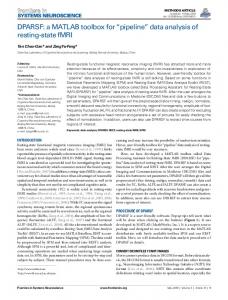
The controller is chosen so that the frequency response of the open-loop avoids, under all conditions, those points of the Nichols plot corresponding to high-closed loop gains or low damping coefficients. These correspond to the zones near the origin, as seen in Fig. 1. Open-loop frequency behaviours are (for the sake of simplicity) usually forced to be linear, corresponding to open-loop functions of one of the forms: s a + jb s a cos ( b log s ) C ( s ) G ( s ) = Re = ω0 ω0 −a s C (s)G (s) = ω 0 cos ( b log s )
To devise a controller, we notice that (6) dictates that the phase of C should complement that of G to obtain a constant result in those N frequencies:
20
M J = ∑ ∑ arctg (ω i ω zpj ) − φi i =1 j =1 N
2
(10)
When used to identify a model, the squares of errors in gain are also taken into account, weighted so that error of 1º in the phase and 1 dB in the gain are equally important. Under no conditions is it ensured that all poles and zeros will be stable. 4. FUNCTIONS ENSURING A COMPLEX ORDER BEHAVIOUR FOR THE OPEN-LOOP Third-generation Crone control is fit for plants that may undergo parameter variations (Oustaloup, 1991).
0 dB
-0,4 dB
-0,8 dB -1 dB
2 dB 10 3 dB gain (dB)
-3 dB
5 5 dB 7 dB 9 dB 0
-5 dB -7 dB
-5
This identification method is implemented and may be used in two ways: inputting ωi, φi, gi and M, a transfer function with M zeros and poles will be returned to model the plant characterised by the first three; inputting ωi, φi and M only, a controller is returned as explained above. In this case φi should be the right-hand member of (9), and the frequency where gain will be 0 dB should be specified.
-9 dB -11 dB
-10 -15
-13 dB -3
-2.5
-2
10
-1.5 -1 phase (rad)
-0.5
0
5 gain (dB)
The second function in this category is the discrete time-domain counterpart of the one above. Unfortunately no relation similar to (7) exists in the z-1 domain for the general case (Valério et al., 2004). Zeros and poles are thus found with the multidimensional non-linear minimisation NelderMead algorithm, as provided in function fminsearch. The function may be used in the same two ways as the previous one, the sampling time being an additional parameter. When used to devise a controller, the penalty function is simply
0,4 dB
15
arg C ( jω i ) = vπ 2 − arg G ( jω i ) , i = 1… N (9) (6) imposes no constrain on gain, and thus once the poles of C2 are obtained they will be considered zeros or poles of C1 according to what makes them stable.
0,8 1 dB dB
(11)
0 ζ =0,1 ζ =0,2 -5 ζ =0,3 ζ =0,4 ζ =0,6
-10
ζ =0,8
-3
ζ =0,5 ζ =0,7
-2.8
-2.6 -2.4 phase (rad)
-2.2
Fig. 1. Closed-loop gain and damping coefficient as function of open-loop gain and phase. The purpose of third generation Crone controllers is shown in the upper plot of Fig. 1: closed-loop gain (straight line) is never larger than a given value, 0 dB in this instance, for the nominal plant; and even in the presence of plant uncertainty (a misplaced zero in this instance) the corrected closed-loop Nichols plot (grey line) hardly goes beyond the 0 dB mark, if at all. The toolbox receives the plant to control, the variations its parameters may undergo, the specification (maximum closed-loop gain or minimum closed-loop damping coefficient), and the frequency range where the specification is to be respected. The frequency behaviour of the controller and the parameters of (11) (which are two different specifications of the same) are returned. The
controller should then be built using one of the functions described above in section 3. 5. FRACTIONAL ORDER PIDs Methods of section 2 are also available for building fractional order PIDs (Podlubny, 1999): C ( s ) = k P + k D s vD + k I s vI
(12)
In most cases this is simply summing up two approximations corresponding to k I s vI and k D s vD with the proportional part. It is not so in two cases. When Matsuda method is used, the gain of the PID is directly used in (5). And if vI and vD are multiple of each other (the smallest being the inverse of an integer) Carlson method may be used setting function g in (4) to k DaD s1+ n + k IaD 1 n , if vD = ∧ vI = − n aD aD s k DaI s1+ n + k IaI n 1 , if vD = ∧ vI = − s aI aI
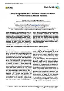
dialogue of the graphical interface. (When called by the first time no fields are filled in and no plot appears.) Using the buttons in its right side other dialogues may be called for devising the four types of controllers described in the previous sections. After reckoning a controller, performance evaluation is shown in the main dialogue. Clicking Non-integer derivative controller in the main dialogue, the dialogue of Fig. 2 appears. It allows choosing the type of approximation and receives the parameters listed in section 2; since not all of them are always necessary, only those that are (depending on the approximation chosen) are available at each moment. Data is verified when the OK button is pushed, and if there is an error a dialogue like that of Fig. 3 pops up. The error message is as explanatory as possible.
(13)
The proportional part is added at the end. 6. IDENTIFICATION
Fig. 2. Dialogue for approximating fractional order derivatives, filled in.
The toolbox incorporates: the identification method described in section 3, returning an integer order model, either continuous or discrete (Oustaloup, 1991; Valério et al., 2004); Levy's identification method (generalised to deal with fractional plants), returning a continuous model, either integer order or fractional order; the method described in (Hartley et al., 2003), which is a particular case of the former. Levy's method requires knowing the frequency response at several frequencies; the structure of the model (number of poles, number of zeros, and order of the model) is user-provided. (Check the references for further details.) 7. THE GRAPHICAL INTERFACE The toolbox is built on functions that may be called from the command prompt. This is a sound choice that allows implemented algorithms to be easily reused in other programs and functions and parameters to be easily controlled. On the other hand, a graphical interface may assist the user in choosing parameters, making reasonable suggestions, and immediately showing the results achieved, allowing an interactive design of controllers. That is why the toolbox includes a graphical interface built on the command-line functions, for assisting the user and easing the fine-tuning of parameters. Fig. 5 (at the end of the paper) shows the main
Fig. 3. An error message. It is possible to view the Bode, Nichols and Nyquist diagrams of the controller (in a user-chosen frequency range), its impulse and step responses (until a user-chosen time limit), and the placement of its poles and zeros in the main dialogue. Fig. 5 shows an example. It is also possible to specify a plant and see what happens to the open-loop formed by the controller and the plant. Clicking Non-integer PID controller in the main dialogue, a very similar dialogue appears for devising that type of controllers. By clicking Second-generation CRONE control in the main dialogue, that of Fig. 6 shows up. Necessary data, as listed in section 3, is given as follows. A list of frequencies may be obtained from a variable, or edited by adding and deleting values. If the objective is to identify a model of a plant, data concerning phase and gain is obtained from variables. If the objective is to devise a controller, the frequency where gain is 0 dB is given instead of the gain data, and a plant is provided, so that the phase of the controller will fit the phase of the plant ensuring a
constant open-loop phase. The choice between a frequency or a discrete time-domain result is also given. When OK is pressed (and if there are no problems with data causing error messages to appear), the behaviour of the controller is shown in the main dialogue as explained above.
8. CONCLUSIONS The toolbox was already used to develop controllers for simulations and laboratory implementations of fractional order control, in areas such as the control of a flexible belt, temperature control, position-force hybrid control of a robot and control of a flexible robot (Valério, 2001; Valério et al., 2002, 2003a, 2003b). It is available through the Internet (together with a user and programmer manual in PDF format) at http://www.gcar.dem.ist.utl.pt/pessoal/dvalerio/ninteger/ninteger.htm
It requires MatLab version 6.5 or above (actually most functions run even under version 5, but the graphical interface does not), together with the Control and Optimisation toolboxes. It is expected that it may be of use to several researchers in the area, and that the feedback they may give will help improving it, so as to become an increasingly fitter tool for helping those who work on the subject. REFERENCES
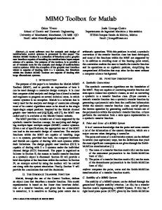
Fig. 4. First and second dialogues for building a controller ensuring a complex order behaviour for the open-loop, filled in. Clicking Third-generation CRONE control in the main dialogue, the first dialogue of Fig. 4 appears. It receives the parameters listed in section 4. As explained there, the controller is then to be reckoned using the functions of section 3. This cannot be immediately done because those functions do not work very well when they are given too many frequencies. So a second dialogue (shown in Fig. 4, below) is needed for the user to choose, among the frequencies used for fitting the parameters of (11), those where the behaviour of the desired controller is to be sampled (and the order which it will have). This task is not straightforward and requires human intervention. After the controller is obtained, the main dialogue will show the behaviour of the openloop. Furthermore, and since parameter variations were specified, the influence of these is shown as seen in Fig. 7. Actually it is always possible to view the effects of such changes by filling in the corresponding fields.
Cois, O., Lanusse, P., Melchior, P., Dancla, F. and Oustaloup, A. (2002). Fractional systems toolbox for Matlab: applications in system identification and Crone CSD. In: 41st IEEE conference on Decision and Control, Las Vegas. Hartley, T., and Lorenzo, C. (2003). Fractional-order system identification based on continuous orderdistributions. Signal processing, 83, 2287-2300. Oustaloup, A (1991). La commande CRONE: commande robuste d’ordre non entier. Hermès, Paris. Oustaloup, A., Melchior, P., Lanusse, P., Cois, O. and Dancla, F. (2002). The CRONE toolbox for Matlab. In: 41st IEEE conference on Decision and Control, Las Vegas. Podlubny, Igor (1999). Fractional differential equations. Academic Press, San Diego. Valério, D. (2001). Non-integer order robust control: an application. In: Student Forum, Porto, 25-28. Valério, D. and Sá da Costa, J. (2002). Time domain implementations of non-integer order controllers. In: Controlo, Aveiro, 353-358. Valério, D. and Sá da Costa, J. (2003a). Optimisation of non-integer order control parameters for a robotic arm. In: International Conference on Advanced Robotics, Coimbra. Valério, D.; Sá da Costa, J. (2003b). Digital implementation of non-integer control and its application to a two-link robotic arm. In: European Control Conference, Cambridge. Valério, D. and Sá da Costa, J. (2004). A method for identifying digital models and its application to non-integer control. In: Controlo, Faro. Vinagre, B.; Podlubny, I.; Hernández, A.; Feliu, V. (2000). Some approximations of fractional order operators used in control theory and applications. Fractional calculus & applied analysis. 3, 231248.
Fig. 5. The main dialogue, showing a Bode diagram of an approximation of a fractional order derivative.
Fig. 6. Dialogue for building a controller ensuring a real order behaviour for the open-loop.
Fig. 7. The main dialogue, showing a Nichols diagram and the effects of parameter variation.