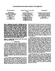
A Novel Algorithm for Asymmetrical Fault Detection in DFIG based Wind-Farm using Wavelet Singular Entropy Function Rahul Dubey,Ashok Tripathy, Senior Member IEEE, and Muhammad Ehtesham
Abstract— This paper proposes a novel technique for asymmetrical fault detection (LLL-G) in DFIG based wind farm using wavelet singular entropy function. In this study, there are six wind turbine driven DFIG are grouping together to make wind farm and 9 MW power is feeding to the grid. Further, the rotor is supplied by a bidirectional PWM converter for the control of active and reactive power flows from DFIG to the grid. In the case study, the three-phase fault is created in the grid and proposed algorithm detects the fault with in one and half cycles for 60 Hz system. A new diagnostic method based on the grid modulating signals pre-processing by Discrete Wavelet Transform (DWT) to derive singular values, used to find out Shannon entropy, called Wavelet Singular Entropy (WSE) is here proposed to detect grid faults dynamically over time. Simulation results demonstrate the effectiveness of the proposed approach under time-varying conditions. Index Terms— Doubly Fed Induction Generator (DFIG), Asymmetrical fault (LLL-G), Wavelet transform (WT), Wavelet Energy (WE).Wavelet Singular Entropy (WSE) I.
INTRODUCTION
in the area of fault diagnosis and condition RESEARCH monitoring of wind generators has generated keen interest as the clamor for renewable energy [1]–[5] becomes louder and clearer due to burgeoning oil prices. Wind generators used for high-power range (660 kW to 2 MW) are mainly woundrotor synchronous generators and doubly fed induction generators (DFIGs) [5]. Normally, 690-V DFIGs are used in this power range and relate to major market share [5]. The need for an accurate condition-monitoring and fault-detection method is high to reduce the operating and maintenance costs of wind energy systems. In Rahul Dubey is with Department of Electrical Engineering, National Institute of Technology, Rourkela-769008, India (email:
[email protected]) Ashok Tripathy is with Department of Electrical Engineering, Silicon Institute of Technology, Bhubaneswar-751024, India(email:
[email protected]) Muhammad Ehtesham is with Department of Electrical Engineering, National Institute of Technology, Rourkela-769008, India (email:
[email protected])
978-1-4673-0455-9/12/$31.00 ©2012 IEEE
particular, with plan of offshore installations, which makes it more inaccessible, it is vital to simultaneously increase reliability and service interval [1]. Like every electrical machine, wind generators are prone to electromechanical faults and require attention at the incipient stage to avoid escalation of the fault to cause a breakdown or major damage. Faults may occur in stator, rotor, bearings, air gap (eccentricity), etc. However, a literature survey shows that bearing faults and stator insulation breakdown cause the majority of machine failures [6], [7]. Induction-machine stator winding insulation degradation Is one of the major (about 40%) causes of machine failure [6]. Stator faults begin with degradation of the insulation between turns, and consequently, an interturn short circuit occurs. Fault-diagnostic methods for squirrel-cage induction motors have been researched extensively, and commercial systems for diagnosis of mechanical problems such as broken rotor bars us ing motor-current signature analysis (MCSA) and bearing faults using vibration analysis are available these days [4], [8]. However, fault diagnosis for DFIGs has remained little explored. Some research has already been conducted on stator interturn-fault diagnosis of DFIGs in the last five years, and a literature survey was made to explore existing methods. It suggests that existing techniques are based on vibration analysis [2] or MCSA of stator current [1] , [4], [10]. However, these methods have shortcomings due to the need of sophisticated vibration-sensing equipment that is partly invasive, requiring physical installation of sensors on the generator [4] or based on experimental results alone, [10] without complete theoretical basis and fail to prove reliable detections when the DFIG operates under imbalanced-load conditions [1], [4]. The control schemes used in DFIGs are typically of five types [11], but the most popular schemes are based on a DFIG with static Kramer drive and a DFIG with back-to- back converter [6]. DFIGs used as wind generators are grid connected and are frequently subjected to imbalanced load in three phases. Hence, it is essential to justify the existence of frequency used for fault detection with suitable theory and analysis in order to discover an unambiguous faultdetection technique in the presence of imbalanced load in DFIGs. The objective of this paper is to therefore develop a fault-diagnostic method that could be applied to any DFIG, irrespective of its control scheme, and provide unambiguous fault detection in spite of imbalanced loading. This paper is written in the following way. In section II, asymmetrical fault (LLL-G) detection methodology is
2 analyzed. Section III describes proposed WSE function for fault detection DFIG based wind farm. Section IV discusses the simulation results and conclusion is given in section V. II. DEFINITION OF WAVELET SINGULAR ENTROPY The definition of continuous WT for a given signal s (t) with respect to a mother wavelet ψ (t) is given as follows [13]: ∞
⎛ t −τ ⎞ Wτ ,m (t ) = s(t )Ψ⎜ ⎟ (1) ∫ m −∞ ⎝ m ⎠ Where m the scale is factor and τ is the translation factor. The coefficients of WT C (m,τ ) ) are defined by the following 1
inner product:
∞
C(m,τ ) = ∫ s(t ) •Wτ',m (t )dt
(2)
0
Generally, WT consists of successive pairs of low- and high pass filters. For each pair, the high-scale and low-frequency components are called approximations, while the low-scale and high-frequency components are called details. The approximations and details form the WT-coefficient matrix that we need. A. Singular Value Decompositions and Shannon Entropy The Singular Value Decomposition (SVD) for any m × n matrix A, m × r orthogonal matrix U , a transpose of an n × r orthogonal matrix V , and a r × r diagonal matrix Λ consequentially exist, which enable A to be equivalently represented in the SVD form as follows [14]
A = UΛV T Where And its diagonal elements
(3)
λi
(i = 1,2,3...., r ) are
called
“singular values” of matrix A the singular values are all nonnegative and arranged in a non-increasing order (i.e. λ1 ≥ λ 2 ≥ λ 3 ≥ ........ ≥ λ r > 0 ). If matrix A represents the
⎡ λ1 ⎢0 ⎢ Λ =⎢• ⎢ ⎢0 ⎢⎣ 0
0
•
0
λ2
•
0
•
•
•
0
•
λ r −1
0
•
0
0⎤ 0 ⎥⎥ •⎥ ⎥ 0⎥ λ r ⎥⎦
Time-frequency information of the transient, the matrix A will represent the basic modal characteristics of A. Therefore, we use SVD to analyze the obtained WT coefficient matrix and provide briefly numerical representation for the time– frequency distribution of the fault transient. Shannon’s entropy is an important uncertainty measure for evaluating structures and patterns of analyzed data. It is defined by Claude E. Shannon in 1948 as follows [12]. Let X = {x1 , x2 , x3 ,......xn } be a discrete random variable
with n whose
possible states. Let values
satisfy
P = {p1 , p 2 , p 2 ,......., pn }, the terms of 0 ≤ pi ≤ 1
and ∑ p i = 1(i = 1, 2 , 3 ....., n ) as the probabilities associated with those n states. The uncertainty information of each possible state
xi is
I ( xi ) = − log a pi
(4)
i = 1,2,3......, n
The Base-e logarithm will be used throughout this paper [14] [i.e. a = e ln (2 ) ]. We may call the information content of
X as self-information which is denoted as I(X ) . As the I ( X )
is a random variable, it is not suitable for measuring the uncertainty of the whole data. Therefore, the mathematical Expectation of I ( X ) is defined as entropy which is denoted by H ( X ) n
H ( X ) = E[I ( X )] = −∑ pi ln pi
(5)
i =1
B. Wavelet Singular Entropy (WSE)
The following procedures are carried out for computing WSE: 1) Process the current signal samples using WT, where the “db4” mother wavelet and 4-scaled WT are chosen in the transformation. Then, a 4 × n WTcoefficient matrix A can be obtained by means of (2). 2) The matrix A is decomposed with SVD in (4), and a singular-value array can be obtained as {λ1 , λ2 ,........, λr }, where r is the rank of the
diagonal matrix Λ . The value of r may be very large and the value of λi as well as its embodied information will decrease with the increase of i . 3) In order to obtain the entropy of the singular value array, the probability pi associated with λi is defined as follows:
pi =
λi
(6)
r
∑λ
j
j =1
4) Finally, the k ordered WSE of
s (t ) is obtained by (5)
k
WSEk = −∑ pi ln pi (k ≤ r )
(7)
i =1
Where k is the number of effective singular values involvedin the WSE calculation process. According to the aforementioned definition, WSE is used to map the correlative wavelet space into independent linearity space, and to indicate the uncertainty of the energy distribution in the time–frequency domain with a high immunity to noise. Due to its way of implementation, WSE is
3 sensitive to the transients produced by the faults, and the fewer modes the transients congregate to, the smaller the WSE is. Therefore, the proposed WSE will be suitable and useful for measuring the uncertainty and complexity of the analyzed signals, and will provide an intuitive and quantitative outcome for the fault diagnosis which can be utilized to overcome the drawbacks in the previous methodologies. III. PROPOSED WSE FUNCTION FOR FAULT DETECTION DFIG BASED WIND FARM The definition of WSE in Section II, we set the sampling frequency to be 20 kHz, take the 400-sample-long sequence in a time window as the input of WSE, and move this time window by a step of 400 samples. The order of WSE is chosen as k=4, 16, 32, 64. Consequently, the results of WSE at associated instants can be calculated. Start
Current data at relaying point (phase-a)
WT-coefficient matrix A, by (2)
Singular value of matrix A, by (3)
reactive power flows from DFIG to the grid. In the case study, the three-phase fault is created in the grid and proposed algorithm detects the fault with in one and half cycles for 60 Hz system. Relay
30KM
DFIG WindFarm
S B1
Fault
B2
Fig. 2 Simulated Systems Table I PARAMETERS OF THE TRANSMISSION LINE R1=0.1153 Ω/km
R0=0.413 Ω/km
L1=1.05X10⁻³ H/km
L0=3.37X10⁻³ H/km
C1=11.33X10⁻⁹ F/km
C0=5.01X10⁻⁹ F/km
Where R1: Positive Sequence Resistance R0: Zero Sequence Resistance L1: Positive Sequence Inductance L0: Zero Sequence Inductance C1: Positive Sequence Capacitance C0: Zero Sequence Capacitance 5
Iabc
Probability array P, by (6)
0 -5 0 3
W SEK
K-order WSE, by (7)
2
0.02
0.04
0.06
0.08
0.1
0.12
0.14
0.16
0.18
0.2
0.06
0.08
0.1
0.12
0.14
0.16
0.18
0.2
threshold
1 0 0
0.02
0.04
time(sec)
WSEK>Threshold
Fig.3. phase-A current (in p.u) and WSE8 results in (LLL-G) faults condition.(Rf=1Ω, LLL-G fault start at t=0.1sec and at t=0.12sec)
IV. SIMULATION RESULTS Yes
No No fault
Faulty phase involved Fig. 1 flow chart for the proposed WSE-function for fault detection in presence of DFIG wind-farm
The order of WSE influences the WSEk results. We can conclude after performing number of test that it is proper to choose k=8 in this paper, with enough precision and acceptable computing cost. ¾ Fault Detection Tests in Simulations In this study, there are six wind turbine driven DFIG are grouping together to make wind farm and 9 MW power is feeding to the grid. Further, the rotor is supplied by a bidirectional PWM converter for the control of active and
Fig. 2 shows the system selected for simulation. The system details are given in the Table-II. The system is simulated through MATLAB computer simulation package. The sending end (SE) is modeled as an equivalent machine and the receiving end (RE) is modeled as a DFIG wind-farm. The corresponding results are presented here. All the simulation result is taken for RF=10Ω and faults duration t=0.08sec to 0.12sec.
4 -4
x 10 5 0 -5 -3 0x 10 0.02 1 0 -1 0.02 0.010 0 -0.01 0 0.02 0.1 0 -0.1 0 0.02 0.2 0 -0.2 0 0.02 0.05 0 -0.05 0 0.02 0.1 0 -0.1 0 0.02 d1
1.5
0.06
0.08
0.1
0.12
0.14
0.16
0.18
0.2
0.04
0.06
0.08
0.1
0.12
0.14
0.16
0.18
0.2
0.04
0.06
0.08
0.1
0.12
0.14
0.16
0.18
0.2
1 0.5 0 -0.5
d4
d3
V-stator(p.u)
d2
0.04
0.06
0.08
0.1
0.12
0.14
0.16
0.18
0.2
0.04
0.06
0.08
0.1
0.12
0.14
0.16
0.18
0.2
0.04
0.06
0.08
0.1
0.12
0.14
0.16
0.18
0.2
0.04
0.06
0.08
0.1 0.12 time(sec)
0.14
0.16
0.18
0.2
-1
d5
0.04
-1.5 0
0.02
0.04
0.06
0.08
0.1 0.12 time(sec)
0.14
0.16
0.18
0.2
d6
Fig. 8. Stator voltage during LLL-G faults
d7
4
I-rotor(p.u)
2
Fig.4. Wavelet- d1 to wavelet-d7 decompose signal
0 -2 -4
5
Ia b c
-6 0
0
0.04
0.06
0.08
0.1 0.12 time(sec)
0.14
0.16
0.18
0.2
0.14
0.16
0.18
0.2
0.16
0.18
0.2
Fig. 9 rotor current signals during LLL-G faults
-5 0 0.1
0.02
0.04
0.06
0.08
0.1
0.12
0.14
0.16
0.18
1
0.2
0.5
0
-0.1 0 2
W SEK
0.02
0.04
0.06
0.08
0.1
0 0
0.02
0.14
0.16
0.18
0.2
fault
threshold
1
0.12
no fault 0.04 0.06
0.08
0.1
0.12
I- grid(p.u)
D7
0.02
0
-0.5
0.14
0.16
0.18
0.2
-1 0
time(sec) Fig.5. 3-phase current (in p.u), wavelet-d7detailed coefficient and WSE8 results in (LLL-G) faults condition
0.02
0.04
0.06
0.08
0.1 0.12 time(sec)
Fig. 10 grid current signals during LLL-G faults 4 3
2
P Q
1.5
2 Ia(p.u)
1
P & Q( in p.u)
1
0 -1
0.5
-2
0
-3 -4 0
-0.5 -1 0
0.02
0.04
0.06
0.08
0.1 0.12 time(sec)
0.14
0.16
0.18
0.2
0.02
0.04
0.06
0.08
0.1 0.12 time(sec)
0.14
0.1 0.12 time(sec)
0.14
Fig. 11 Phase-a current signal at relay end during LLL-G faults 4
Fig. 6 P (active power) and Q (reactive power) during LLL-G faults
3 4
2 2
Ib(p.u)
I-stator(p.u)
1 0
0
-2
-1
-4
-2
-6 0
-3 0.02
0.04
0.06
0.08
0.1 0.12 time(sec)
Fig. 7. Stator current during LLL-G faults
0.14
0.16
0.18
0.2
-4 0
0.02
0.04
0.06
0.08
0.16
0.18
Fig. 12 Phase-b current signal at relay end during LLL-G faults
0.2
5 method based on the grid modulating signals pre-processing by Discrete Wavelet Transform (DWT) to derive singular values, used to find out Shannon entropy, called Wavelet Singular Entropy (WSE) is here proposed to detect grid faults dynamically over time. From the simulation results, we could observe that, the proposed method not only detects the fault within one and half cycle of fundamental wave, also it reveals the effectiveness under time- varying conditions.
4 3 2 Ic(p.u)
1 0 -1 -2 -3 -4 0
0.02
0.04
0.06
0.08
0.1 0.12 time(sec)
0.14
0.16
0.18
0.2
Fig. 13 Phase-c current signals at relay end during LLL-G faults 1.22
Fault Types
1.215 1.21
TABLE-II FAULT SITUATIONS TESTED USING THE PROPOSED WAVELET SINGULAR ENTROPY Fault Fault Fault Power Response resistance location inception angle time (ohm) (km) angle (degree) (cycles) (degree)
wr
1.205 1.2
a-b-c
1.195 1.19 1.185 0
0.02
0.04
0.06
0.08
0.1 0.12 time(sec)
0.14
0.16
0.18
a-bc-g
0.2
Fig. 14 wr signals during LLL-G faults -0.6
10
60
30
45
1.50
100
170
45
60
1.54
20
50
45
60
1.50
100
160
60
45
1.53
a-b-g
10
85
90
60
1.50
b-c-g
50
120
45
45
1.55
c-a-g
100
180
60
60
1.54
a-b
20
30
45
45
1.50
Tm
-0.65
-0.7
-0.75
-0.8 0
0.02
0.04
0.06
0.08
0.1 0.12 time(sec)
0.14
0.16
0.18
0.2
b-c
50
90
60
60
1.54
c-a
100
160
30
45
1.53
a-g
0
20
30
45
1.50
b-g
50
130
60
45
1.54
c-g
100
180
30
60
1.55
Fig. 15 Tm (mech. torque) signals during LLL-G faults
REFERENCES 0.5
[1]
0
Tem
-0.5 -1 -1.5 -2 -2.5 -3 0
0.02
0.04
0.06
0.08
0.1 0.12 time(sec)
0.14
0.16
0.18
0.2
Fig. 16 Tem (elec. mag. torque) signals during LLL-G faults
V. CONCLUSIONS In this paper, a new technique for detecting asymmetrical fault (LLL-G) in presence of a DFIG has been studied by analyzing the current signal at relay end and the effectiveness of a new and reliable approach for the characterization of asymmetrical fault (LLL-G) in time varying condition is observed. The proposed approach is based on an optimized use of the DWT by a simple pre-processing of the variables to be analyzed. In the case study, the three-phase (LLL-G) fault is created in the grid and proposed algorithm detects the fault with in one and half cycles for 60Hz system. A new diagnostic
L. M. Popa, B. B. Jensen, F. Ritche, and I. Boldea, “Condition monitoring of wind generators,” in Conf. Rec. IEEE IAS Annu. Meeting, Oct. 2003, vol. 3, pp. 1839–1846. [2] P. Caselitz, J. Giebhardt, T. Kruger, and M. Mevenkamp, “Development of a fault detection system for wind energy converters,” in Proc. EUWEC, Göteborg, Sweden, 1996, pp. 1–4. [3] Q. F. Lu, C. T. Cao, and E. Ritche, “Model of stator inter-turn short circuit fault in doubly-fed induction generators for wind turbine,” in Proc. 35th Annu. IEEE PESC, Jun. 2004, vol. 2, pp. 932–937. [4] I. Albizu, A. Tapia, J. R. Saenz, A. J. Mazon, and I. Zamora, “Online stator winding fault diagnosis in induction generators for renewable generation,” in Proc. 35th Annu. IEEE PESC, Jun. 2004, vol. 2, pp. 932–937. [5] L. H. Hansen, L. Helle, F. Blaabjerg, E. Ritche, S. Munk-Nielsen, H. Bindner, P. Sorensen, and B. Bak-Jensen, “Conceptual survey of generators and power electronics for wind turbines,” Risø Nat. Lab., Rockilde, Denmark, Dec. 2001. [6] S. Nandi and H. A. Toliyat, “Fault diagnosis of electrical machines a review,” in Conf. Rec. 34th IEEE IAS Annu. Meeting, 1999, vol. 1, pp. 197–204. [7] P. Vas, Parameter Estimation, Condition Monitoring, and Diagnosis of Electrical Machines. Oxford, U.K.: Clarendon, 1993. [8] H. Douglas, P. Pillay, and P. Barendse, “The detection of inter-turn stator faults in doubly-fed induction generators,” in Conf. Rec. 40th IEEE IAS Annu. Meeting, Oct. 2–6, 2005, vol. 2, pp. 1097–1102. [9] T. Wildi, Electrical Machines, Drives, and Power Systems, 6th ed. Englewood Cliffs, NJ: Prentice-Hall, 2005. [10] W. T. Thomson, “On-line MCSA to diagnose shorted turns in low voltage stator windings of 3-phase induction motors prior to failure,” in Proc. IEEE-IEMDC , 2001, vol. 1, pp. 891–898.
6 [11] J. A. Baroudi, V. R. Dinavahi, and A. M. Knight, “A review of power converter topologies for wind generators,” in Proc. IEEE Int. Elect. Mach. Drives, May 15–18, 2005, vol. 1, pp. 458–465. [12] C. E. Shannon, “A mathematical theory of communication,” Bell Syst. Tech. J., vol. 27, pp. 379–423, 623–656, Jul., Oct. 1948. [13] Z. Y. He, X. Q. Chen, and G. M. Luo, “Wavelet entropy measure definition and its application for transmission line fault detection and identification (part I: Definition and methodology),” in Proc. IEEE Int. Conf. Power System Technology, Oct. 2006, pp. 1–6. [14] V. C. Klema and A. J. Laub, “The singular value decomposition: Its computation and some applications,” IEEE Trans. Autom. Control, vol. AC-25, no. 2, pp. 164–176, Apr. 1980. [15] J. Upender, C. P. Gupta and G. K. Singh, “Discrete wavelet transform and probabilistic neural network based algorithm for classification of fault on transmission systems,” in India conf., IEEE,INDICON 2008,11-13 Dec,2008, Vol.1, pp. 206-211. [16] Zhengyou He, Ling Fu, Sheng Lin and Zhiqian Bo,’ Fault Detection and Classification in EHV Transmission Line Based on Wavelet Singular Entropy” IEEE Transactions on Power Delivery, Vol. 25, No. 4, October 2010. [17] A. A. Hajjar, M. M. Mansour, and H. A. Talaat, “High-phase order power transmission lines relaying approach based on the wavelet analysis of the fault generated traveling waves,” in Proc. 39th Int. Univ. Power Eng. Conf., 2004, vol. 1, pp. 805–809. [18] A. I. Megahed, A. M. Moussa, and A. E. Bayoumy, “Usage of wavelet transform in the protection of series-compensated transmission lines,” IEEE Trans. Power Del., vol. 21, no. 3, pp. 1213–1221, Jul. 2006. [19] J. D. Duan, B. H. Zhang, and H. X. Ha, “A novel approach to faulted phase selection using current traveling waves and wavelet analysis,” in Proc. Int. Conf. Power System Technology, 2002, vol. 2, pp. 1146–1150. [20] Q. L. Su, X. Z. Dong, Z. Q. Bo, and F. Jiang, “New approach of fault detection and fault phase selection based on initial current traveling waves,” in Proc. IEEE Power Eng. Soc. Summer Meeting, 2002, vol. 1, pp. 393–397.