repairs. The modelling language has been used to describe a simple web based ... tools are obviously helpful in managing the computer resources used to.
A Novel Algorithm for Fault Diagnosis in Internet-based Services Adrian Baldwin, Claudio Bartolini, Giuliano Di Vitantonio, Kave Eshghi
c
{ajb, clb, gdv, ke}@hplb.hpl.hp.com
c Hewlett-Packard Laboratories, System Management Department Filton Road, Stoke Gifford, Bristol - United Kingdom
Abstract The Internet provides a mechanism for the delivery of many different types of services including traditional business transaction processing as well as new E-Commerce services. The acceptance of these services is dependent on their delivery in a secure and reliable fashion. Till now there has been little emphasis on the overall management of these services to ensure their reliability. This paper concentrates on the problem management aspects of the service and in particular on monitoring and diagnosing services down from the service level onto the underlying computer resources. Within the system management department at HP Labs Bristol a - Dolphin based - tool has been developed that provides an integrated framework for resource discovery, monitoring and diagnosis. This tool is based on model based reasoning and provides an object oriented logic programming language in which system resources and services can be modelled. This paper describes an inferencing technique which provides a diagnostic mechanism leading to a compact explanation of a fault under the assumption of a single point of failure. The algorithm uses two components: a partial evaluation of the inference tree and an assumption based truth maintenance system (ATMS) to direct further exploration. Further work is in progress to investigate the use of the diagnostic explanations as a basis for policy driven automated repairs. The modelling language has been used to describe a simple web based service, as well as the resources used in its implementation. The algorithm has been exercised in the diagnosis of failures at the service level, exploring the mapping onto failures in the individual components used to provide the service.
1.0
Introduction
There are already a large number of services provided over the Internet allowing users to perform a variety of tasks from simple information gathering to obtaining access to databases, news services through to banking and shopping services. The Internet can also provide a mechanism for the delivery of information services within the extended enterprise and as such have the potential to replace current EDI systems. As these services increase in both complexity and number it is critical that there is a sufficient set of management tools to ensure these services can be run in a reliable and secure manner. Current system management tools are obviously helpful in managing the computer resources used to provide these services. The system manager does, however, need to be able to function at the service level that is they must be able to see the systems from a user's point of view. As such, it is necessary to build on the conventional system management tools in order to change the system manager's view and to enhance productivity when managing services running on a complex set of hardware.
1.1
Service Management
The notion of a service is integrally linked to the user being served and, therefore, the service can be described in terms of a series of interactions between the service and the user. As such service management tools must contain service level knowledge such as how the system is used and the importance of each of the components as well as the traditional system management knowledge about
1
the underlying computer systems. Any management tool must have information from these two different view points as well as providing a mapping to reconcile the views. The page organisation in a web based service provides important clues to the structure formed by individual or small groups of service interactions contained in a web page. In order to perform service management on a large service it becomes necessary to build up these individual interactions into abstract composite interactions performing a higher level service. The mapping between this high level service view and the system view is also relatively well defined with a URL specifying the machine serving the information along with the position of the information. Where pages are formed dynamically or involve interactions it is possible to extract information about some of the processes involved. These factors mean that a web based service provide a good starting domain to study service management although it is hoped that much of the methodology is relevant to other, less standardised, methods of service delivery.
1.2
Automated management of services
A critical factor in the cost of management is the amount of and level of human expertise required which must be offset against the cost of the service being partially or totally unavailable. This means that as services and the systems on which they run become more complex the traditional heavy reliance on the knowledge of the system administrator clearly becomes inadequate. In fact, as services become more complex, provided on shared resources and far more intertwined it will become increasingly difficult for even the most skilled system manager to respond to malfunctions in a quick and efficient manner. Ideally an integrated management solution would provide a degree of automation over the whole management cycle from initial installation/configuration, monitoring, maintenance, change and reconfiguration. It is believed that the most beneficial area for automation is that of maintenance, that is fault detection, diagnosis and repair. The cost of ownership would be dramatically reduced by a solution that detected faults and disruptions, identified their cause and produced a fix to bring the service back into an acceptable state. A critical requirement in automating the maintenance cycle is the ability to automatically produce a correct and precise diagnosis that can pin point the problem and provide information to trigger a suitable repair plan. The work presented in this paper concentrated on the use of model based reasoning to provide such an algorithm.
2.0
Model-based diagnosis
The research area of diagnosis is traditionally one of the most challenging. The strong need for solutions to practical problems in medicine, mechanics and electronics has been the driver for several efforts in this area. In particular, people have been looking at AI techniques as the most promising way to tackle problems. Several AI communities have been very actively involved in diagnosis, and have delivered some good solutions. Unfortunately, these are usually customised to the problems that they are trying to solve. Most of the efforts have been produced in areas like electrical circuits, mechanical systems and medical diagnosis. One of the best known attempt of generalisation is de Kleer and Williams’ General Diagnostic Engine (GDE) [1]. Anyway there have been very few attempts at trying to apply AI diagnostic techniques to the problems that we face in network and systems management domain. Our work at HP Labs Bristol, in the System Management Department, is one of these attempts and is well underway. A tool has been developed that provides an integrated framework for resource discovery, monitoring, diagnosis and configuration. This tool, called Flipper, is based on model based reasoning and provides an object oriented logic programming language in which system resources and
2
services can be modelled. Flipper is an evolution of the Dolphin prototype [2], that represents the core technology around which OpenView IT/A was developed. Flipper was originally built on the experience developed with IT/A, which is a product for resource discovery and configuration, so its diagnostic capabilities were quite limited. Over the past few months we have been working on a new diagnostic algorithm that significantly enhances the diagnostic capabilities of Flipper. The decision to build the management functionality framework on model-based reasoning was made several years ago, but it is proving to be a particularly long-sighted choice for diagnosis. In fact, model-based reasoning is emerging as one of the most successful AI techniques to solve diagnostic problems. Such a technique is based on the assumption that the correct functioning of the system can be captured in a model, and checked against the real functioning in order to detect discrepancies. Many algorithms based on this principle have been proposed in the model-based diagnosis community, though none of them has been successfully applied to the area of system management. For this and other reasons, the algorithm presented in this paper represents an original approach to model-based diagnosis. The algorithm uses most of the features already present in Flipper (e.g. the same modelling language and the same data structure), providing a nice and smooth integration with the rest of the management functionality. An extension to the inference engine was introduced to tailor the reasoning to the diagnostic requirements. The rule-based approach provides the nice feature to pinpoint the problem to a sufficient level of detail to trigger a pre-compiled repair plan. Further research is going on to introduce some more reasoning capabilities in the generation of the repair plan. The remainder of this paper describes the diagnostic algorithm in more detail as well as demonstrating its effectiveness as a tool for finding problems with a web service.
3.0
The Diagnostic Algorithm
The algorithm uses Flipper Modelling Language (FML) [3] and shares most of Flipper’s data structures. In order to tailor the reasoning to the diagnostic requirements, the inference engine has been enhanced by adding the capability of partial evaluation [4] and by tightly coupling it with a lightweight Assumption Based Maintenance System (ATMS) [5].
3.1
Flipper
Flipper is a prototype aimed at applying model based reasoning to a variety of system management tasks. An object orientated modelling language allows classes of manageable objects to be defined; methods written as declarative logic rules allowing the various properties of an object to be described as well as relationships between these objects. It is usually possible to classify these model rules into three broad categories: discovery rules to find instances of manageable objects; attribute rules that provide information about an object; and rules, such as diagnostic rules, describing correct object states. There are further action rules written in a more deterministic language allowing the state of an object to be changed. Flipper provides an inference engine with a backward chaining mechanism for reasoning about models allowing manageable objects to be discovered, queried and have their status checked. The system is built on an extensible architecture allowing plug in access modules to access system instrumentation and functions. The diagnostic algorithm provides an important capability in that it produces an explanation of why an object is considered faulty.
3
3.2
Diagnosable nodes
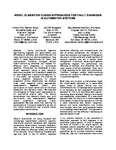
A model based diagnosis engine takes a model describing the set of valid states of an object (or a collection of objects) and compares them to the state of an actual system. The logic based diagnosis rules describe various elements of an object, or a relationship between several objects, along with valid relationships which can be obtained from other system objects. These diagnostic rules are organised into a hierarchy which involves describing ever more detailed system states. For example a top level model of a printing service would check each component (e.g. the driver, connection, and printer) by calling on diagnosis rules for each component. Much of the body of each rule is concerned with discovering and refining the exact element to be checked, validating whether which diagnostic rule applies to that object, and in doing basic comparisons. A diagnosis could be provided by reporting the full diagnosis path; however, these rule components would serve to obscure the basic reasons for failure. The proposed diagnostic algorithm relies on semantic (DIAGNOSABLE) tags in the model which specify that a particular relation is meaningful as part of a diagnosis. That is they identify the rules that check a systems state allowing discovery, attribute and processing rules to be ignored For example, when diagnosing the printer service most of the failed proof path contains information such as methods of obtaining the location of printer drivers, the fact that the printer is not connected via the parallel port, or even that the string “HP Laserjet 4Si” does not match “HP Deskjet 1200C” all of which do little to identify the real problem. All that is of interest is that there is a problem with a printer driver because a HP Laserjet 4si driver is being used with a HP Deskjet 1200C. The diagnosable tag provides a mechanism for the model writer to specify these important elements of a diagnosis. In effect an abstract diagnostic search space (See Figure 3-1 and 4-1) has been defined on top of the real search space defined by the complete rule set. The search engine must still search this full tree but the diagnostic engine projects this tree onto the more meaningful representation of the diagnostic search space. non diagnosable diagnosable
GetPrinter Config
Locally Spooled
Driver Exists
AND DriverOk ConnectionOk PrintSystem IsOk
Driver correct for printer
Offline
OR PrinterOk
PrintSpoolerOk
AND
Not
OR
Outof Paper
Outof Toner
Remotely Spooled
Figure 3-2 The search space for a printer check showing a diagnosis in the form of a sub tree.
4
3.3
Description of the algorithm
The diagnostic algorithm takes a flipper query about the state of a managed object and produces a diagnosis which is a sub-tree from the overall diagnosis tree (See Figure 3.1). This sub-tree represents a single point of failure, that is, it contains only those nodes required to identify a single fault; of course an empty sub-tree will be produced when no diagnosable fault is found. This sub-tree contains ever more detailed diagnosis nodes (printSystemIsOk, to driverCorrectForPrinter) each representing some aspect of the system that is incorrect. At any level, a sub-tree is a diagnosis for its root node in the same sense as the diagnosis tree as a whole is a diagnosis for the goal thereby leading to a recursive algorithm. The complete sub-tree is a failure diagnosis, however, where negations occur it can also include success diagnoses (printerIsOk) as sub-tree. The diagnosis is, of course, recursive and therefore the success diagnosis can include both failure and success diagnoses. An assumption has been made that all diagnosis nodes must be fully bound. This assumption is made to ensure that the diagnosis problem is fully specified thereby ensuring failures are due to problems with the managed object rather than problems in obtaining an object’s attributes. A query that states what is wrong with the printer does not fully specify the problem and is therefore not diagnosable. The correct query would ask why a particular user on a particular machine could not use a given printer it is only when all this information is given that the full diagnosis can be performed. The algorithm for the failure diagnosis consists of the recursive intertwining of two phases. These are: first level diagnosis and selection of candidates to diagnose. 3.3.1
First level diagnosis
The first level diagnosis aims to identify all the diagnosable nodes at that level forming them into a disjunction of conjunctions containing fully bound diagnosable nodes. In other words the diagnosis search space is being expanded by one level. A typical diagnosis model rule (G) can be rearranged into the general form: G IF P1 & P2 & … Pn & ( (P1 1 & …P1j &D11 & ..D1n) OR (P21 & …P2k &D21 & ..D2m) OR … (Pv1 & …Pvl &Dv1 & ..Dvo)) (1) Where Px and Pxy are non diagnosable nodes that discover information, get and process objects' attributes or perform relevance checks. In figure 3-1 these include the nodes getPrinterConfig which obtains information about the printer and locallySpooled which checks that the diagnosis elements in that part of the rule apply to the printer object. The Dij are the diagnosable nodes defining the diagnosis tree. In some cases the same diagnosable will occur at different points in the rule that is Dij = Def (e.g. PrinterIsOk). This initial part of the algorithm aims to obtain the structure: ( (D11 & ..D1n) OR (D21 & ..D2m) OR … (Dv1 & ..Dvo))
(2)
The structure (2) is now a collection of possible reasons for the goal to fail. It is assumed that the goal has failed and therefore at least one node in every conjunct will have failed. The first step towards reaching this structure is to evaluate the non diagnosable components of the rule using the standard Flipper inference engine. This stage of the algorithm is a partial evaluation where the normal proof process is continued except when encountering a diagnosable node which is pushed onto a (conjunct) stack associated with the proof stack. Backtracking is performed by consistently popping this conjunct stack. This process has explored an OR branch of the possible proof path evaluating all the nondiagnosables and creating a stack containing the conjunction of diagnosable elements that must be true for this branch to be true. The process then commits to the contents of the conjunct stack and continues to explore other OR branches committing the conjunct stack after each successful branch. 5
After all these OR branches have been explored a disjunction of conjunctions has been obtained and under the assumption of failure one node in each conjunction is assumed to have failed. An empty stack when the commit is reached indicates that a real solution (without diagnosables) has been found and therefore the failure assumption is false. Alternately if the commit stage is never reached this indicates that there is a failure in a non diagnosable element of the goal and no further diagnosis is necessary. The algorithm is further complicated when a negative proof is encountered when a commit is not performed on the stack contents, since: 1) the negated expression was not a diagnosable relation (we would have stopped otherwise) 2) the success of the negated relation means the failure of the not expression, which will cause this OR branch to fail.
DriverOk
ConnectionOk
AND PrinterOk PrintSystem IsOk
OR PrinterOk
AND
PrintSpoolerOk
Figure 3-2 First-level diagnosis for the printer diagnosis shown in figure 3-1 Figure 3-2 shows the results of the first stage of the algorithm on the printer example from figure 3-1 showing a disjunction of conjunctions containing diagnosable nodes. It should be noted that in reality this result should not be obtained because the printer will not be spooled both locally and remotely. 3.3.2
Selection of candidates to diagnose
At the end of the first level diagnosis, the control is given back to failure diagnosis and the algorithm enters the ATMS mode. The output of the first phase is a disjunction of conjunctions. We know that:
1) all conjuncts failed 2) at least one term in each conjunct failed Since we deferred the evaluation, we still do not know which term(s) has actually failed in each conjunct. For clarity purposes in this section we will refer to the diagnosable relations in the conjunct as candidates or assumptions, depending on the context. The algorithm proceeds with the selection of a minimal set of candidates. The assumption underlying here is that the more often one candidate is recurring (the same candidate may occur in several conjunctions - see 4.3.1) the more likely is that it’s responsible for the failure. The minimal set of candidates must anyway cover all conjunctions in the disjunction. A more advanced selection 6
mechanism could be based on fault frequency analysis selecting nodes representing the most common failures first. In the printSystemIsOk example the first stage produces the disjunction shown in figure 3-2. Diagnosing a more general goal G may result a disjunction of conjunctions such as that below: (A and B and C) or (A and B and D) or (A and C and E) or (D and E) where A,B,C,D,E are all fully bound diagnosable relations. Suppose that B and E are the goals that actually failed. The algorithm chooses A as a most likely candidate. At this point the failure diagnosis procedure is called recursively on A. This can involve further first level diagnoses on sub-goals, candidate selections and so on using a recursive process until the validity of the goal has been proved. At this stage A has been proved true; it is therefore not part of the diagnosis and is removed from each conjunction in which it appears. The disjunction is updated to: (B and C) or (B and D) or (C and E) or (D and E) The algorithm chooses now B as a most likely candidate. After the recursive diagnosis B fails, and we have found a reason for the failure of the first two conjuncts. Thanks to the recursion, the algorithm returns B with all its sub-diagnoses. Every conjunction falsified by B is deleted from the disjunction which is updated to: (C and E) or (D and E) This time we proof E and its failure gives us an empty disjunction. At this point the procedure returns B (with its sub-diagnoses), E (with its sub-diagnoses) as a sub-diagnoses for the given goal G. The diagnosis will be G B … {sub-diagnoses for B} E … {sub-diagnoses for E} In the case of the printer system the example diagnosis is shown in figure 3-1 only one conjunction is committed at any node.
4.0
Service Diagnosis Example
The printer example above provides a diagnosis of a computing resource, a printer, it is also possible to apply the diagnosis algorithm to a model describing a service. A computing resource can be seen from different view points; it can be seen as a number of component resources such as computer systems and applications that form an overall resource; or it can be viewed as a service that allows a user to perform a task. The resource centred view is traditional for IT where the technology has often become the major focus, however, in a more cost conscious world the emphasis is changing to the user or service view. The world wide web (WWW) has increased this emphasis in that there is a clear interface which hides way the service is delivered and concentrates on the information provided to the user or the transaction performed by the user. This means that a service manager must change the point at which they start performing a diagnosis to the way that the user interacts with the service.
7
An example of a simple web based service such as an electronic support centre (ESC) can be used to demonstrate how a service could be modelled allowing the use of MBR techniques for monitoring and diagnosis. An electronic support centre is a service that allows customers to obtain the latest drivers, software patches and product information. As such, in its simplest form, it will consist a considerable amount of information organised onto web pages, some files that can be down loaded as well as the computing resources needed for the web server. More complex versions of the ESC could contain search engines; allow users to register; dynamically form the content of pages from a database; and it could even contain E-Commerce support for direct sales. For the purposes of this paper it is considered sufficient to consider the simple case whilst considering how the techniques are extendible to the more complex situations. From a traditional system management point of view this ESC would consist of a computer system, networking components, a file system and a web server application all of which must be managed. When a fault is detected the system manager could use a diagnostic mechanism to diagnose the high level component that is believed to be causing the fault. A service management system manages the same components but using has a different abstraction allowing the manager to investigate faults a user has with the whole service or individual service components (interactions). There are two basic types of interactions available to the user of the simplest form of the ESC, firstly they can browse through indexes and follow hyper links and secondly they can retrieve various bits of information (including new drivers and patches). Failures of these two types of interactions could lead to user problem reports such as: I cannot reach information about Product X from the contents Z. I obtained the wrong information from the contents Z I cannot download the page about product The information about product X is wrong. For the first three of these queries the service manager would need to perform some diagnosis to find out why that part of the service is failing. The fourth query is with the real service content which is not the service manager's responsibility all that can be done is to pass on the problem to the author of that part of the service. The first problem for a service manager, or an automated system, is to formalise these queries so that a full formal specification of the problem. In this case they need a description of the user (i.e. name, IP address) as well as a more formal description of the piece of information that the user is trying to access (the URL). In the case of problems reaching one page from another both URLs will be necessary. This allows the service manager to formulate a set of standard queries allowing a model based reasoning system to dig down to the resource level to find the problems.
4.1
Diagnosing a service element
The simplest query for a web based service that describes the service level view is a relation that describes the ability of a user to access a particular web page which contains the information in which they are interested. It is this elemental service level query that is used to form a mapping between the service level request and the resources used to serve that request. This query has been written in the flipper language as: [User u] isOkToAccess [URL info_page] This query is in the form of a relation that associates a particular instance of a user object containing user and machine names with a URL which is the string displayed on the user's web browser. There will be one or more rules that can unify with this pattern and the diagnostic algorithm described in the previous section uses this rule and other rules and relations in the model set to produce a diagnosis.
8
Config Security Admit User
Usr Default
Usr Access
Usr Page Control
Usr Access
Default
Access
Config ~database
Allowed AccessTo Security Admit Machine
IPAddr DNS
Page Control
isOkTo Access
~database
Access
IPAddr DNS
WebServer Ok WebPage Ok
Httpd Exists Httpd Running Exists
PageFiles Ok
Not
Component Ok
Bad File
accessible
Figure 4-1 An example diagnostic tree showing the search space for the isOkToAccess query. Figure 4-1 shows the diagnosis tree for this simple interaction query. The diagnosis algorithm will explore the possible failure routes such as checking security access, the web server and the existence of the page of interest. As described the diagnosis algorithm leads from the high level problem descriptions into relations that give more detail about the problem. The result of this query should be a sub-tree representing the path from the service level query to the system problem. A more complex service example, for example if the ESC allowed a user to register their use of a product, would require more complex models. In this case the element that checks the HTML page to find component files (such as images) could also look for HTML form directives and further models would diagnose the associated CGI scripts. A registration form would probably be linked, using this CGI script, to a database containing user information. In this case the register CGI script model would lead into the diagnosis of the database system along with the computer systems on which it is running.
4.2
Results
The diagnostic algorithm has been tested using this service level query that checks a user's ability to access one particular service element. Testing has involved creating a number of problems with the simple electronic support centre service and then using the diagnostic mechanism to pin point each problem. The variety of scenarios tested included faults such as individual users not being authorised, pages being inaccessible or missing, and the server crashing. In each case the diagnostic algorithm identifies the faults and shows the meaningful diagnosis containing fully bound relations that occur in the failure path. An example scenario is shown here to show the type of output that results from algorithm. In this example a user (u1 on a machine called umach.fault.com) encounters a problem when trying to access information about a video driver for a Vectra PC which is contained in a web page at “http://www.esc.com/vectra/vidDriver.htm”. The service administrator uses the flipper system to describe user's problem by asking the query:
9
[User ] isOkToAccess [Url