Control (DTC) algorithm for induction motor drive is proposed and tested. ... servo loop results in a response speed and the resulting bandwidth that are inferior ... and ripple â free response of the electromagnetic torque; while reducing ..... Flux Ripple in DTC Schemes for Induction Motorsâ, IEEE-IAS Annual. Meeting 2002.
A Novel Direct Torque and Flux Control Algorithm for the Induction Motor Drive Petar R. Matic
Branko D. Blanusa
Slobodan N. Vukosavic
Faculty of Electrical Engineering 5 Patre Banja Luka 78 000, Rep. of Srpska Bosnia and Herzegovina
Faculty of Electrical Engineering 5 Patre Banja Luka 78 000, Rep. of Srpska Bosnia and Herzegovina
Faculty of Electrical Engineering Bul. Kralja Aleksandra 73 Belgrade 11 000 Serbia and Montenegro
Abstract1- In this paper a new sensorless Direct Torque Control (DTC) algorithm for induction motor drive is proposed and tested. This algorithm provides decoupled control of the torque and flux with constant inverter switching frequency and a minimum torque and flux ripple. Compared to the other DTC methods, this algorithm is much simpler and has less mathematical operations, and can be implemented on most existing digital drive controllers. Algorithm is based on imposing the flux vector spatial orientation and rotation speed, which defines the unique solution for reference stator voltage. The implementation of the control scheme using DSP – based hardware is described, with complete experimental evidence and the straightforward implementation instructions.
torque and flux comparators. In turn, this results in a large torque ripple unless a very short sampling time (below 25µs) is provided [5-7]. DTC based on the deadbeat (inverse) solution to the machine equations utilize an inverse model to calculate the theoretical voltage vector needed to move the machine torque and stator flux to the desired values in one sample period. This voltage vector is then synthesized over the sample period by the use of Space Vector Modulation (SVM) techniques. However, the calculation of the voltage vector requires the solution of a quadratic equation, which results in two solutions and an optimal solution must be determined. In transient conditions, said quadratic equation has no solution and therefore the alternative schemes, based on look – up tables or torque limitation have to be provided [8-14]. In this paper a novel direct torque algorithm is proposed for the control of the torque and flux of an induction motor, running both in the flux weakening and the constant torque modes and performing well in both the steady state and the transient states. The algorithm is focused on getting a smooth and ripple – free response of the electromagnetic torque; while reducing parameter dependence and the number of parameters required; preserving a certain simplicity and ease of implementation on most existing digital drive controllers. In principle, the proposed approach relies on the intrinsic properties of an induction motor. Namely, generated torque is proportional to the square of the flux linkage and to the relative speed of the flux vector with respect to the rotor itself. Accelerating the flux rotation relative to the rotor contributes an increase in torque. In the algorithm, the flux vector angular advancement is divided in two parts: i) the angle increment ensuring steady – state rotation and ii) the angle increment corresponding to the flux acceleration. The later should be kept on the zero value if no torque changes are required. Positive and negative values of the later angular component correspond to the torque increment or decrement, respectively. In addition to increasing the tangential component of the flux linkage, the radial component is asserted as well, controlling the flux amplitude according to the operating speed and load. In the paper, the algorithm for the calculation of desired flux increments according to desired change in torque and the implementation aspects of voltage command calculation are explained in detail. Presented results are supported by the simulation and experimental evidence.
I. INTRODUCTION High performance electric drives require decoupled torque and flux control. This control is commonly provided through Field Oriented Control (FOC), which is based on decoupling of the torque – producing current component and the flux – producing component. FOC drive scheme requires current controllers and coordinate transformations. Current – regulated pulse – width – modulation (CRPWM) inverter and inner current loops degrade the dynamic performance in the operating regimes wherein the voltage margin is insufficcent for the current control, particularly in the field weaking region. Besides, the existence of the cascaded controller structure where the flux and torque controllers reside in the ‘outer loop’ while the current control remains as the inner servo loop results in a response speed and the resulting bandwidth that are inferior in comparison with the direct control concepts. The problem of decoupling the stator current in a dynamic fashion is avoided by DTC methods. DTC provides a very quick and precise torque response without the complex field – orientation block and the inner current regulation loop. There have been several DTC – based strategies [1], e.g., voltage – vector selection strategy using switching table [2], direct self – control [3], and inverse – model (deadbeat) based strategies [8-14]. Direct self – control and switching – table strategies are very simple and have a rather straightforward implementation, but their switching frequency varies according to the motor speed and the hysteresis bands of 1
Ministry of Science and Technology of Republic of Srpska Goverment sponsored this work.
0-7803-7817-2/03/$17.00 ©2003 IEEE
965
It is assumed that the torque T (t n ) and stator flux vector
II. MATHEMATICAL BACKGROUND
λ = Φ(t n )e jϑ (tn ) are correctly estimated, where ϑ (t n ) is the
A. Basic Induction Machine Equations The state – space equations of induction machine in stator fixed reference frame in discrete time form (for small values of the sample time, ∆t ) are as follows:
stator flux angle to the d axes in instant t n . III. A NEW DIRECT TORQUE ALGORITHM PRINCIPLE
∆λ s = V s − Rs I s ∆t
(1)
∆λ r = − Rs I s + jω λ r ∆t
(2)
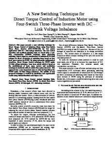
Stator flux vector λ s at instant t n has the angle θ (t n ) to the axes fixed to the stator (Fig.1). Desired flux magnitude Φ * is represented by a circle centered in the origin with a radius equal to the magnitude of flux reference
λ s = Ls I s + Lm I r
(3)
the stator flux vector increment, which will drive torque and flux errors (7) and (8) to zero:
λ r = Lr I r + Lm I s
(4)
(
(5)
Te =
3P λs × I s 2
ωm =
)
λ (t n +1 ) = Φ * . A new DTC algorithm is based on calculating
∆ λ = λ s (tn +1 ) − λ (tn ) .
(9)
q K2
ω
λs(tn+1)
(6)
P where λ s is the d – and q – axes stator flux complex vector
K1
∆λ
∆θ λ(tn) θ(tn)
with λ s = λ sd + jλ sq , λ r is the d – and q – axes rotor flux complex vector with λ r = λ rd + jλ rq , V s is the d – and q –
d
axes stator voltage complex vector with V s = Vsd + jVsq , I s is the d – and q – axes stator current complex vector with I s = I sd + jI sq , Rs and Rr are stator and rotor resistance, Ls and Lr are stator and rotor self – inductance, Lm is mutual inductance, Te is the electromagnetical torque, P is the pole – pair number, ω m and ω are the mechanical and electrical speed, respectively, and j is the imaginary unit. In the proposed model core losses and saturation are neglected.
Fig.1. Definition of stator flux vector increment
The desired stator flux vector increment (3) is defined by circle radius and the angle ∆ϑ shown on Fig. 1. So, it is necessary to calculate angle ∆ϑ which depends on desired changes in torque and flux (7) and (8), and than to calculate stator flux vector increment (9). Reference voltage than is:
B. Direct Torque Control Equations In DTC control schemes two discrete equations are given [114]: ∆T = T * − T (tn ) ,
(7) Vs =
*
where t n is the beginning of an arbitrary ∆t period, T is the reference or command value of torque, and ∆T is desired change in torque, and ∆Φ = Φ* − Φ (tn ) ,
∆λ + Rs I s . ∆t
(10)
It can be seen on Fig. 1 that by increasing the reference flux magnitude, Φ * the circle radius will be increased (and vice versa), and by increasing the reference torque T * on the
(8)
same flux level ( Φ * = λ (t n +1 ) = λ (t n ) ) the angle ∆ϑ will
where Φ * is the command value of stator flux magnitude, and ∆Φ is desired change in stator flux magnitude.
be increased (and vice versa).
966
Expressions (13) and (17) have to be substituted in (12), so the change of stator current will be:
The equation for developed torque of induction machine (5) can be linearized over the sampling period ∆t as:
(
)
(
3 3 P λ s × ∆ I s + P ∆λ s × I s 2 2
∆T =
)
(11)
∆I s =
where ∆T is the change in torque, and ∆ I s and ∆λ s are the changes in stator current and stator flux. By using an equivalent circuit of the inverter – driven induction machine in the stationary reference frame (Fig. 2), the change in stator current vector ∆ I s is given by [8]:
− ω e ∆t
(1 − σ )Trω s Lr
(
Ls 1 + σ 2Tr2ω s2
(
)
)
(18)
λs
It can be seen from Fig. 1 and equation (9) that:
[
]
λ s × ∆λ = λ s × λ s (tn +1 ) − λ s (tn ) =
*
V −E ∆t , σLs
∆I s =
(1 − σ )Lr λ − ∆λ s − j ω e ∆t s σLs σLs 1 + σ 2Tr2ω s2
(19)
= λ s (tn ) ⋅ λ s (tn +1 ) sin ∆ϑ
(12)
*
where V = V s − R s I s , σ = 1 − L2m Ls Lr is the leakage coefficient and
(
E = jω e λ s − σ L s I s
)
2
∆ λ s × j λ = λ s (tn ) ⋅ λ s (tn +1 ) cos ∆ϑ − λ s (tn ) , (20)
so the change in torque can be written by substituting (17) and (18) in (11) and using (19-20) as:
(13)
is the back emf, which is assumed to be sinusoidal with dominant frequency ω e .
∆T =
σLs
Rs
E
V*
3P (1 − σ ) λ s (tn )
(
2σLs 1 + ω s2σ 2Tr2
)[ λ (t
n +1
) sin ∆ϑ −
(21)
− λ s (tn ) ∆tω e + σTrω s ∆Φ]
~
For small values of angle ∆ϑ sine and cosine are:
Fig. 2. Equivalent circuit of inverter-driven induction machine
Rotor flux vector and rotor current vector can be rewritten in meaning of stator quantities by using (3) and (4) as:
(
)
(14)
1 λ s − Ls I s . Lm
(15)
L λ r = r λ s − σLs I s Lm Ir =
(
)
∆ϑ =
+
(
)
Is =
(
(
) + j(1 − σ )T ω )
Ls 1 + σ 2Tr2ω s2
r
s
cos ϑ = 1 ,
(23)
(
2σLs 1 + ω s2σ 2Tr2
)
3P(1 − σ ) λ s (tn ) ⋅ λ (tn +1 )
λ s (tn ) λ (tn +1 )
∆tω e −
∆ΦσTrω s
∆T +
(24)
λ (tn +1 )
(16) It can be seen from Eq. 24 than if there is no change in reference torque ( ∆T = 0 ) and no change in reference flux
and equations (14-16) have to be substituted in (2), which gives the expression for stator current (17): 1 + σTr2ω s2
(22)
so the desired stator flux vector increment angle is:
Total differential of (14) is L ∆ λ r = r ∆λ s − σLs ∆ I s , Lm
sin ∆ϑ = ∆ϑ ,
λs ,
( ∆Φ = 0 or λ (t n +1 ) = λ (t n ) ) stator flux vector increment angle is ∆ϑ = ω e ∆t , which means that the stator flux continues to rotate by synchronous speed. If there is no change in flux ( ∆Φ = 0 ), and the torque has to be increased, it can be seen from Eq. (24) that the stator flux vector increment angle ∆ϑ has to be increased (and vice versa). If there is a change both in stator flux magnitude and torque,
(17)
where ω s = ω e − ω is the slip frequency, and Tr = L r / R r is the rotor time constant.
967
stator flux vector increment angle ∆ϑ can be increased or decreased depending on torque and flux errors (7) and (8). In Fig. 3, the Eq. 21 is illustrated for the values of the angle − pi / 2 ≤ ∆ϑ ≤ pi / 2 for three levels of stator flux. It is assumed that there is unlimited voltage available, and it can be seen that there is possible to get larger torque with larger flux level.
Vd* =
Vq* =
[∆Φλ (t ) − λ (t
1 ∆t ⋅ λ (tn )
d
n
n +1
[∆Φλ (t ) + λ (t
1 ∆t ⋅ λ (t n )
q
n
n +1
) λq (tn )∆ϑ ]
(27)
) λd (t n )∆ϑ ]
(28)
The stator voltage vector reference than is:
(
)
V s = Vd* + jVq* + Rs I s (tn )
V.
(29)
TRANSIENT CONDITIONS
In transient conditions, when the torque and flux errors (7) and (8) are too large (particularly in field weaking region), the reference voltage (29) will be larger than the available inverter voltage. In that case, the angle ∆ϑ (24) has to be limited, so the reference voltage is lower or equal to the maximum inverter voltage:
Fig. 3 Plot of Eq. (20) for
IV.
V s ≤ U MAX ,
− pi / 2 ≤ ∆ϑ ≤ pi / 2
where U MAX is the maximum available inverter voltage. Neglecting stator IR voltage drop, and substituting (27-28) into (30) maximum angle rotation ∆ϑ allowed is:
REFERENCE VOLTAGE GENERATION
When the desired flux angle movement is determined, the flux projections in stationary dq reference frame from Fig.4 are: ∆λd = λ (tn +1 ) cos(ϑ (tn ) + ∆ϑ ) − λ (tn ) cosϑ (tn )
(25)
∆λq = λ (tn +1 ) sin (ϑ (tn ) + ∆ϑ ) − λ (tn ) sin ϑ (tn )
(26)
∆ϑ ≤ ±
VI.
.
(31)
REALIZATION OF PROPOSED ALGORITHM
1. Determine the state vector x(ω e , ω s , λ (t n ), λ (t n +1 ) ) ,
∆λ
and calculate torque and flux increments, ∆Te and ∆Φ (Eq. 7 and 8) from the estimated values; 2. Calculate the angle of stator flux adjacent ∆ϑ = f (∆Te , ∆Φ, x ) which defines the position of the
∆θ λ(tn) ∆λd
λ (tn +1 )
Implementation of the proposed algorithm is embodied in the following steps:
λ(tn+1)
θ(tn)
2 (∆t )2 − (∆Φ )2 U MAX
In this regime direct flux control is enabled, and torque is driven to its reference with the maximum increment possible.
q
∆λq
(30)
new stator flux vector λ (t n +1 ) to respect to λ (t n ) (Eq. 24); 3. Limit the angle ∆ϑ if necessary (Eq. 31);
d
Fig. 4. Projections of stator flux increment vector
4. Calculate the stator flux vector increment ∆λ (Eq. 25 and 26); 5. Calculate the stator reference voltage (Eq. 27-29).
Assuming (22-23) and the fact that the stator flux vector components λ d (t n ) and λ q (t n ) are known, reference voltage components are:
968
VII. SIMULATION RESULTS
VIII.
Results of computer simulation of induction motor controlled through the proposed algorithm are shown on Fig. 5 - 7. Model is based on Eq (1-6) in State – Space domain without neglecting the saturation, which is modeled by magnetization characteristic. Motor data are given in Appendix. Reference value of torque is 1Nm , and motor flux is weakened to 0.8 and 0.6 of nominal value. It can be seen from Fig. 4 that de-coupled control of torque and flux is achieved with minimum torque and flux ripple, and the initial error is minimized in dead-beat manner.
EXPERIMENTAL RESULTS
The experimental set up consisted of a three – phase induction motor, transistor inverter and dSpace 1102 digital controller. Inverter is driven by Space Vector Modulation technique with constant 3.5 kHz switching frequency. Two phase currents were measured and no shaft sensor was used for speed and position feedback. The results were captured using dSpace software. Extensive tests were conducted to verify the proposed algorithm. Fig. 8. shows the motor torque, and Fig. 9 shows stator flux magnitude. It can be seen that the Dead – Beat control of torque and flux is achieved, as expected.
Fig. 8. Motor torque – experimental results Fig. 5. Motor torque
Fig. 9 Stator flux magnitude – experimental results
Fig. 10. shows the angle of stator flux vector angular advancement. It can be seen that if the stator flux magnitude is decreased, the angle ∆ϑ is raised to achieve demanded torque according to Eq. (24).
Fig. 6. Stator flux magnitude
Motor currents are given on Fig. 7. It can be seen that the currents are changing their magnitude, frequency and phase angle due to changes in torque and flux reference.
Fig. 10. The angle of stator flux vector angular advancement
Experimental results show that the proposed algorithm has the same or even the better performance than the other DTC solutions presented in [1-14]. Fig. 7. Phase currents
969
IX. CONCLUSION
[3]
This paper presents a novel direct torque and flux control algorithm. This algorithm gives a unique solution for the voltage reference, which will drive torque and flux errors down to zero, by controlling both the radial and tangential component of stator flux vector increment. Proposed algorithm enables sensorless deadbeat control of torque and flux with constant switching frequency. Algorithm has no trigonometric functions and coordinate transformations compared to other solutions, and is easily implemented on most recent digital controlled drives.
[4] [5]
[6]
[7]
APPENDIX The rated values and parameters for the machine used in the simulation study and the experimental work are:
[8]
Rated output power 0.75kW Rated voltage 380V Y Rated frequency 50Hz Pole-pair number 2 Rated speed 1410rpm Power factor 0.71
[9]
Stator resistance 10.4Ω Rotor resistance 11.6Ω Stator Leakage Inductance Rotor Leakage Inductance Mutual Inductance
[10] [11] [12]
22mH 22mH 0.557H
[13]
REFERENCES [1] [2]
[14]
Peter Vas: Sensorless Vector and Direct Torque Control, Oxford University Press, London, 1998. Takahashi Isao, Noguchi Toshihiko: “A New Quick-Response and High-Efficiency Control Strategy of an Induction Mоtor” IEEE Transactions on Industry Applications, Vol. IA-22, No.5, Sept/Oct 1986.
970
M. Depenbrock: ”Direct Self-Control (DSC) of Inverter-Fed Induction Machine”, IEEE Transactions on Power Electronics, Vol.3, No.4, Oct. 1988 G. Buja, D. Casadei, G. Serra: “DTC – Based Strategies for Induction Motor Drives, IEEE-IAS Annual Meeting 2002, pp 1506-1516. T. Noguchi, M. Yamamoto, S. Kondo, I. Takahashi: ”Enlarging Switching Frequency in Direct Torque – Controlled Inverter by Means of Dithering, IEEE Transactions on Industry Applications, Vol. 35, No. 6, Nov/Dec. 1999. Jun – Koo Kang, Seung – Ki Sul: “New Direct Torque Control of Induction Motor for Minimum Torque Ripple and Constant Switching Frequency”, IEEE Transactions on Industry Applications, Vol. 35, No5, Sept/Oct 1999. Тhomas G. Habetler, Deepakraj M. Divan: ”Control Strategies for Direct Torque Control Using Discrete Pulse Modulation”, IEEE Transactions on Industry Applications, Vol. 27, No. 5, Sept/Oct 1991 Thomas G. Habetler, Francesco Profumo, Michele Pastorelli, Leon M. Tolbert: “Direct Torque Control of Induction Machines Using Space Vector Modulation”, IEEE Transactions on Industry Applications, vol. 28, No.5, Sept/Oct 1992. Giovani Griva, Thomas G. Habetler: ”Performance Evaluation of a Direct Torque Controlled Drive in the Continuous PWM-Square Wave Transition Region”, IEEE Transactions on Power Electronics, Vol. 10, No.4, July 1995. Barbara H. Kenny, Robert D. Lorenz: “Stator and Rotor Flux Based Deadbeat Direct Torque Control of Induction Machines”, IEEE Transactions on Industrial electronics, Vol. 30, No. 4 2001. Thomas G. Habetler, Francesco Profumo, Michele Pastorelli: ”Direct Torque control of Induction Machines Over a Wide Speed Range”, IEEE-IAS Annual Meeting, Conf. Rec. 1992, pp.600-606 Kevin D. Hurst, Thomas G. Habetler: ”A Simple, Tacho-Less, I. M. Drive with Direct Torque Control Down to Zero Speed”, IEEE Transactions on Industry Applications, 1995, Vol. 5, No. 5, pp.563568. D. Casadei, G. Serra, A. Tani: “Analytical Investigation of Torque and Flux Ripple in DTC Schemes for Induction Motors”, IEEE-IAS Annual Meeting 2002. C. Lascu, A. Trzynadlowski: “Combining the Principles of Sliding Mode, Direct Torque Control, and Space Vector Modulation in a High – Performance Sensorless AC Drive”, IEEE-IAS Annual Meeting 2002.