International Journal of Power Electronics and Drive System (IJPEDS) Vol. 7, No. 4, December 2016, pp. 1049~1060 ISSN: 2088-8694, DOI: 10.11591/ijpeds.v7i4.pp1049-1060
1049
Improved Stator Flux Estimation for Direct Torque Control of Induction Motor Drives Yahya Ahmed Alamri1, Nik Rumzi Nik Idris2, Ibrahim Mohd. Alsofyani3, Tole Sutikno4 1,2,3
UTM-PROTON Future Drive Laboratory, Power Electronics and Drives Research Group, Faculty of Electrical Engineering, Universiti Teknologi Malaysia, 81310 Skudai, Johor, Malaysia 4 Department of Electrical Engineering, Universitas Ahmad Dahlan, Janturan, Yogyakarta 55164, Indonesia
Article Info
ABSTRACT
Article history:
Stator flux estimation using voltage model is basically the integration of the induced stator back electromotive force (emf) signal. In practical implementation the pure integration is replaced by a low pass filter to avoid the DC drift and saturation problems at the integrator output because of the initial condition error and the inevitable DC components in the back emf signal. However, the low pass filter introduces errors in the estimated stator flux which are significant at frequencies near or lower than the cutoff frequency. Also the DC components in the back emf signal are amplified at the low pass filter output by a factor equals to . Therefore, different integration algorithms have been proposed to improve the stator flux estimation at steady state and transient conditions. In this paper a new algorithm for stator flux estimation is proposed for direct torque control (DTC) of induction motor drives. The proposed algorithm is composed of a second order high pass filter and an integrator which can effectively eliminates the effect of the error initial condition and the DC components. The amplitude and phase errors compensation algorithm is selected such that the steady state frequency response amplitude and phase angle are equivalent to that of the pure integrator and the multiplication and division by stator frequency are avoided. Also the cutoff frequency selection is improved; even small value can filter out the DC components in the back emf signal. The simulation results show the improved performance of the induction motor direct torque control drive with the proposed stator flux estimation algorithm. The simulation results are verified by the experimental results.
Received May 20, 2016 Revised Oct 25, 2016 Accepted Nov 6, 2016 Keyword: Direct torque control Induction motor Low speed operation Stator flux estimation
Copyright © 2016 Institute of Advanced Engineering and Science. All rights reserved.
Corresponding Author: Yahya Ahmed Alamri, Faculty of Electrical Engineering, Universiti Teknologi Malaysia, 81310, Skudai, Johor, Malaysia. Email:
[email protected]
1.
INTRODUCTION Recently, direct torque control (DTC) has becoming a promising alternative solution to high performance vector control technique for induction motor drives [1], [2]. Compared to the vector control, DTC has a very simple structure, does not require current regulators, and in principle does not require a speed sensor to operate. The performance of DTC drive very much depends on the accuracy of the estimated electromagnetic torque and stator flux linkage based on the terminal variables of the machine, such as the stator currents and voltages. In general, the flux linkage vector can be estimated either based on the voltage model, or the current model equations. The advantages of the voltage model method over the current model method are its simple implementation that does not require rotor speed information; the only parameter required is the stator winding resistance. However, it turns out that the estimation of the stator flux linkage using voltage model normally has problems at low speed operations. Journal homepage: http://iaesjournal.com/online/index.php/IJPEDS
IJPEDS
ISSN: 2088-8694
1050
In the literature, two general approaches are followed to overcome the voltage-model-based estimator shortcomings. The first approach is based on the compensation of the errors that are present in the measured and reconstructed stator current and voltage signals which requires an identification process to obtain accurate values of the stator resistance and the voltage source inverter (VSI) model parameters [3]-[6]. However, most of these parameters varies with the operating conditions which increase the complexity of the identification process. The second approach is based on improving the integration algorithm for stability and accuracy of the voltage-model-based estimation method [7]-[17]. Basically the stator flux is obtained by an open loop integration of the induced stator back electromotive force (emf). In practice the pure integration cannot be easily implemented because of the initial condition problem and the inevitable DC offset in the back emf signal. Thus, normally low pass (LP) filter replaces the pure integration to eliminates the initial condition problem and prevent the saturation of the estimated stator flux. However, LP filter introduces magnitude and phase errors in the estimated stator flux which increase at frequencies near or lower than the cutoff frequency. These errors will degrade the performance of the drive system; therefore, different compensation algorithms have been proposed to compensate for these errors [8]-[13]. In [8] three integration algorithms are presented which are composed of a LP filter followed by a feedback loop to compensate for the LP filter errors. Amplitude limiters are added in the feedback loop to prevent the integration from saturation. The third integration algorithm used an adaptive method to maintain the orthogonality between the back emf and the stator flux vectors. In [9] a first order LP filter with a programmable cutoff frequency is used to solve the DC drift, with amplitude and phase angle errors compensation algorithm. However, multiplication and division by the stator frequency ( ) are involved in the amplitude and phase errors calculations. Also in [10] a LP filter with a fixed cutoff frequency is proposed to improve the DTC drive performance and the compensation algorithm is activated only at the steady state condition. Further improvements on this type of estimator have been introduced in several studies [11]-[13]. The compensation algorithm is simplified where the multiplication and division by are avoided. And the stator frequency is estimated based on a phase locked loop (PLL) method instead of the induction motor equation based method [12]. In [11]-[13] the speed reversal problems are avoided by carrying out the compensation before the LP filter. Also in [13], the estimator response time is reduced by increasing the cutoff frequency value. To estimate the flux in a wide speed range the LP filter cutoff frequency has to be very small. That causes a slow decay of the DC components and the DC offset appears at the estimated signal. In [14] a programmable cascade LP filter is proposed to solve the DC offset at low frequencies, where, a cascade LP filters with large cutoff frequencies replace the single stage LP filter with a small cutoff frequency. The time constant is selected in such a way that the phase angle of the cascade LP filter is equivalent to that of the pure integration and the output signal is multiplied by a gain compensator. Also in [15] two cascade LP filters with a cutoff frequency equals to the stator frequency is introduced, which have a phase angle equivalent to the pure integration phase angle. However, in the programmable cascade LP filter-based estimator, the multiplication by is required for the amplitude error compensator, which causes the estimator to behave as a zero gain at zero stator frequency [13]. Also the multiplication or division by is required in the cutoff frequency calculation which is a problematic at the motor start up and zero speed. In [16], and [17] an integration algorithms composed of a high order LP filter followed by a first order high pass (HP) filter with a cutoff frequency equals to the stator frequency are introduced which reduce the estimator sensitivity to the DC components compared to the previous estimators. This is because of the differential part included in the HP filter that makes the DC gain of the estimator equals to zero. However, in this solution, the multiplication by is required for the amplitude error compensation because of the cascade LP filters present in the integration algorithm. In this paper, a new algorithm for stator flux estimation is proposed to improve the performance of the DTC drive. The proposed algorithm is composed of a second order HP filter and an integrator. Therefore, the proposed algorithm has the zero DC gain advantages and the problems associated with the cascade LP filter are avoided. The structure of this paper is organized as follows. In the next section the proposed integration algorithm with its amplitude and phase errors compensation algorithm are presented. Then in section 3 the simulation results of the DTC drive with the proposed integration algorithm are presented followed by the experimental results. In this paper the results of the proposed estimator algorithm are compared with the results of the compensated LP filter algorithm that has been proposed in [11], [13]. Finally, the conclusion is given in section 4.
2.
PROPOSED INTEGRATION ALGORITHM The following equations describe the IM dynamic model:
Improved Stator Flux Estimation for Direct Torque Control of Induction Motor Drives (Yahya Ahmed A.)
1051
ISSN: 2088-8694 (1)
(2) (3) (4) Where, the variables and parameters are defined as Stator voltage, stator current, and rotor current space vectors. Stator and rotor flux space vectors Rotor speed Stator and rotor resistances Stator and rotor inductance Mutual inductance The variables are space vectors in stationary reference frame and can be represented in d-q components as follow [
]
[
]
[
]
[
]
[
]
The stator flux estimation in this paper is based on the so called voltage model which is derived from (1). Theoretically, the stator flux can be obtained by integrating the back EMF as follows: ∫(
)
(5)
The frequency response of the pure integrator based estimator of (5) can be written as: (6) where is the back EMF and is the operating frequency, i.e. the synchronous frequency. The main advantage of using the voltage model based estimator over other methods, such as current model, is its simplicity and no speed information requirement. However, the stator flux estimation based on voltage model, as discussed earlier, has stability problem in the practical implementation. Therefore, in practice, instead of an integrator, a LP filter, as given by (7), is used. (7) In (7), , is the cufoff frequency of the LP filter, and is the estimated stator flux linkage vector. For DTC application, errors in the magnitude and phase of the estimated flux can cause the incorrect selection of the voltage vectors, particularly at the boundary between 2 sectors. For flux estimation based on a LP filter, the operating frequency has to be set a decade higher than cutoff frequency in order to minimize the magnitude and phase errors, otherwise compensations to the magnitude and phase of the estimated value has to the applied. An example of a compensation that can be used for the LP filter based estimator is shown in Figure 1 [11], [13]. Since the DC gain of the LP filter based estimator is given by ⁄ , setting the cut-off frequency too low will reduce the effectiveness of the filter to remove the DC offset present in the back EMF. No matter what value the cut-off frequency is set, the DC offset will still be present in the estimated flux. On the other hand, if the cut-off frequency is set too high, the capability of the drive to operate at low speed region will be reduced. In DTC drive of IM, the problem of the DC offset does not appear in the estimated flux because the stator flux amplitude is controlled. However, the estimated flux components waveforms and phase angle are distorted.
IJPEDS Vol. 7, No. 4, December 2016 : 1049–1060
IJPEDS
ISSN: 2088-8694 sd
1
+
sd
e|
s +k |
+
1052
K sgn ( e)
K sgn ( e)
sq
-
1
+
s +k |
sq e|
Figure 1. The Compensated LP Filter Integration Algorithm [11], [13]
Bode Diagram 200
Magnitude (dB)
Pure Integration Low Pass Filter Proposed Integration
100 0 -100 -200
Phase (deg)
90 45 0 -45 -90 -6
-4
10
-2
10
10
0
10
Frequency (rad/s)
2
10
4
10
6
10
able
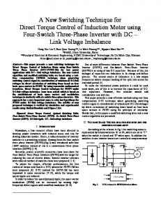
Figure 2. Frequency Response of an Integrator, LP Filter and the Proposed Filter at a Cut off Frequency of 5 rad/s
Consequently, the stator flux sector is not correctly estimated and the wrong stator voltage vectors are Therefore, to improve the performance of the DTC drive the DC offset has to be completely removed regardless of operating frequency. The LP filter based estimator given by (7) can be considered as a combination of a first order HP filter and a pure integration, which can be written as (8). (8) In order to increase the DC offset rejection, in this paper, we propose to replace the first order HP filter with a second order HP filter, as given by (9).
(
)
(
)
(9)
Figure 2 shows the frequency response of an integrator, a LP filter based estimator and the proposed estimator (equation (9)). In this figure, the cutoff frequency both for the LP and proposed filters is set to 5 rad/s. It can be seen from the figure that proposed filter is more capable of eliminating the DC offset compared to the other methods, however it also introduce the largest phase error if the operating frequency is close to the cutoff frequency. If the operating frequency is much higher than the cutoff, the proposed filter gives the best performance in terms of DC offset rejection. Using the proposed filter, it is therefore necessary to compensate the estimated flux in order to minimize the error. The error in the estimated stator flux is compensated in such a way that the frequency response of the proposed integration algorithm is equivalent to that of the pure integration. The frequency response function of (9) can be written as Improved Stator Flux Estimation for Direct Torque Control of Induction Motor Drives (Yahya Ahmed A.)
1053
ISSN: 2088-8694
(
(10)
)
Taking the ratio of the estimated stator flux between the pure integrator (6) and the proposed filter (10) the following equation is obtained. (
)
(11)
Then, the compensated flux equation for the proposed stator flux estimator is given by *(
)
+
(12)
When the cutoff frequency is selected as a function of the stator frequency, simplified as [(
)
(
)]
[
(
|
)]
|, (12) can be
(13)
The stator flux estimation using the proposed filter including the compensation in (13) can be implemented as shown in Figure 3. To improve the estimation in the reverse speed operation, part of the compensation algorithm is performed before the integration algorithm.
sd
sq
+
s
+
( s +k |
e |)
2
+
K sgn ( e)
K sgn ( e)
K sgn ( e)
K sgn ( e)
-
s
+
( s +k |
sd
+
e |)
2
sq
+
Figure 3. The Proposed Stator Flux Integration Algorithm
3. SIMULATION AND EXPERIMENTAL RESULTS 3.1. Simulation Results In order to study the effectiveness of the proposed method, the DTC induction motor drive system shown in Figure 4 is simulated using Matlab/SIMULINK simulation package. For the purpose of comparison, the stator flux is estimated using the LP filter and also the proposed estimator (both with compensations). The estimated electromagnetic is calculated using the estimated flux using (14) (
)
(14)
In order to perform the compensation, the operating frequency (the stator flux frequency) is calculated by taking the average value of (15)
IJPEDS Vol. 7, No. 4, December 2016 : 1049–1060
IJPEDS
ISSN: 2088-8694
|
1054 (15)
|
The values of the IM parameters for the simulation are given in Table 1. The cutoff frequency is a programmable value which is a gain multiplied by the absolute value of the estimated stator flux frequency. Therefore, the compensation algorithm as presented in section 2 is free of multiplication or division by the stator flux frequency. To evaluate the performance of both estimators in performing the estimation with the present of DC offset, a DC offset of 1 volt is introduced in the back EMF signal.
Vdc
𝑻𝒓
𝒇
-
,𝒓 𝒇
Sa
𝒅𝑻
+
Switching Sb Table
𝒅
+
Sc
Voltage Source Inverter (VSI)
-
𝝆
𝑻
Stator flux and electromagnetic Torque estimator IM
Figure 4. Induction Motor Direct Torque Control Drive Scheme.
For the LP filter estimator, the present of DC components in the back emf signals introduces an error in the estimated stator flux phase angle as shown in Figure 5(c). The flux hysteresis and torque hysteresis controllers are operated based on the incorrect stator flux and torque information thus selecting the incorrect voltage vectors that are used to control the flux and torque. The actual torque waveform is shown in Figure 5(f) indicated the presence of the oscillation due to this error. The incorrect voltage vector selection also can be seen from the distorted stator flux phase angle and magnitude. Subsequently, the oscillations are reflected in the stator and rotor frequencies as shown in Figure 5(d) and (e) respectively. The simulation results in Figure 6 on the other hand, shows the results obtained based on the proposed stator flux estimator. The simulation results show that, the DC offset at the output of the integration is totally eliminated. Consequently, the overall performance of the DTC drive is improved and the rotor speed is ripple free. 3.2. Experimental Results To verify the simulation results presented in the previous section, experimental test has been carried out using the DTC IM drive setup shown in Figure 7. The performance of the proposed integration algorithm for stator flux estimation is tested in various operation condition by the experimental data taken from the drive, which are the stator currents and voltages. Firstly, the performance of proposed integration algorithm is compared with that of the compensated LP filter at 20 rad/sec rotor speed with the present of 1 volt DC component in the back emf signal. For the compensated LP filter results shown in Figure 9 the DC offset appears in the d-q waveforms of the estimated stator flux and consequently a ripple in the estimated stator flux frequency as shown in Figure 8 (d). Whereas the proposed integration algorithm results are shown in Figure 9. There is no DC offset and the frequency oscillation is very much improved. Next, the proposed estimator is evaluated in the reverse and low speed operation. Figure 10 shows the validity of the compensation algorithm in the reverse speed condition where the motor speed is changed from 20 rad/sec to -20 rad/sec. Accurate and stable estimation of the amplitude and phase angle is also achieved at 5 rad/sec rotor speed as shown in Figure 11.
Improved Stator Flux Estimation for Direct Torque Control of Induction Motor Drives (Yahya Ahmed A.)
1055
ISSN: 2088-8694
1.5 d-axis q-axis 1
[Vs]
1
Stator flux amplitude
Stator flux
[Vs]
0.5
0
-0.5
-1
-1.5
0.8
0.6
0.4
0.2
0
0.1
0.2
0.3
0.4
0.5 Time [s]
0.6
0.7
0.8
0.9
0
1
0
0.1
0.2
0.3
0.4
(a)
0.5 Time [s]
0.6
0.7
0.8
0.9
1
0.9
1
(b)
4
Stator flux phase angle [rad]
3 2 1 0 -1 -2 -3 -4
0
0.1
0.2
0.3
0.4
0.5 Time [s]
0.6
0.7
0.8
0.9
1
(c) 21
70
20.8
60
Rotor speed [rad/sec]
Synchronous speed [rad/sec]
20.6
50 40 30 20 10
20.4 20.2 20 19.8 19.6 19.4 19.2
0
19
-10
0
0.1
0.2
0.3
0.4
0.5 Time [s]
0.6
0.7
0.8
0.9
0
0.1
0.2
0.3
0.4
0.5 Time [s]
1
0.6
0.7
0.8
(e)
(d) 12 10 8
Torque (N.m)
6 4 2 0 -2 -4 0
0.1
0.2
0.3
0.4
0.5 Time(sec)
0.6
0.7
0.8
0.9
1
(f) Figure 5. Simulation results for DTC with the compensated LP filter, k=0.2, and vDC = 1volts. (a) d-q stator flux components (b) stator flux amplitude (c) stator flux phase angle (d) stator flux frequency (e) rotor speed (f) electromagnetic torque IJPEDS Vol. 7, No. 4, December 2016 : 1049–1060
IJPEDS
ISSN: 2088-8694
1056
1.5 d axis q axis 1
Stator flux amplitude [Vs]
1
Stator flux [Vs]
0.5
0
-0.5
0.6
0.4
0.2
-1
-1.5
0.8
0
0
0.1
0.2
0.3
0.4
0.5 Time [s]
0.6
0.7
0.8
0.9
1
0
0.1
0.2
0.3
0.4
0.5 Time [s]
0.6
0.7
0.8
0.9
1
0.9
1
(b)
(a) 4
Stator flux phase angle [rad]
3 2 1 0 -1 -2 -3 -4
0
0.1
0.2
0.3
0.4
0.5 Time [s]
0.6
0.7
0.8
0.9
1
(c) 80
21 20.8
70
Rotor speed [rad/sec]
Synchronous speed [rad/sec]
20.6 60 50 40 30
20.4 20.2 20 19.8 19.6
20 19.4 10 0
19.2
0
0.1
0.2
0.3
0.4
0.5 Time [s]
0.6
0.7
0.8
0.9
19
1
0
0.1
0.2
0.3
(d)
0.4
0.5 Time [s]
0.6
0.7
0.8
(e)
12 10 8
Torque (N.m)
6 4 2 0 -2 -4 0
0.1
0.2
0.3
0.4
0.5 Time (sec)
0.6
0.7
0.8
0.9
1
(f) Figure 6. Simulation results for DTC with the proposed integration algorithm, k=0.2 and vDC =1volts. (a) d-q stator flux components (b) stator flux amplitude (c) stator flux phase angle (d) stator flux frequency (e) rotor speed (f) electromagnetic torque
Improved Stator Flux Estimation for Direct Torque Control of Induction Motor Drives (Yahya Ahmed A.)
1057
ISSN: 2088-8694 Vdc
Reference values (Speed and flux)
|d |
dSPACE 1104 (speed, Torque, and flux observers and controllers)
dTe
FPGA
sector
(DTC Look Up Table)
Sa,b,c
Gate Driver
Sa,b,c _
Sa,b,c
Voltage Source Inverter (VSI)
isa, isb Current sensors
Experimental Results
Proposed Integration Algorithm.
IM
Figure 7. Block diagram of the experiment set-up
1.5
1.4 d-axis q-axis
1.2
Stator flux amplitude [Vs]
1
Stator flux
[Vs]
0.5
0
-0.5
-1
-1.5
1
0.8
0.6
0.4
0.2
0
0.5
1
1.5 Time [s]
2
2.5
0
3
0
0.5
(a)
1
1.5 Time [s]
2
2.5
3
(b)
4
Stator flux phase angle [rad]
3 2 1 0 -1 -2 -3 -4
0
0.5
1
1.5 Time [s]
2
2.5
3
2
2.5
3
(c) 60
Synchronous speed [rad/sec]
50
40
30
20
10
0
0
0.5
1
1.5 Time [s]
(d) Figure 8. Experimental Results for the Compensated LP filter, k=0.2 and vDC=1volts. (a) d-q Stator Flux Components (b) Stator Flux Amplitude (c) Stator Flux Phase Angle (d) Stator Flux Frequency
IJPEDS Vol. 7, No. 4, December 2016 : 1049–1060
IJPEDS
ISSN: 2088-8694
1058
1.4
1.5 d-axis q-axis
1.2
Stator flux amplitude [Vs]
1
Stator flux [Vs]
0.5
0
-0.5
1
0.8
0.6
0.4
0.2
-1
0
-1.5
0
0.5
1
1.5 Time [s]
2
2.5
0
0.5
1
3
1.5 Time [s]
2
2.5
3
(b)
(a) 4 3
Stator flux phase angle [rad]
2 1 0 -1 -2 -3 -4
0
0.5
1
1.5 Time [s]
2
2.5
3
(c) 60
Synchronous speed [rad/sec]
50
40
30
20
10
0
0
0.5
1
1.5 Time [s]
2
2.5
3
(d) Figure 9. Experimental Results for the Proposed Integration Algorithm, k=0.2 and vDC=1volts. (a) d-q Stator Flux Components (b) Stator Flux Amplitude (c) Stator Flux Phase Angle (d) Stator Flux Frequency
1.4
1.5 d-axis q-axis
1.2
Stator flux amplitude [Vs]
1
Stator flux [Vs]
0.5
0
-0.5
1
0.8
0.6
0.4
0.2
-1
0
-1.5
0
1
2
3 Time [s]
4
5
0
1
6
2
3 Time [s]
4
5
6
(b)
(a) 60
Synchronous speed [rad/sec]
40
20
0
-20
-40
-60
0
1
2
3 Time [s]
4
5
6
(c) Figure 10. Experimental Results for the Proposed Integration Algorithm at reverse speed, k=0.2. (a) d-q Stator Flux Components (b) Stator Flux Amplitude (c) Stator Flux Frequency Improved Stator Flux Estimation for Direct Torque Control of Induction Motor Drives (Yahya Ahmed A.)
1059
ISSN: 2088-8694
1.5 d-axis q-axis 1
Stator flux amplitude [Vs]
1
Stator flux
[Vs]
0.5
0
-0.5
-1
-1.5
0.8
0.6
0.4
0.2
2
2.5
3
3.5 Time [s]
4
4.5
0
5
2
2.5
3
(a)
3.5 Time [s]
4
4.5
5
(b)
4
Stator flux phase angle [rad]
3 2 1 0 -1 -2 -3 -4
2
2.5
3
3.5 Time [s]
4
4.5
5
(c) Figure 11. Experimental Results for The Proposed Integration Algorithm at Low Frequency, 5 rad/sec Rotor Speed, k=0.2 (a) d-q Stator Flux Components (b) Stator Flux Amplitude (c) Stator Flux Phase Angle
Table 1. Induction Motor Parameters Rs (Ω) 3
Rr(Ω) 4.1
Ls(H) 0.3419
Lr(H) 0.3513
Lm(H) 0.324
JL(Kg. m2) 0.00952
P 4
4.
CONCLUSION A new algorithm for stator flux estimation is proposed for the DTC drive of IM, which consists of a cascaded second order HP filter and pure integration. A simple algorithm for the amplitude and phase angle errors compensation is derived based on the steady state condition analysis. The advantages of the proposed integration algorithm are it is simplicity, the multiplication and division by stator frequency are avoided, and completely rejects the DC offset present in the back EMF. The simulation and the experimental results show improvement in the stator flux estimation accuracy and the DTC drive overall performance.
ACKNOWLEDGEMENTS The authors would like to thank Universiti Teknologi Malaysia for the funding of this research (RMC Vot 12H30)
REFERENCES [1] [2] [3] [4] [5]
I. Takahashi and T. Noguchi, “A new quick-response and high-efficiency control strategy of an induction motor”, IEEE Trans. Ind. Applicat., vol. IA-22, pp. 820–827, Sept./Oct. 1986. P. Vas, Sensorless Vector and Direct Torque Control. London, U.K.: Oxford Univ. Press, 1998. J. Holtz and J. Quan, “Sensorless vector control of induction motors at very low speed using a nonlinear inverter model and parameter identification", IEEE Trans. Ind. Appl., vol. 38, no. 4, pp. 1087–1095, Jul./Aug. 2002. J. W. Choi, and S.K. Sul, “Inverter output voltage synthesis using novel dead time compensation", IEEE Trans. On Power Elect. Vol. 11, no. 2, Mar. 1996. G. Pellegrino, R.I. Bojoi, P. Guglielmi, and F. Cupertino, "Accurate inverter error compensation and related selfcommissioning scheme in sensorless induction motor drives", IEEE Trans. On Indus. Applications. Vol. 46, No. 5, Sep./Oct. 2010.
IJPEDS Vol. 7, No. 4, December 2016 : 1049–1060
IJPEDS [6] [7] [8] [9] [10] [11] [12] [13] [14] [15] [16] [17]
ISSN: 2088-8694
1060
Yongsoon Park; Seung-Ki Sul, "A Novel Method Utilizing Trapezoidal Voltage to Compensate for Inverter Nonlinearity", Power Electronics, IEEE Transactions on, vol.27, no.12, pp.4837,4846, Dec. 2012. K.D. Hurst, T.G. Habetler, G. Griva, and F. Profumo, “Zero-speed tacholess IM torque control: Simply a matter of stator voltage integration”, IEEE Trans. Ind. Applicat., vol. 34, pp. 790–795, July/Aug. 1998. J. Hu and B. Wu, “New integration algorithms for estimating motor flux over a wide speed range", IEEE Trans. Power Electron. vol. 13, no. 5, pp. 969–977, Sep. 1998. M.H. Shin, D.S. Hyun, S.B. Cho, and S.Y. Choe, “An improved stator flux estimation for speed sensorless stator flux orientation control of induction motors", IEEE Trans. Power Electron., vol. 15, pp. 312–318, Mar. 2000. N.R.N. Idris and A.H.M. Yatim, “An improved stator flux estimation in steady-state operation for direct torque control of induction machines", IEEE Trans. Ind. Appl., vol. 38, no. 1, pp. 110–116, Jan./Feb. 2002. M. Hinkkanen and J. Luomi, “Modified integrator for voltage model flux estimation of induction motors", IEEE Trans. Ind. Electron., vol. 50, no. 4, pp. 818–820, Aug. 2003. M. Comanescu and L. Xu, “An improved flux observer based on PLL frequency estimator for sensorless vector control of induction motors", IEEE Trans. Ind. Electron., vol. 53, no. 1, pp. 50–56, Feb. 2006. Stojic D., Milinkovic M., Veinovic S., Klasnic I., "Improved Stator Flux Estimator for Speed Sensorless Induction Motor Drives", Power Electronics, IEEE Transactions on, vol.30, no.4, pp.2363,2371, April 2015. B.K. Bose and N.R. Patel, “A programmable cascaded low-pass filter-based flux synthesis for a stator flux-oriented vector-controlled induction motor drive", IEEE Trans. Ind. Electron., vol. 44, no. 1, pp. 140–143, Feb. 1997. G. Tan, X. Wu, Z. Ye, Y. Han, and P. Guo, “Dual three-level double-fed induction motor control based on novel stator flux observer”, in Proc. Int.Conf. Elect. Control Eng., 2010, pp. 3668–3671. Y. Wang and Z. Deng, “An integration algorithm for stator flux estimation of a direct-torque-controlled electrical excitation flux switching generator", IEEE Trans. Energy Convers., vol. 27, no. 2, pp. 411–420, Jun. 2012. Y. Wang and Z. Deng, “Improved stator flux estimation method for direct torque linear control of parallel hybrid excitation switched-flux generator", IEEE Trans. Energy Convers., vol. 27, no. 3, pp. 747–756, Sep. 2012.
Improved Stator Flux Estimation for Direct Torque Control of Induction Motor Drives (Yahya Ahmed A.)