A Novel Droplet Routing Algorithm for Digital Microfluidic Biochips Pranab Roy
Hafizur Rahaman
Parthasarathi Dasgupta
School of VLSI Technology, Bengal Engineering and Science University, Shibpur, India Email:
[email protected]
School of VLSI Technology, Bengal Engineering and Science University, Shibpur, India Email:
[email protected]
Indian Institute of Management Calcutta, India Email:
[email protected]
ABSTRACT One of the recent areas of research interest is the use of microfluidics for building up biochips, the digital microfluidic biochips (DMFB). This paper deals with a challenging problem related to the design of DMFB. Specifically the design problem considered is related to high performance droplet routing, where each droplet has single source location and single target location. The objectives are (i) minimizing the number of electrodes used in the DMFB, and (ii) minimizing the total routing time of all the droplets or arrival time of a droplet that is the last to arrive at its target(latest arrival time). We propose a simple algorithm for concurrent path allocation to multiple droplets, based on the Soukup’s routing algorithm [22], together with the use of stalling, and possible detouring of droplets in cases of contentions. Selection of the droplets is based on their respective source to target Manhattan paths. The empirical results are quite encouraging.
Categories and Subject descriptors B.7.2 [Integrated Circuits]: Design Aids; G.2.2 [Graph Theory]:Path and circuit problems; I.2.8 [Problem Solving, Control Methods, and Search ]:Heuristic Methods ; J.3 [Life and Medical Sciences]: Biology and Genetics, Health;
General Terms: Algorithms, Design Additional Keywords and Phrases:
Microfluidics,
Biochips, Layout, Placement and Routing
1. INTRODUCTION Microfluidic chips or Micro-electromechanical systems (MEMS) consist of sub millimeter-scale components such as channel, valves, pumps, microliter of fluids and so on - on a small 2D array of electrodes. One of the most advanced technologies to build a biochip is based on microfluidics where micro or nano-liter droplets are controlled or manipulated to perform intended biochemical operations on a miniature lab, commonly known as a lab on a chip (LOC) [6]. The recent generation of digital microfluidic biochip (DMFB) has been proposed based on a recent technology breakthrough where the continuous liquid flow is sliced or digitized into droplets. Each droplets is manipulated independently by electric field. This architecture for microfluidic systems is attractive Permission to make digital or hard copies of all or part of this work for personal or classroom use is granted without fee provided that copies are not made or distributed for profit or commercial advantage and that copies bear this notice and the full citation on the first page. To copy otherwise, or republish, to post on servers or to redistribute to lists, requires prior specific permission and/or a fee.
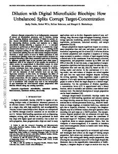
Due to (1) greater flexibility - analyte handling may be reconfigured simply by reprogramming instead of by changing the physical layout of the microfluidic components ,(2) high droplet speeds [3], (3) no dilution and cross contamination due to diffusion and shear flow and (4) the possibility of having massively parallel microfluidic circuits. Digital microfluidic biochips have a vast multitude of applications including clinical diagnosis, environmental studies, and military operations. Its functioning is based on the principle of electrowetting-on-dielectric (EWOD) [10]. As shown in Figure 1, a biochip consists of an array of electrodes guided by two parallel plates. The top plate is applied a ground voltage and the bottom plates are applied high voltages to ease the transportation of nanoliter or microliter droplets through the arrays. Each parallel plate electrode pair is treated as unit cell in the biochip, as shown in the Figure 2. The small fluidic droplets move from one unit cell to its neighboring unit cell by the application of proper voltage at the bottom plate. The applied voltages are changed according to the need for moving the droplets from one electrode to the other, and the process can be controlled by a processor of predefined clock frequency that determines the velocity of movement of the droplets [15]. Recently, [7] described a coplanar microfluidic device, which is an array without a top plate. Due to their digital nature, any operation on droplets can be accomplished with a set of library operations like VLSI standard library, controlling a droplet by applying a sequence of preprogrammed electric signals (Actuation sequences) [5]. Therefore, a hierarchical cell-based design methodology can be applied to a DMFB. Thus, a natural consequence of this is that large scale complex DMFB can be designed as done in VLSI, once strong CAD frameworks are ready. However, CAD research for DMFB design has started very recently. In [15], the first top down methodology for a DMFB is proposed, which mainly consists of architecture level synthesis and geometry-level synthesis. The geometry-level synthesis in DMFBs broadly involves module placement and droplet routing. During module placement, the location of each module is determined to minimize chip area or response time. In droplet routing, the path of each droplet transports it without any unexpected mixture under design requirements. As in the module placement, a cell can be used to transport different droplets during different time intervals (time-multiplexing), which increases the complexity of routing. The most critical goal of droplet routing is routability as in VLSI [20], while satisfying timing constraint and maximizing fault tolerance [6]. Synthesis procedure of digital microfluidic biochip involves optimization of certain cost functions under some resource constraints [15]. During placement of cells, area optimization as well as resource sharing is essential for easier subsequent phases. Typically, in droplet routing,
some of the parameters optimized are the throughput, time and resource utilization. The rest of the paper is organized in the following manner. Section 2 discusses the related works available in existing literature, and Section 3 summarizes the major contributions of our work. Section 4 discusses some preliminary concepts related to droplet routing. Section 5 introduces the problem formulation while Section 6 discusses the proposed methods and briefs the proposed Algorithm, along with an example of two pin net. Section 7 summarizes the empirical results, and Section 8 makes the concluding remarks.
2. RELATED WORKS Digital microfuidic biochip integration has been a major research area recently and designers attempt for optimization of the ever increasing complex design [11].
to other droplets). Then the droplets are arranged to route in parallel without considering blockage. Routing of the remaining droplets is considered in presence of blockage and a concession zone was introduced to ascertain feasibility of the routing. Finally a compaction based algorithm was run to optimize the solution. In [8], a network flow based algorithm was proposed for droplet routing. The proposed method was based on non-intersecting bounding box technique. The bounding box of each net was determined first. Then a non-intersecting set of bounding boxes were chosen to route first. The remaining nets were routed using min-cost max-flow algorithm. [1] proposed an A* search algorithm. The states of the source-target pairs at different times are differentiated using a graph representation. Then optimal path from source to target was chosen using the A* search algorithm. Pin constraint based biochip design was also proposed in recent past [16]. Main objective of pin-constraint based design technique is to optimize number of control pins by proper modeling of assays and their operations. This also requires scheduling of the bio assays and paths for net routing. A partition-based technique for pin-constraint based design was proposed in [18].
3. CONTRIBUTIONS OF OUR WORK Figure 1: Schematic of assembled Digital microfluidic EWOD Chip [21]
Figure 2: Unit cell of a DMFB [15] Droplet routing is a critical step in Biochip design automation deciding the performance of the system to a great extent. Several droplet routing algorithms have been proposed so far. A graph coloring approach was proposed in [3], which is applied to each successive cycle of direct addressing solution. In this work direct addressing was defined as the control mechanism of droplet movement over the electrodes by direct addressing of the microcontroller control unit. An acyclic graph was generated based on the movement time of the droplets and coloring was done based on concurrent routing of droplets. Direct addressing method was also used in [19] where the droplet routing problem is mapped into graph clique model. Droplet routing time is optimized by optimal partitioning of the clique model. [9] explored the use of direct addressing mode in their work of routing for biochip, making use of integer linear programming (ILP) approach to solve the problem. In [4], dynamic reconfigurability of the microfluidic array is exploited during run-time. The proposed method starts with an initial placement technique. A series of 2-D placement configurations, in different time spans, is obtained in the module placement phase. Then appropriate routing paths are determined to complete droplet routing. The authors decompose a given problem into a series of subproblems, based on their initial placement and solve them sequentially to find the ultimate solution. [2] proposed a high performance droplet routing algorithm using a grid based representation. Their proposed algorithm initially checks which droplets can be routed freely (without any obstacle or blockage due
In all previous approaches as stated in Section 2 concurrent routing is attempted only for those droplets whose paths are clear (i.e. no blockage has been encountered while routing from source to target). Then for those remaining Source-Target pairs which got blocked, the droplets are routed sequentially by making any other source, which blocks the said droplet to stall for certain period of pre-calculated time while the said droplet is cleared off. In this paper attempt is made to provide an overall concurrent approach for all sources (whether Stuck, Stalled or clear). Here we consider the EWOD model, and propose a high-performance droplet router for a DMFB. Characteristics of the proposed method are summarized as follows: • Our algorithm initiates concurrent routing of all the droplets between respective source and target electrode positions along the possible shortest paths. • Stalling of one droplet is used for content resolution in case more than one droplet would be desired to move through the same cell. • The given source-target pairs are sorted on the basis of their Longest Manhattan Distance in descending order to assign priorities to the droplets in cases of collision. Moreover, detouring of droplets is allowed in case of deadlock among several droplets. Major contributions of the work are: • A novel algorithm for solving the droplet routing problem with minimum unit cell usage, and little total routing time of all the droplets. • Usage of the features of intelligent ways of stalling of droplets, and their detouring in cases of deadlock. • A sorting-based scheme over the basic algorithm to enhance the quality of the results, and improving the results over those of the recently available results in [2] for standard benchmarks.
4. DROPLET ROUTING IN DMFBs The goal of droplet routing in a DMFB is to find an efficient schedule for each droplet, which transports it from its source(s) to target(s), while satisfying all the constraints. This appears to be similar to VLSI routing where wires need to be connected under
design rules. However, DMFB routing differs from VLSI routing in the following ways: • DMFB routing allows multiple droplets to share the same spot during different time intervals [1, 4] like time division multiplexing. VLSI routing, on the other hand, makes one single wire permanently and exclusively occupy the routing area. • DMFB routing allows a droplet to stall or stand-by at a spot, if needed. • VLSI routing requires 2D spacing by design rules, but DMFB routing needs 3D spacing by dynamic and static fluidic constraints. The droplet routing problem in DMFBs is typically modeled in terms of a 2D-grid (see Figure 3). For each droplet, there exists a set of source grid locations, and a set of target grid locations. Objective is to route every droplet, if feasible, from its source location to its target location, subject to several constraints. Some of these constraints are discussed below. For a successful droplet routing, a minimum spacing between droplets must be maintained to prevent accidental mixing. In some cases, however, such as in 3terminal nets, droplet merging is desired. Thus, the microfluidic modules placed on the array are considered as obstacles in droplet routing. In order to avoid conflicts between droplet routes and assay operations, a segregation region may be considered around the functional region of microfluidic modules. In this way, droplet routing can easily be isolated from active microfluidic modules. For multiple droplet routes that may intersect or overlap with each other, fluidic constraint rules must be introduced to avoid undesirable behavior. To optimize droplet movement and their reachability at the target cells, the droplets move concurrently in time-multiplexed manner. Since all the droplets are moving in parallel, there can be unwanted mixtures if their keep-off distance is not observed. Let di at (xti,yti ) and dj at ( xtj,ytj) denote two independent droplets at time t. Then, the following constraints, generally called Fluidic Constraint[2], should be satisfied for any time t during routing: •
Static constraint: | xti – xtj | >1 or | yti – ytj | >1
•
Dynamic constraint: | xt+1i – xtj | >1 or | yt+1i – ytj | >1 Or | xti – xt+1j | >1 or | yti – yt+1j | >1
5. PROBLEM FORMULATION Droplet routing in DMFB attempts to optimize number of electrodes used to route all the droplets from source to target and the droplet routing time [15]. These two optimized parameters in turn optimize area, routability and throughput. The droplet routing problem can be formulated as follows: Given a two-dimensional array of electrodes placed over a square microfluidic biochip (a square layout area) as shown in Figure 3, and the source-target locations (pair of array cells) of the droplets, we have to establish the possible shortest paths between the source and target locations for each droplet taking into consideration the fluidic constraints mentioned in Section 4. A successful droplet routing (referred to as a net) establishes routing path between source and target locations of all the droplets with minimum usage of resource i.e. electrodes available to them. With this problem formulation we propose a novel technique to solve droplet routing problems in the subsequent Section.
The novelty of our approach is in the overall concurrent approach for all sources (whether Stuck, Stalled or Cleared). In the process, in certain cases (specifically when more blocked sources are encountered), an improvement in Total Routing time has been observed. However in some cases the number of cells covered may be marginally increased due to larger number of occurrences of detours in the concurrent approach.
6. PROPOSED METHOD In our approach, we use an overall parallel route approach in order to design a virtual route plan depending on the placement locations of source and targets as well as the locations of the blockages (caused by module placement). A summary of the proposed method is as follows: • Here the overall time is measured in terms of timestamps for each source and a timestamp increment of one is considered for each route from one cell to next adjacent cell. • The Manhattan distance between each pair of source and target is first computed. • The Manhattan Distances obtained are then sorted in descending order. Routing of droplet for each source-target pair is done in the same order, and the corresponding results are observed. • In case more than one droplet has to be stalled at a critical zone, the net having the largest Manhattan distance is allowed to route first. Other droplets are stalled for specific intervals of time depending on their relative Manhattan distances, such that the stalling times are in reverse order of these Manhattan distances. Soukup’s algorithm [22] is used for the routing of the droplets. • In case of deadlock of multiple droplet routing, one of the deadlocked nets is detoured. Preference is given to the net having larger Manhattan distance. • While performing the routing, a trade-off between stalling and detour is used in order to optimize both time as well as total number of unit cells used for routing. Here cells which are already utilized are given maximum preference (if they abide by the constraint rules) for inclusion in the routing paths. At any stage of routing of a droplet, if there is a choice between stalling and detouring through utilized cells, the second option is chosen, unless the timestamp for the critical path is affected.
6.1. The Algorithm 1.
2.
let E ={ {Si,Ti}:for all ,0