plications on the same chip. To implement automated design and fabrication processes for microfluidic biochips, Computer-. Aided Design tools are required.
Design Automation for Digital Microfluidic Biochips Roger Caputo Llanos, Guilherme Bontorin, Marcelo de Oliveira Johann and Ricardo Augusto da Luz Reis PGMICRO/PPGC, Universidade Federal do Rio Grande do Sul, Brazil Abstract—Microfluidic biochips are promising lab-on-a-chip systems that appear as an alternative to conventional laboratory equipments. It is expected that the integration level in biochips will increase in the near future, extending the range of applications on the same chip. To implement automated design and fabrication processes for microfluidic biochips, ComputerAided Design tools are required. In this paper, we present a survey on microfluidics-based biochips, focusing on the dropletbased microfluidic biochips technology. Common catastrophic and parametric faults are referenced, highlighting approaches for structural and functional tests. We review a top-down system-level methodology for the design automation of digital biochips, with the ability of reconfiguration and self-testing techniques. And we compare it with the design of integrated circuits.
to advance the state-of-the-art in terms of design generalpurpose, programmable, reconfigurable and smaller biochips.
Keywords—Microfluidics, design automation, lab-on-a-chip, droplet-based biochips.
I.
I NTRODUCTION
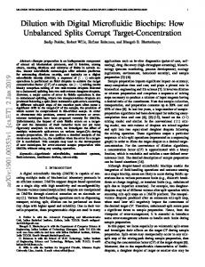
The development of microfluidic-based biochips are among the greatest engineering challenges of the century. This field lies at the interfaces between engineering (electronic and mechanic), chemistry and biology; and aims to develop lab-ona-chip (LOC) systems. LOCs represent a promising alternative to conventional laboratories because they are able to integrate on-a-chip all the basic functions for biochemical analysis. Microfluidic biochips are based on the control and manipulation of sub-millimeter fluids. Several operations like transporting, splitting, merging, dispensing, mixing and detecting are performed to the liquid under analysis. The execution of these processes is established in the assays protocols and carried out by the different modules that constitute the biochip. Fig. 1 represents a biochip composed by various modules, input and output ports and some reagents reservoirs. Nowadays there are two types of microfludic biochips. One type is based on the manipulation of continuous liquid flow, using external pressure sources or integrated mechanical micro-pumps. The other type is based on the electronic manipulation of discrete droplets on a two-dimensional array of similar modules. Several researchers concentrate their efforts on the latter type of biochips –also known as digital biochips–, due to their promising future of high-level integration and wide range of applications. The increasing use of digital microfluidic biochips for in vitro analysis, DNA extraction, drug discovery, diagnosis, among others; demands a top-down design methodology and Computer-Aided Design (CAD) tools for large scale fabrication. Moreover, many biochips will be used in safety-critical applications such as patient health monitoring, neonatal care, and environmental toxins detection. Therefore, these biochips must be fault-tolerant in order to continue operating reliably in the presence of faults. Thus, fault tolerance becomes a critical design criterion. Digital biochips also need test support that the semiconductor industry now enjoys and takes for granted. CAD tools and synthesis processes can also provide the means
Fig. 1.
Biochip: array of modules [1].
Some have questioned if is possible to automate the design of microfluidic biochips in the same way of Very-Large-Scale Integration (VLSI) of integrated circuits, and to collect the harvested by Electronic-Design-Automation (EDA) algorithms. In [2] was introduced one of the first system-level approaches, where, the focus of the unified high-level synthesis and module placement methodology was on deriving an implementation that can tolerate faulty modules in the biochip array. The next section of this paper presents a brief review of the history of microfluidic biochips. There, we also show the two main generations of biochips and some of their characteristics. Section III discusses about design trends and reviews a topdown design methodology that encompasses synthesis, testing and reconfiguration. In Section IV we reference common structural and functional defects that could derive on parametric or catastrophic faults. Section V identifies and exposes the challenges. Finally, we draw the conclusions in Section VI. II.
M ICROFLUIDIC B IOCHIPS
Basically, microfluidic biochips are lab-on-a-chip devices compounded of glass or plastic chips with etched channels through which can be maneuvered nano –or even– picoliters of liquids. Biochips can be seen as miniaturized laboratories that are able to perform up to thousands of simultaneous biochemical reactions. The main idea is to integrate all the necessary functions for diverse biochemical analysis within the same chip, while using microfluidics technology [4]. DNA analysis, water desalination, toxic detection [5] and drug delivery [6] are just few examples of industrial applications. Furthermore, the biochip technology is extended to the medicine field, into wide areas as health monitoring, neonatal care, personal healthcare [7] and regenerative medicine [8].
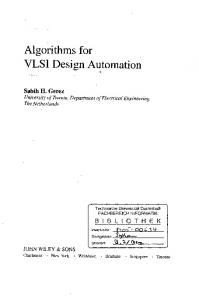
Fig. 2.
Electroosmotic function representation [4].
Current biochips are based on the concept of a DNA microarray, in which pieces of DNA known as probes are affixed on a solid substrate (glass, plastic or silicon). These chips are employed to screen biological samples simultaneously in order to detect the presence of many genetic sequences at once. In the literature can be distinguished two different generations of biochips. Based on the liquid manipulation technique, they are denoted as continuous-flow and discrete-flow (dropletbased) microfluidic biochips. The latter is the most promissory technology for large scale fabrication and the main interest of various research groups [9], [10]. Their characteristics may allow design and fabrication approaches similar to those for standard-cells in VLSI. A. Continuous-flow The biochips constructed under this technology compound the first generation of microfluidic LOCs, which manipulate the continuous flow of liquids through microfabricated channels. Continuous-flow devices are mainly used for well-defined and simple biochemical applications. Mostly because they are easy to implement and less sensitive to common problems related to proteins absorption. Otherwise, they are less suitable for tasks requiring a high degree of flexibility and preciseness. Furthermore, these biochips are more difficult to integrate and scale because liquid parameters like pressure, fluid, resistance, and electric field vary along the path flow. It means that those attributes at any location are dependent on the properties of the entire system. The manipulation of the liquid flow is done either by external pressure sources, mechanical micropumps, or by electrokinetic mechanisms like electroosmosis [11] (i.e. the motion of an ionic fluid across a porous material due to an electrical field). The Fig. 2 represents a liquid unit between two glass plates subject to a voltage source. When an electric field is applied, the movement of mobile charges in the diffuse layers pulls the liquid with them. B. Droplet-based (Digital) A digital approach appeared as an alternative to the previous continuous system. In the droplet-based microfluidics, all molecular processes are confined to the volume of a single drop. The drops are independently controlled to move on the substrate according to the assays protocols. It allows a strong reduction of reagent volume and reaction time. This generation of LOCs produces fast and efficient mixing, resulting in high throughput experiments [12]. Chakrabarty in [3] mentions as limitations of digital microfluidics biochips: the nonspecific adsorption of reagents and samples to the electrode surface, and the difficulty in ensuring accuracy and reproducibility for the droplet split operation. Nevertheless, a digital platform can facilitate the use of a cell-based design for biochips fabrication
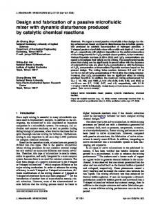
in the same way VLSI addresses the problem of manufacturing complex transistors-based integrated circuits. Reconfigurability is a notorious characteristic of a system assembled with microfluidic modules. Due to the ability of reorganization, a digital biochip can be exploited for several assays and adapted as required after its fabrication. The modular characteristic allows one to incorporate specific test modules for integrated defect/fault tolerance detection. Making the digital system a more flexible, reliable and scalable architecture when compared to its continuous counterpart [4]. Various methods exist for manipulating microfluidic droplets and control their movement through the assays. According to [4], those methods can be classified as chemical, thermal, acoustic and electrical. Within these groups, the following methods are the most used: Electrochemical, Thermocapillarity, Acoustic, Dielectrophoresis (DEP) and Electrowetting-On-Dielectric (EWOD). DEP and EWOD are the two main electrical methods. The former relies on the application of high-frequency alternating-current voltages, while the latter employs direct-current voltages or low-frequency ac. Dielectrophoresis is based on the electrokinetic phenomenon know as electrophoresis, that is the motion of dispersed particles in the liquid under the influence of a spatially uniform electric field. Electrowetting is essentially the modification of the wetting properties when applied an electric field. We can modulate the interfacial tension by controlling the electric field between a conductive fluid and a solid electrode coated with a dielectric layer. A basic unit cell of a digital microfluidic biochip based on EWOD is built with two parallel glass plates as shown in Fig. 3. The bottom plate contains a patterned array of individually controllable electrodes and the top plate has a continuous grounded metal. In order to maneuver a droplet, a voltage is applied to the contiguous electrode located in the desirable direction, while the electrode just under the droplet is deactivated. The accumulation of charge in the droplet/insulator interface results in a interfacial tension gradient across the gap between the adjacent electrodes, causing the movement of the droplet.
Fig. 3.
Basic unit cell in a EWOD-based microfluidic biochip [1].
III.
S YNTHESIS T ECHNIQUES
The shrinking size of microfluidic biochips components and the increasing demand of concurrently assays, require system-level design automation tools to handle biochip’s actual design complexity. Its design has benefited from the MicroElectro-Mechanical Systems (MEMS) growing development. However, because of the differences between MEMS and microfluidics, the first one cannot be directly used for the design of biochips. MEMS design is a relatively new field when compared to integrated circuits design. Therefore, synthesis of digital biochips can benefit from classical EDA techniques
[13]. Chakrabarty et al. [3], [14], proposed to divide the synthesis of digital microfluidic biochips into two phases: Architecture-level synthesis (High-level for IC) and Geometrylevel (corresponding to Physical-level in IC). The architecturelevel synthesis refers to the mapping from assay operations to available functional resources. Complementary, the geometrylevel addresses the placement of resources and the routing of droplets while satisfying desired objectives [3]. Below we expose the phases of system-level design methodology they propose. A. Architectural-level Synthesis The aim here is to generate a structural view of a biochip design by modeling the droplet-based assay protocols with sequencing graphs and then formulate an optimal-scheduling problem to determine the execution times of assays. In this phase is also necessary to satisfy resource constraints for assay scheduling. Avoiding the concurrently execution of assay operations when they share resources (modules). To respect the constraints, a resource binding (mapping) might associate one functional resource with one or several assay operations of the same type (resource sharing). The macroscopic biochip structure generated in the architectural-level synthesis is analogous to a structural register-transfer level (RTL) model in EDA. Su and Chakrabarty [15] developed an optimalscheduling strategy based on integer linear programming to address the problem of assay scheduling operations under resource constraints. B. Geometry-level Synthesis In this phase the authors define the final biochip’s layout. The main goal is to address the placement of modules and the routing of droplets, while satisfying objectives such as area and throughput. The final position of the modules is based on the optimal-scheduling result obtained from the architecturallevel synthesis. The ability to reconfigure the microfluidic array during assay operations and the need of fault tolerance considerations, make the biochip placement problem diverge from placement in electronic design [14]. [16] presents a geometry-level methodology supported by the classical placement techniques. Fault tolerance and area minimization are the targets. They developed a heuristic approach based on simulated annealing to solve the problem in a “computationally efficient manner”. The results showed smaller biochips with high fault tolerance. When the microfluidic modules are positioned, is necessary to define the droplets routes. Again, the assay scheduling and available resources characterize the droplet routing. The inherent reconfigurability of digital biochips allows different droplet routes to share modules on the microfluidic array during different time intervals. In this sense, the routes in biochips are not strictly defined, they can be viewed as virtual routes [3]. Diverse constraints must be satisfied during routing, most of them related to fluid properties (i.e. steady and unsteady flow, velocity and mixing), making it different from routing in VLSI. Additionally to the previous constraints, disjoint routes to avoid cross-contamination of droplets must also be considered. In a set of disjoint routes, the droplets do not share any cells. The problem of finding feasible disjoint routes in the 2-D microfluidic array can be directly mapped
to the problem of finding disjoint paths –vertex-disjoint or edge-disjoint– for pairs of vertices in a graph. The approach proposed by Chakrabarty et al. [3], [14], considers that the execution of assays is constrained to virtual devices, whose position on the microfluidic array is determined during the placement step. Thus, the routes have predefined start and end points. In [1] is eliminated the concept of virtual modules and allowed the droplets to move on the chip on any route during assays execution. Thereby, the complete geometrical synthesis problem is transformed into a routing problem. The authors presented a Greedy Randomized Adaptive Search Procedure (GRASP)-based routing algorithm for establishing the routes. With this, they try to reduce the assays execution time instead of minimize the routes length, avoiding cross-contamination and guaranteeing a small biochip size. IV.
FAULTS AND T ESTING
Faults in droplet-based microfluidic systems can be classified as being either catastrophic or parametric [3]. Catastrophic faults lead to a complete malfunction of the system, while parametric faults cause degradation in the system performance [17] and they are detectable only if the deviation exceeds a tolerable level. At [3] are exhibited examples of faults and fault models for digital biochips. From this compilation, we may mention the following catastrophic faults caused by physical defects: • Dielectric breakdown: Due to the use of high voltage levels,
the dielectric can break creating a short between the droplet and electrodes. • Short between adjacent electrodes: If a short occurs between two or more adjacent electrodes, is formed one longer electrode that suppress the electrowetting effects and, in consequence, the droplets can no longer be transported. • Insulator degradation: When it occurs, droplets are often fragmented and their motion is reduced along the flow path. Biochips with parametric fault modules can be reconfigured dynamically and those faulty modules bypassed without compromising the normal operation of the assays. But sometimes, a reconfigured biochip may presents throughout degradation due to the chosen array of cells. The absence of important modules in the final array can increase the execution time of specific assays. Some common parametric faults are: • Electrode-stuck-on: Due to the actuation for excessive duration, the electrode remains constantly activated, provoking unintentional droplet operations. • Change in droplet viscosity and filler medium: Can occur due to an unexpected biochemical reaction, or changes in operational environment like temperature variation. • Geometrical parameter deviation: The deviation in insulator thickness, electrode length and height between parallel plates may exceed the tolerance performance of the system. An efficient test plan ensures that testing will not conflict with the normal assay execution, and that it does cover all the unit cells available for testing. In digital microfluidic biochips can be implemented on-line and off-line testing techniques. Both of them could be used to detect defects caused either by fabrication or by parametric variations along the time [17]. Including additional test-oriented modules inside
biochips, self-tests are applied without the need of bulky and expensive external test equipment. In some cases the faults are easily detectable, for example to find a faulty electrode, it is sufficient to move a test droplet from the test module through a predefined route [3]. This type of tests focuses only on physical defects and overlooks module functionality. To check whether groups of modules can perform certain operations (e.g., droplet mixing and splitting), functional tests must be applied. [18] presents a Built-In Self-Test method that utilizes microfluidic logic gates to implement the compactor technique. Using the principle of EWOD, microfluidic AND, OR and NOT gates are performed through basic droplet-handling operations such as transportation, merging and splitting, in order to detect malfunction modules. When faults are detected, the module arrays can be reconfigured dynamically without interrupting the normal operation.
assays on a chip. A top-down system-level design methodology is required to address the associated design challenges. The approaches with this methodology not only have to reduce the design cycle time and time-consuming redesign efforts, but they must also deal with design-for-testability (DFT) and designfor-reliability (DFR) issues efficiently. Future computer-aided tools for the design of digital microfluidic biochips can rely on EDA development. With suitable CAD tools and an efficiency system-level methodology, the automation design of digital microfluidic biochips could reach the same developmental level of VLSI circuits. R EFERENCES [1]
[2]
V.
C HALLENGES
The continuous growth in the emerging field of digital biochips depends on advances in system integration. Automated design methods are needed to ensure that biochips will be as versatile as the conventional laboratory equipments they are intended to replace. EDA-based techniques can allow biochips users to concentrate on the development of assays, leaving chip optimization and implementation details to design-automation tools. In the actual phase of development, system-level approaches need to be coupled with more detailed data for physical simulation and verification. The design rules that must be verified in the droplet-based biochips are significantly different from those in IC. Hence, the determination of accurate and efficient design rules for physical verification of digital biochips is a challenge for future design tools, as [4] points out. In terms of faults detection and testing, some physical mechanisms that may result in failures are not yet well understood and they are difficult to detect. Design-for-test techniques need to be improved in order to facilitate the discovery of parametric faults, which are harder to detect than the catastrophic faults, and avoid them. Most of the commercial biochips available today are specific for an application, but in the future, they ought to offer a high level of flexibility in terms of functionality. Digital biochips can benefit from the progress of nanotechnology. In a nanoscale, the shrinking size of components could lead to a large scale of integration, allowing the inclusion of modules intended for various applications into the same biochip. VI.
C ONCLUSION
We have presented a survey on design automation and test techniques for microfluidic biochips. We first review the microfluidic platform, then highlighted the characteristics of droplet-based biochips and the methods for manipulating microfluidic droplets. Testing and design-for-testability techniques have also been presented and common defects have been identified. Finally, the main design and fabrication challenges were showed and briefly discussed. The level of system integration and the complexity of digital microfluidics biochips are expected to increase in the near future due to the growing need for multiple and concurrent
[3]
[4]
[5]
[6]
[7]
[8]
[9] [10] [11]
[12]
[13] [14]
[15]
[16]
[17]
[18]
E. Maftei, P. Pop and J. Madsen, Routing-based synthesis of digital microfluidic biochips. Design Automation for Embedded Systems, pp.19– 44, 2012. F. Su and K. Chakrabarty, Unified high-level synthesis and module placement for defect-tolerant microfluidic biochips, in Proceedings of the Design Automation Conference, pp. 825–830, 2005. K. Chakrabarty, Design Automation and Test Solutions for Digital Microfluidic Biochips, in IEEE Transactions on Circuits and Systems, vol. 57, no. 1, pp. 4-17, 2010. F. Su, K. Chakrabarty and R. B. Fair, Microfluidics-Based Biochips: Technology Issues, Implementation Platforms, and Design-Automation Challenges, in IEEE Transactions on Computer-Aided Design of Integrated Circuits and System, vol. 25, no. 2, pp. 211–223, 2006. D. Chatterjee, B. Hetayothin, A. R. Wheeler, D. J. King and R. L. Garrell, Droplet-based microfluidics with nonaqueous solvents and solutions, Lab on a Chip, vol. 6, pp. 199–206, 2006. J. G. Santiago, S. Litster, E. Junco and M. Suss, (2013, June) Electroosmotic Pumps for Drug Delivery. [Online]. Available: http://microfluidics.stanford.edu/Projects/Current/EOPumps DrugDelivery.html (2013, April) Intel Health Guide PHS6000, product brief. Intel Corporation. [Online]. Available: http://www.intel.com/corporate/healthcare/ emea/eng/healthguide/pdfs/Health Guide Product Brief-UK.pdf B. Harink, S. Le Gac, R. Truckenm¨uller, C. A. van Blitterswijk and P. Habibovic, Regeneration-on-a-Chip? The perspectives on use of microfluidics in regenerative medicine, Lab on a Chip [Accepted manuscript], 2013. (2013, July) Digital Microfluidics, Duke University. [Online]. Available: http://microfluidics.ee.duke.edu/ (2013, June) Standford Microfluidics Laboratory website. [Online]. Available: http://microfluidics.stanford.edu/index.html S. Mutlu et al., Enhanced electro-osmosis pumping with liquid bridge and field effect flow rectification, in Proc. IEEE Micro Electro Mechanical Systems (MEMS) Conf., Maastricht, The Netherlands, pp. 850–853, 2004. (2013, June) Insights on digital microfluidics, The Fluigent website, Feb. 2013. [Online]. Available: http://www.fluigent.com/blog/articles/182digital-microfluidic/ G. De Micheli, Synthesis and Optimization of Digital Circuits, MacGraw-Hill, 1994. F. Su and J. Zeng, Computer-Aided Design and Test for Digital Microfluidics, in Proc. IEEE Design and Test of Computers, vol. 24, no. 1, pp. 60–70, Jan. 2007. F. Su and K. Chakrabarty, High-level synthesis of digital microfluidic biochips, in ACM Journal on Emerging Technologies in Computing Systems, vol. 3, Article 16, 2008. F. Su and K. Chakrabarty, Module Placement for Fault-Tolerant Microfluidics-Based Biochips, in ACM Transactions on Design Automation of Electronic Systems, vol. 11, no. 3, pp. 682–710, July 2006. F. Su, S. Ozev and K. Chakrabarty, Testing of Droplet-based Microelectrofluidic Systems, in Proc. IEEE International Test Conference, pp. 1192–1200, 2003. Y. Zhao, T. Xu and K. Chakrabarty, Built-in self-test and fault diagnosis for lab-on-chip using digital microfluidic logic gates, in Proc. IEEE International Test Conference, 2008.