Procedia Engineering
Available online at www.sciencedirect.com
Procedia Engineering 00 (2011) 000–000
Procedia Engineering 30 (2012) 226 – 233
www.elsevier.com/locate/procedia
International Conference on Communication Technology and System Design 2011
A Novel Methodology for Memory Reduction in Distributed Arithmetic Based Discrete Wavelet Transform Remya Ajai A Sa, Nithin Nagarajb, a* a,b
Department of Electronics and Communication Engineering, Amrita School of Engineering, Amrita Vishwa Vidyapeetham, Amritapuri Campus, Kollam, Kerala, India 690 525
Abstract Discrete Wavelet Transform (DWT) is widely used in image compression standards such as JPEG 2000. DWT can be implemented on FPGA using parallel Distributed Arithmetic (DA) architecture, which is suitable for low power implementation. However, the size of the memory in DA increases with the number of wavelet coefficients. In this paper, we propose a novel methodology to reduce the size of the Look-Up Tables (LUTs) used in DA for DWT. The table entries are sorted using Burrows-Wheeler Transform (BWT) and then compressed. The compressed table is stored in memory. During DWT/IDWT computation, without reconstructing the entire table we can recover only the required table entry. A comparative study of this methodology among different wavelets is performed. We demonstrate that the method is very effective for reducing the memory of DA architectures. A compression ratio of around 2.3:1 is achieved for the look-up table which stores the inner product of high-pass filter coefficients of Daubechies-4 (Db4) wavelet which is used in JPEG2000.
© 2011 Published by Elsevier Ltd. Selection and/or peer-review under responsibility of ICCTSD 2011 Open access under CC BY-NC-ND license.
Keywords: Discrete Wavelet Transform; Burrows-Wheeler Transform; Distributed Arithmetic Architecture; Daubechies-4 Wavelet
1. Introduction The wavelet transform is an effective signal processing technique that can be used to represent real-life non-stationary signals with high efficiency [1]. The Discrete Wavelet Transform (DWT) is used for image compression such as in JPEG-2000 [2]. Recently several VLSI architectures have been proposed to realize single chip designs for DWT ([3] – [6]). Traditionally, such algorithms are implemented using programmable chips for low-rate applications, or VLSI application specific integrated circuits (ASICS) for higher rates. The main power consuming operation in DWT is filtering. Distributed arithmetic (DA) architecture can be adopted to eliminate the requirement of multiplication, which may lead to a reduction * Remya Ajai A.S. Tel.: +91-0476-2801280. E-mail address:
[email protected]. 231
1877-7058 © 2011 Published by Elsevier Ltd. Open access under CC BY-NC-ND license. doi:10.1016/j.proeng.2012.01.855
227
Remya Ajai A S and Nagaraj / Procedia Engineering 30 (2012) 226 – 233 Remya Ajai Nithin A S,et.,al / Procedia Engineering 00 (2011) 000–000
of power consumption [7]. However, for a wavelet with larger number of coefficients, the advantage of using DA may eventually be lost as there will be a significant increase in memory size. As the number of filter coefficients n increases linearly, the number of table entries required is 2n which implies an exponential increase in the size of the look-up table. In this paper, we propose a novel methodology for memory reduction in the DA-based design of DWT/IDWT architecture by exploiting the look up table compression technique. The table entries are first sorted using Burrows-Wheeler Transform (BWT) and then compressed using a look-up table compression algorithm. The performance of compression can be increased if the tables can be divided into different blocks. But the number of reverse BWT operations to be performed will increase. Thus, there is a trade off between compression ratio and speed. The paper is organized as follows. In Section 2 we discuss the existing DA architecture for DWT implementation. In Section 3, we propose our novel memory reduced DA architecture which makes use of BWT and a look-up table compression algorithm. Implementation details, results and comparative evaluation of the proposed method are discussed in Section 4. We conclude in Section 5. 2. Existing methods for DWT implementation In this section, we give a brief description of the parallel DA implementation of DWT. The DWT of a signal x(n), is calculated by passing it through a series of filters. First the samples are passed through a low pass filter with impulse response g(n) resulting in a convolution operation: (1) The output of low-pass filter will provide the approximation coefficients. The high-pass filter h[n] will also decompose the same signal simultaneously and gives the detail coefficients. According to Nyquist‟s rule, half the samples can be discarded and hence half the frequencies of the signal have now been removed. The filter outputs are then down sampled by 2. (2) (3) 2.1. Distributed Arithmetic Architecture All digital signal processing linear filtering algorithms can be represented in sum of product forms. The hardware implementation of these algorithms requires multipliers and accumulators. Multipliers are costlier and hence can be replaced with shifts and look-up tables which are suitable for low power portable applications [8]. Distributed Arithmetic (DA) architecture is implemented for effectively performing the inner product calculations [9]. DA is basically a bit-serial computational operation that forms an inner product of a pair of vectors in a single direct step. The equation that defines a distributed arithmetic computation is given below: (4) Consider the term . Each may take on values of 0 and 1 only and hence there will be possible values. Rather than computing these values on line, we may pre-compute the values only 232
228
Remya AjaiAjai A SAand Nithin Nagaraj Engineering / Procedia Engineering 30 (2012) 226 – 233 Remya S,et.,al / Procedia 00 (2011) 000–000
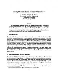
and store them in ROM. The input data can be used to directly address the memory and the result can be directly fed into an accumulator. After N such cycles, the memory contains the result y. 2.2. Parallel DA Implementation of DWT Finite Impulse Response (FIR) filters can be used for realizing the pyramid tree structure of a DWT. The transfer function of these filters can be represented as: (5) (6) The DWT coefficients, which consist of coefficients and delays, are generated after passing through the high pass and the low pass filters. For performing the filter operation with l input variables, the filter coefficients are convolved with inputs. Here the coefficients are fixed. Inputs can be represented in binary. Inputs are scaled such that their absolute values will be less than 1. The inner product for various inputs can be computed and stored in advance, in ROM look-up tables. If there are n wavelet coefficients, then the size of the look-up table will be 2n. All LSBs are considered to get the first address. This address is used for getting the first data. Similarly, all bit positions are obtained and the corresponding values are taken from the look-up table. The values are shifted by the bit position while adding. Once the MSB bits are also processed, we have the convolution output. Implementations of both high-pass and low-pass filters are done with the help of the same architecture. Here the filter coefficients are in fractional form. To represent them in binary form, more bits are needed. Hence, the number of computations will increase. So, the values are rounded off to integers. To speed up the process, we can go for parallel implementation of the DA [9]. In parallel implementation, the input is applied sample by sample, in a bitparallel form. Hence each sample will convolve with the corresponding coefficients at the same time. 3. Memory Reduced DA Implementation In the traditional implementation of DWT with DA architecture, all the possible combinations of filter coefficients are to be stored in memory. This may increase the speed of computation but the memory size will increase with the number of wavelet coefficients. Thus the advantage of using DA will be effectively lost. In this section, a novel methodology for reducing the size of the look-up table in DA architecture for DWT is proposed. The look up table used to store all the possible combinations of input in DA architecture can be reduced using a table compression algorithm. In [10], this algorithm is used for compressing the lookup tables used to store assembly language instructions of a processor. The same algorithm can be efficiently implemented for reducing the LUTs of DA architecture. 3.1. Look-Up Table Compression [10] The size of the look-up table (LUT) can be reduced by identifying the number of toggles between every two successive entries and then compressing it. The principle of compressing the table is to minimize the number of bit transitions per column and then saving the indices only where a bit toggle occurs instead of saving the complete column. Fig. 1 shows an example for a LUT with 7 symbols and 8 bits each. The size of the table (before compression) is 56 bits. The number of unique binary words in the table is 8 where index length is equal to 3 bits. Hence, the column can be compressed if it has a maximum of 2 transitions (because more than 2 transitions will need more than 7 bits which was the cost of the uncompressed column). In that case, 7 columns will be compressed and one column will be left without compression. The size of the table after compression is minimized to 34 bits (from 56 bits before). The compressed table is stored in FPGA RAM blocks. 233
229
Remya Ajai A S and Nagaraj / Procedia Engineering 30 (2012) 226 – 233 Remya Ajai Nithin A S,et.,al / Procedia Engineering 00 (2011) 000–000
Fig.1. An example of the Table Compression algorithm of [10]
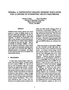
3.2. Look-Up Table Decoding In this decoding technique, the required inner product value is generated from the compressed look-up table. When a particular input to look-up table arrives, it finds out its position in each column of the compressed table. If it is in an even position, a „0‟ is generated; otherwise it generates a „1‟. The original bits of uncompressed table columns are retrieved directly from the ROM. The accumulator concatenates the bits in the correct positions and generates the decompressed data. Consider the example in Fig. 1. If the input is „101‟, the bit in the position 1 is „1‟ since a toggle occurs at „000‟. For the second column, the input „101‟ is greater than the first two entries. This means that toggle occurs twice and hence the bit in that position will be 0. For the 7th position, it will directly take the sixth entry in the uncompressed column. Similarly we can obtain the bit in all the positions. In our example, we will get the decompressed data as “10101011” which is the original data with index „101‟ in the original table. 3.3. Burrows-Wheeler Transform The size of the LUTs will vary with the type of wavelet since the number of coefficients for a particular wavelet varies. For Daubechies 8-tap wavelet, the size of the look-up table is 256. After rounding, each entry will be of 9 bits. So total of 2304 bits are needed to store in the LUTs. Altogether, four such tables are to be implemented and will need a total of 9216 bits to be stored in memory. Using the table compression algorithm, we can reduce this to 8667 bits. Since the coefficients for a particular wavelet are fixed, the compressed table for a wavelet can also be fixed. So, while implementing the compressed table in FPGA, we can store minimum number of bits for representing a particular table index and read accordingly while decoding. In this way, the number of bits needed to be stored gets decreased further. The compression ratio obtained can be further improved by applying Burrows-Wheeler transform (BWT), which is a traditionally used pre-compression algorithm for strings [11]. The main principle behind BWT transformation is that if the original string contains several substrings which occur frequently, then a transformed string which will have a single character repeating multiple times in a row at various places can be generated. Thus the transformed string has more redundancy and hence can be compressed more efficiently than the original string. 3.4. Efficient Look-Up Table Compression with BWT The block diagram for memory reduced DA architecture is given in Fig. 2. The look-up table entries are represented in binary and treated as a single row of elements. The data is then sorted using BWT 234
230
Remya AjaiAjai A SAand Nithin Nagaraj Engineering / Procedia Engineering 30 (2012) 226 – 233 Remya S,et.,al / Procedia 00 (2011) 000–000
algorithm. The sorted output L of BWT is then compressed using table compression algorithm. The compressed table is stored in memory. Table sorting, compression and memory storage are offline processes.
Look-Up Table For
DA Architecture
Sorted Table using BWT Table Compression Algorithm
Offline Process
Compressed Look-Up Table (Stored in Memory)
Table Decoding Algorithm
Reverse BWT
Inner Product Output
Uncompressed Look-Up Table
Fig. 2. Block Diagram for Memory Reduced DA Architecture
At the time of decompression, the look-up table decoder will decode the corresponding L value. Using reverse BWT, the required data is obtained for further process. For getting better compression ratio, we can divide the entire table into blocks of smaller tables. The block to be decompressed can be identified with the actual index of the table. The compression ratio increases with the number of tables but at the cost of more number of reverse BWT operations to be performed. 4. Implementation and Results The design for DWT and Inverse DWT (IDWT) are implemented in MODELSIM and the output is verified with MATLAB results. Synthesis is done using XILINX ISE 10.1. The results were analysed and discussed below: 4.1. Comparison of lossless compression ratios Compression Ratio without BWT 1.2 1 0.8 H1
H0
G1
G0
Fig. 3. Compression Ratio obtained for the inner product look-up tables of H1 (forward high-pass), H0 (forward low-pass), G1 (reverse high- pass) and G0 (reverse low-pass) filter coefficients of Db4 wavelet, without sorting the table entries using BWT before compression;
235
Remya Ajai A S,et.,al / Procedia Engineering 00 (2011) 000–000
231
Remya Ajai A S and Nithin Nagaraj / Procedia Engineering 30 (2012) 226 – 233
Compression Ratio
2.5 2 1.5
H1
1
H0
0.5 0 Without BWT
With BWT
Fig. 4. Comparison of Compression Ratios of the inner product look-up tables of H1 (forward high-pass) and H0 (forward lowpass) filter coefficients of Db4 wavelet with and without BWT.
The graph shown in Fig. 3 reveals that the compression ratio (without BWT) of the look-up table containing the pre-computed inner product values for the forward high-pass filter coefficients H1 of Db4 wavelet is higher than that of other filter coefficients. The compression ratio for coefficients H0 and G1 is 1, which indicates that no compression is achieved. Fig. 4. clearly shows that application of BWT results in a higher compression ratio of LUTs. For both the forward high-pass and low-pass filters, the compression ratio is high if the tables are compressed after sorting the entries using BWT. 4.2. Comparison of lossless compression ratios obtained for various values of index l
Compression Ratio
2.5 2 1.5 1 0.5 0 1
2
4
8
16
32
64
Number on index value
Fig. 5. Comparison of the compression ratios obtained for the compression of look-up table having pre-computed inner product values, with different number of l values. The l value represents the index output of a particular BWT. 236
232
Remya AjaiAjai A SAand Nithin Nagaraj Engineering / Procedia Engineering 30 (2012) 226 – 233 Remya S,et.,al / Procedia 00 (2011) 000–000
The entire table can be divided into various blocks and BWT can be applied to each block to increase the compression ratio. The index value l is the input to BWT. So the number of BWT operation is equal to the number of l values. The graph shown in Fig. 5 reveals that as the number of index value l increases, the compression ratio also increases. This is because the number of entries in a single block decreases with increase in the number of blocks. Since the table entries are sorted using BWT algorithm, the bit change between the adjacent entries in a single block will be very less. Thus, the number of table indices to be stored also decreases. This effectively reduces the size of the compressed table. However, the number of reverse BWT to be carried out will be more with the number of blocks. If more reverse BWTs are to be performed, the time required for table decompression also increases. Thus, there is a trade of between the compression ratio and speed. 4.3. Comparison of lossless compression ratios for different wavelets
Compression Ratio of different Wavelets 2 1.5 1 0.5 0
Fig. 6. Comparison of the Compression Ratios (with BWT) of inner-product look-up tables for forward high-pass filter coefficient H1, of different wavelets.
Fig. 6 indicates that Haar has a higher Compression Ratio compared to other wavelets. This is because the number of coefficients is less for Haar. Although all our compression algorithms are lossless, since there is scaling and rounding-off in the DA implementation, there is some loss. Hence, we calculate the Mean Squared Error (MSE) and Peak Signal to Noise Ratio (PSNR) for the results obtained with normal DWT and the DWT using DA architecture with scaled and rounded coefficients using MATLAB. The calculation of MSE and PSNR for the reconstructed output using parallel DA method and the original inputs are also measured. In both the cases, results are acceptable. below:
MSE and PSNR between normal DWT and DWT with rounded coefficients are obtained as MSE = 1.4682 x 10-55, PSNR = 48.2447 dB. MSE and PSNR between reconstructed data and original are obtained as below: MSE = 1.1216 x 10⁻⁴, PSNR = 39.4144 dB. 237
Remya Ajai A S and Nagaraj / Procedia Engineering 30 (2012) 226 – 233 Remya Ajai Nithin A S,et.,al / Procedia Engineering 00 (2011) 000–000
The Mean Squared Error and Peak Signal to Noise Ratio between the actual DWT output and the output obtained from the DA with table compression algorithm for DWT for the forward high-pass filter computation are calculated and the results obtained as 2.1072 x 10⁻⁵ and 46.675 dB respectively. 5. Conclusions A novel methodology for memory reduction in DA based DWT is synthesized in SPARTAN 3 FPGA using Xilinx ISE 10.1. Implementation of distributed architecture replaced the costly multipliers for the inner product operations in the DWT computation process. The implementation is done mainly by focusing Daubechies 8-tap wavelet, which is widely used for image compression due to its high degree of reconstruction ability (it is used in JPEG2000). However, the same algorithm is implemented for other wavelets also using Matlab and the results are verified. A pre-compression algorithm - BWT, which is traditionally used for sorting strings, is used for sorting the entries of look-up table before compression. The table is then compressed and stored in ROM of FPGA. While performing DWT computation, data can be decoded by decompressing the table. The entire table can be divided into different blocks and BWT applied separately so that while decompression, only that particular block needs to be decompressed. However, this requires more BWT operations if data belongs to different blocks. Thus, there is a trade of between speed and compression ratio. A compression ratio of around 2.3:1 is achieved for the look-up table which stores the inner product of high-pass filter coefficients of Db4 wavelet. Future work will focus on optimizing the speed of retrieval from LUT and fast decoding. Acknowledgement We offer this work at the Lotus Feet of our Beloved “Amma”, Satguru Sri Mata Amritanandamayi Devi. Amma‟s constant grace and care enabled a successful completion of this research. References [1] Soman KP, Ramachandran KI., “ Insight to Wavelets From Theory to Practice”, Prentice Hall of India Private Limited, August 2005. [2] Taubman D, Marcellin M., “JPEG2000: Image compression fundamentals, standards, and practice”, Kluwer Academic Publishers, 2004. [3] Knowles G., “ VLSI architecture for the discrete wavelet transform”, Electron Letters vol. July 1990, 26, no. 15, pp. 1184-1185. [4] Grzeszczak A, Kandal M, Panchanathan S, Yeap T., “VLSI implementation of discrete wavelet transform”, IEEE Trans. VLSI System , December 1996, vol. 4, no. 4, pp. 421-433. [5] Parhi K, Nishitani T., “VLSI architectures for discrete wavelet transforms”, IEEE Trans. VLSI Systems , June 1993, pp. 191202,. [6] Chakabarti C, Vishwanath M, Owens R., “ Architectures for wavelet transforms: a survey”, Journal of VLSI Signal Processing November 1996, vol. 14, no. 2, pp.171-192,. [7] Parhi K. VLSI Digital Signal Processing Systems. John Wiley & Sons, USA, 1999. [8] Al-Haj AM. “An FPGA-Based Parallel Distributed Arithmetic Implementation of the 1-D Discrete Wavelet Transform”, Informatica vol. 29, no. 2, pp. 241-247, 2005. [9] White SA, “Applications of Distributed Arithmetic to Digital Signal Processing: A Tutorial Review”, IEEE ASSP Magazine pp. 4-19, July 1989. [10] Bonny T, Henkel J., “ Efficient Code Compression for Embedded Processors”, IEEE Transactions on Very Large Scale Integration (VLSI) Systems ,December 2008, vol. 16, no. 12, pp.1696-1707. [11] Burrows M, “Wheeler DJ. A Block-sorting Lossless Data Compression Algorithm”, SRC Research Report May 1994. 238
233