A novel modeling framework for time-triggered safety-critical embedded systems Iban Ayestaran, Carlos F. Nicolas, Jon Perez, Asier Larrucea
Peter Puschner
Embedded Systems Group IK4-Ikerlan Research Center Arrasate-Mondrag´on, Basque Country (Spain) Email: {iayestaran, cfnicolas, jmperez, alarrucea}@ikerlan.es
Institut f¨ur Technische Informatik Technische Universit¨at Wien Wien, Austria Email:
[email protected]
Abstract—This paper presents the Platform Specific Time Triggered Model (PS-TTM), a SystemC based modeling and simulation framework for time-triggered safety-critical embedded systems. The approach facilitates the modeling of Time-Triggered Architecture (TTA) based embedded systems, following a strict separation between the designs of functionality and platform. The PS-TTM provides a value and time domain deterministic simulation environment for an early functional and temporal assessment of the systems. Moreover, the framework includes a time-triggered automatic test executor that enables to perform non-intrusive simulated fault injection (SFI) to the models. The SFI makes an early dependability assessment possible, what reduces the risk of late and expensive discovery of safety related pitfalls. The feasibility of the proposed framework is illustrated with a case study, based on the modeling, simulation and validation of a simplified railway on-board signaling system.
I. I NTRODUCTION Safety-critical systems are dependable embedded systems whose improper functioning could lead to loss of human life or significant damages to the environment. The design of such systems is a complex task, since they must not only satisfy real-time requirements but they must also provide a specific behavior in the presence of both software and hardware faults. In order to relax the implicit complexity of developing safety-critical systems, nowadays their design often follows a model-based approach, where systems are modeled at high abstraction levels and they are progressively refined into lower levels. In this context we find the Y-chart development process [1], [2], [3], which specifies the functional model and the platform model of the system separately, and combines both by means of a mapping model to obtain the complete system model. This way, the Y-chart paradigm eases the comparison between the performances provided by a given functionality in different platforms, what enables the designers to argue about the suitability of each platform for that functionality. Similarly, Model Driven Development (MDD) approaches, such as the Model Driven Architecture (MDA) [4], also follow the idea of a strict separation of behavioral and platform models. Namely, MDA proposes the development of a Platform Specific Model (PSM) by applying transformations to a Platform Independent Model (PIM). Moreover, these systems have suffered a complexity growth in the latest years due to the increase in the amount of
services they provide. In order to deal with this complexity challenge, the international IEC-61508 standard for safetyrelated embedded systems highly recommends the usage of semi-formal methods. The MDD approaches implement different techniques to handle the complexity, including the three main simplification strategies identified by the community: abstraction, partition and segmentation [5], [6]. In this context, SystemC [7] is a high-level HW/SW codesign language based on C++ that enables the designers to model and simulate systems at different levels of abstraction. Thus, SystemC can be used to design, simulate and verify platform independent and platform specific models of dependable embedded systems. Given this situation, the aim of this research work is to provide a SystemC-based modeling environment for timetriggered safety-critical embedded systems, which follows the Y-chart paradigm. This paper describes the formalism of the proposed Platform Specific Time-Triggered Model (PS-TTM), which provides the following contributions: • Provides a time and value deterministic simulation environment. • Enables non-intrusive simulated fault injection for an early dependability assessment. • Tackles the complexity challenge by means of abstraction, partition and segmentation. This paper is structured as follows: Section II briefly describes previous related work, and Section III introduces the basic background concepts used along the paper. Section IV presents the PS-TTM, our approach for the modeling, simulation and verification of time-triggered safety-critical embedded systems. Section V evaluates the approach by means of a simplified railway signaling system, and Section VI describes the reliability assessment performed to the models and presents the main results. Finally, Section VII summarizes the main conclusions of the work. II. R ELATED W ORK Several modeling environments have been proposed for the development and validation of dependable systems, such as SCADE Suite [8], the Model Driven Architecture (MDA) [4] and its derivative languages (e.g. UML [9] and SysML [10]), the Architecture Analysis and Design Language (AADL) [11],
the Fault-Tolerant Operating System (FTOS) [12], and the Executable Time-Triggered Model (E-TTM) [13]. SCADE Suite is a model-based development environment for safety-critical software, based on the synchronous Model of Computation (MoC). However, this tool only covers the application functionality of embedded systems, and non-functional aspects such as the modeling of hardware components and the distribution of software in hardware platforms are not covered. The MDA suggests separating the specification of the operation of a system from the details of its deployment on a specific platform. Therefore, the MDA decouples the system in two models: PIM and PSM. This, besides reducing the cognitive complexity of systems, increases their portability, interoperability and re-usability. Different modeling languages, such as the Unified Modeling Language (UML) [9] and the Systems Modeling Language (SysML) [10], are compliant with the MDA. UML is an international standard that defines a modeling language for software systems design. However, as SCADE, UML does not directly support the design of HW components, and it is therefore not suitable to model HW/SW systems. SysML is the adaptation of UML for the development of systems including combinations of HW, SW, data, people, facilities and objects. However, since it is a general purpose language, it is not restricted to a specific MoC, what hinders the generation of executable models from SysML designs. AADL is a modeling language for the development and analysis of embedded systems with multiple critical operational properties, such as responsiveness, safety-criticality, security, and reliability. In contrast to the MDA, AADL defines the system and all its components in a unique hierarchical model. It is mainly focused on the aerospace industry. FTOS is a model-based design tool for fault-tolerant automation systems. Unlike MDA or AADL, FTOS decouples the system in four different models: the HW architecture model, the SW architecture model, the fault model and the fault-tolerance mechanisms. It provides a time deterministic environment relying on the Logical Execution Time MoC [14]. However, to the best of our knowledge, there is still no modeling, simulation and verification framework for time-triggered safety-critical embedded systems that enables HW/SW cosimulation and allows performing non-intrusive simulated fault injection for an early dependability assessment. III. BACKGROUND This section describes some basic background concepts that we use in this paper. A. SystemC SystemC [7], is an open-source system-level modeling language which enables one to develop executable models of HW/SW systems at different levels of abstraction. SystemC provides an event-driven simulation engine that eases the simulation of concurrent processes using plain C++ syntax. Events are instantaneous in SystemC, and simulation time of processes is zero. Therefore, the processes triggered by a given
event are executed concurrently. Due to its capability to model HW and SW components in a single language and its ability to simulate concurrent processes, SystemC has nowadays become the de-facto standard in HW/SW system design. B. Executable Time-Triggered Model (E-TTM) The E-TTM [13] is a SystemC based extension for the modeling of the functionality of real-time embedded systems based on the Time-Triggered Architecture (TTA) [15]. It extends SystemC with the sparse notion of time, and decouples computation activities from communication, while they both share a global notion of time. The execution of computational components in E-TTM is instantaneous and restricted to the sparse-time macrotick. As in SystemC, simultaneously triggered components are executed sequentially, but the output messages are not delivered during the execution macrotick and the events generated during the computation do not trigger activation events until next macrotick. This guarantees that the execution order chosen by the E-TTM scheduler for simultaneous jobs does not influence the values or temporal properties of the outputs of the system. Communication between components takes place during the silence interval of the sparse-time model and is quasiinstantaneous. However, E-TTM enables one to delay the transmission of a message in order to represent the amount of time that computation or message-exchange take in the real world. C. Logical Execution Time (LET) The concept of Logical Execution Time (LET) [14] was first introduced with the Giotto time-triggered programming language [16]. The LET MoC is a time-triggered MoC that specifies a logical duration for each computational job, regardless of its physical duration. Therefore, the LET paradigm is well suited for time-triggered systems that exhibit timeperiodic behavior. The logical execution time of a given job specifies the duration between the instant when the inputs are read and the instant when the outputs are written, considering that the communications are instantaneous. In case the program completes its execution before the deadline of the LET, the update of the outputs is delayed until that deadline. In other words, the LET of a job is the upper bound of its physical execution time. Due to the decoupling of physical and logical execution times, when the deployment of the model into a hardware platform satisfies the LET specification, the behavior of the system does not get influenced by the platform. The LET specification is satisfied if the following conditions hold: • The (physical) worst case execution time (WCET) of a job is not longer than the LET. • The platform ensures that the inputs of a job are read at the beginning of the LET interval and outputs are written at the end of the LET interval. Whereas the first condition depends to a great extent on the technology of the HW components, the second condition is
inherent to the system when the LET model is mapped onto TTA platforms. C-COMPONENT
IV. T HE P LATFORM S PECIFIC T IME -T RIGGERED M ODEL (PS-TTM) This section describes the Platform Specific Time-Triggered Model (PS-TTM), the proposed SystemC based value and time deterministic modeling framework for time-triggered safetycritical embedded systems. Our approach is based on the Y-chart development process and the MDA. Thus, first the functionality of the system is described in a platform independent model. The PIM is an executable model that allows the designers to check the logic of an application at an early stage of development without concerning about all the constraints of the target environment. Once the PIM is completed and its functionality is verified, it is transformed to its platform specific representation, the PSM, by deploying the components of the PIM into a target platform model. PSMs consist of a set of PSM jobs distributed over different PSM containers, where the PSM container is a concrete HW component for the execution of the job on a specific platform. The decoupling between the design of functionality and the design of the platform saves design time and cost during the development process, and enables the early validation of the system. Furthermore, it eases the assessment of the emerging behavior of a given functionality in several platform variants. The PS-TTM is built as an extension of the E-TTM library that enables one to model both PIMs and PSMs, and provides mechanisms to perform non-intrusive simulated fault injection in the models. Following the approach presented in [6], components in PS-TTM are classified into computational components (c-components) and interface components (i-components). C-components get input data, perform some computation and produce output data, whereas i-components behave as gateways. The components are defined following the description given by Kopetz et al. [17], [18], i.e., they contain four different interfaces: the Linking Interface (LIF), where the components communicate with other components; the Configuration and Planning (CP) Interface, where components can be configured; a Diagnostic and Management (DM) Interface, where the internal elements of a component can be observed; and the local interfaces to the environment. In contrast to E-TTM, all computational components in the PS-TTM are triggered by time. This increases the timing predictability of the systems, what makes it well-suited for safety-critical embedded systems. The complexity challenge is tackled by providing a global notion of time throughout the system and enabling to apply abstraction, partition and segmentation to the models. Abstraction is provided by the ability to define hierarchical systems, where atomic jobs are placed over different hierarchical components. Partition is enabled in two ways: first, the system may be partitioned into independent components, each of them
i- component
C-COMPONENT
Communication Channel
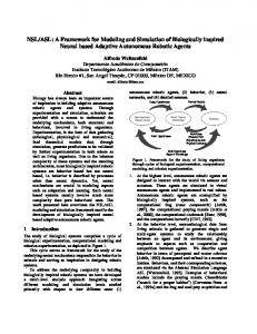
Fig. 1: PS-TTM: architecture of hierarchical components
performing different parts of the overall functionality. Second, the PS-TTM separates computation and communication concerns. Finally, segmentation is provided by automatically setting the sequential order of execution of simultaneous jobs. Figure 1 shows the architecture of hierarchical components in PS-TTM. The elements shaded in gray are given by the modeling framework. Functional verification of the system is performed by simulating the system against different test cases. However, the verification of the non-functional properties of a system usually requires the injection of faults in the system. Therefore, the PS-TTM provides a time-triggered testing and simulated fault injection framework, called PS-TTM Automatic Test Executor (ATE) [19]. This framework enables the testing team to perform non-intrusive simulated fault-injection in both platform independent and platform specific models. The PS-TTM ATE shares the global notion of time with the models under test. In order to perform fault injection, the testing team needs to define the desired fault injection campaign and provide it to the PS-TTM ATE during the initialization phase of the simulation. During the execution, the PS-TTM ATE supervises all the communications that take place in the model, compares them to the fault injection campaign, and sabotages the signals as required. This process is performed instantaneously. Faults can be defined as transient or permanent. Permanent faults remain active until the simulation ends, whereas transient faults are temporary misbehaviors whose duration is defined in the fault configuration. The fault injection campaigns are defined in XML files. The selected XML schema complies with the international ASAM AE HIL [20] standard for hardware in the loop testing, what facilitates the forward reuse of the fault injection campaigns until the final prototype. The PS-TTM includes a graphical tool (GUI) for the definition of fault injection campaigns in order to simplify their design and avoid configuration errors. Although the properties specified above are common for all models in PS-TTM, the PIMs and PSMs differ in the details specified in the following sections. A. Platform Independent Models 1) Underlying MoC: In order to make the deployment of PIM models into TTA platforms straightforward while
Fig. 2: PI-TTM: Relationship between LET and E-TTM MoCs
Boolean
TABLE I: Fault library for PIM models
Integer / Float
preserving the simplicity of the functional models, the PSTTM relies on the LET MoC for the definition of platform independent models. The LET MoC avoids synchronization points during the execution of jobs and triggers all the jobs synchronously. This reduces the number of failures that might occur in the system, since the absence of failures due to faulty synchronization points and different orders of execution is guaranteed by the MoC. 2) Architecture of models: The PIMs rely on the architectural hierarchy described in [13], where computational components can be defined as systems, distributed application subsystems (DASes) and jobs. Systems and DASes are abstract hierarchical components, whereas jobs are atomic components. An example of a PIM architecture can be seen in Figure 3. LET models are cyclic over time. Hence, system components contain an attribute named period, which must be set by the designers and establishes the duration of its periodic behavior. DASes and jobs, however, specify their frequency, which states how many times the component is executed per period. Therefore, the frequency of a job together with the period of the hierarchical component where it is located, determine its LET. 3) Execution and communication: The PS-TTM includes a novel LET based simulation engine called Platform Independent Time-Triggered Model (PI-TTM) [21]. The PI-TTM library handles the simulation of the LET-based models in SystemC by means of the E-TTM execution engine. To do so, PI-TTM automatically calculates the schedule of the LET system by setting the triggering instant of each job according to its logical execution time. Communication between components is performed by pushing/pulling shared variables stored in the communication channels of hierarchical components. The temporal constraints imposed by the LET MoC are guaranteed by the PI-TTM execution engine, which automatically delays push actions until one delta-cycle before the next triggering instant of the job, whereas performs pull actions instantaneously one deltacycle before the execution of the jobs. This way, the PI-TTM works as an intermediate layer between the model and the ETTM engine, imposing the LET constraints to the simulation. The PI-TTM also determines the maximum granularity of the simulation automatically, by dividing the period of the system by the least common multiple of all the jobs. This makes possible to perform the fastest possible simulations while preserving time and value determinism. Figure 2 shows how LET-based models are managed by the PI-TTM library. In the example, two LET jobs with different frequencies communicate with each other. Job 1 has frequency 1 and job 2 has frequency 2. The PI-TTM automatically sets the trigger instants for each job and delays the update of each variable according to the LET of the jobs. Therefore, it sets the granularity of the simulation to the half of the period, triggers job 1 every two macroticks and job 2 every macrotick, and sets the corresponding delays to their outgoing messages (1 and 0 respectively). Note that the dotted sections in the time axis represent zero time, so execution of jobs in E-TTM models
Fault Effect
Config. attributes
Description
Invert Stuck At Stuck Stuck If Open Circuit Delay
stuck value stuck value, condition delay
Boolean value is inverted Signal gets stuck at a given value Signal gets stuck at the actual value Signal gets stuck if the condition holds Wire disconnected, signal takes an arbitrary value (noise) Signal is delayed by an amount of time
Constant Amplification Amplification Range Drift Offset Offset Range
Signal gets stuck at a given constant value Signal is amplified by fixed value Signal is amplified by a randomly selected value (between min amp value and max ampl value) Signal drifts away from its nominal value at each time step A given fixed offset is added to the signal A randomly selected offset value is added to the signal
Stuck Random
constant value ampl value min amp value, max ampl value drift value offset value min offset value, max offset value min value, max value
Delay
delay
Signal gets stuck at the actual value Signal takes an arbitrary value (between min value and max value) Signal is delayed by an amount of time
and communication in LET models are instantaneous. 4) Verification by fault-injection: The PS-TTM provides a library of faults for PIMs (Table I), which is based on the failure modes defined in the MOGENTES project [22]. Faults in PIMs can be injected in both output and input signals. The fault sets described in the fault injection campaign are triggered by time. The PS-TTM ATE monitors every push and pull activity that occurs during the simulation, and sabotages the signals when and as required. Therefore, although faults are injected during the communication phase of the LET model, the testing team is not restricted to set the triggers at that interval. This way, the testers have the freedom to define the temporal properties of faults, whereas time and value determinism of simulations is preserved, what guarantees the repeatability of test-cases and fault-injection campaigns. B. Platform Specific Models 1) Underlying MoC: Once the PIM has been verified, it is transformed into a PSM by including information about the target platform. This fact enables the designers to analyze the behavior of the system in different platform candidates, and applying different HW-related phenomena to the simulation, such as jitters or faults in HW components. To do so, the PS-TTM execution engine is built as an extension to the E-TTM, and takes the time-triggered MoC [23] as the underlying MoC for the execution of the platform specific models. Relying on the time-triggered MoC gives a more accurate control of the timing properties to the designers (e.g., it enables to define phase-delays and jitters to components), while it still guarantees time determinism when the model is deployed in a TTA platform.
TABLE II: Fault library for PSM models Fault Effect
Attributes
Description
Corruption
-
No execution Out of time
Delay
Babbling
Delay
The functionality is performed incorrectly. The information provided in the interface is corrupted The functionality is not executed. No information is provided as a result Time bounds of the functionality are not respected. Information is provided later than expected Information in the interface is erroneous both in terms of content and time.
Since the LET based jobs designed in the PIM are timetriggered jobs to which some temporal restrictions have been applied (restrictions related to the LET MoC), their transformation to E-TTM based jobs becomes straightforward. 2) Architecture of models: Platform specific models are also composed in a hierarchical design. The hierarchical components of the PSM are subdivided in different classes, such as clusters, nodes, processors, cores, hypervisors and partitions, as the example in Figure 4 shows. These components are defined as SystemC wrappers, providing an abstract concept of the HW components. However, the developers can extend their definition in order to get a more representative description of their specific component model. 3) Execution and communication: Following the approach proposed in the E-TTM [13], the execution of components is instantaneous and restricted to the activity interval of the sparse-time model. If multiple components are simultaneously triggered at a given macrotick, they are executed sequentially. Communication between components is again performed by push/pull operations in shared variables stored in the communication channels. Whenever a component pushes a new value (during activity interval), the value is instantaneously given to the communication infrastructure. This infrastructure updates all the variables during the silence interval, a delta-delay after the activity interval. The fact that output values are only updated during the silence interval of the sparse time implies that all the simultaneous jobs are sequentially executed before any of their input values is updated. This guarantees the time determinism of the model since it avoids race-conditions among components. 4) Verification by fault-injection: As the PS-TTM approach models the HW components at a high abstraction level, the fault library for PSMs is composed by the basic effects to which HW-related faults are typically reduced in the literature (Table II). However, since it is possible to extend the platform specific component library with more detailed models of HW components, the fault library may also be extended for fault injection at a lower level of abstraction. Moreover, fault campaigns defined in the PIM models can be re-used for the verification of the PSMs. Even though the faults provided by the PSM fault library refer to faults in HW components, the PS-TTM ATE performs fault injection during the communication phases of the simulation. Therefore, the illusion of having a faulty HW component is achieved by sabotaging all its outgoing signals according to the fault configuration defined by the testing team. In other words, from the perspective of the PS-TTM ATE, a faulty HW component is a black box to which the push activities are sabotaged. This approach provides the same effect than
modifying the HW component models to simulate a faulty behavior (mutant components), but it does not require to perform any modification in the model, i.e., it is non-intrusive. V. C ASE S TUDY This section describes the modeling and testing of a railway signaling system by means of the PS-TTM framework presented in section IV, and explains the formalism of the syntax used in the models. A. Railway signaling system The railway signaling system used in our case study is composed by 2 subsystems: The driver-machine interface (DMI) and the supervision subsystem. The supervision subsystem is based on the European Train Control System (ETCS), which is a SIL-4 level safety-critical system designed for the European Railway Traffic Management System (ERTMS) [24] that supervises the speed and position of high-speed trains and activates an emergency brake if the authorized values are exceeded. The DMI is a low-critical application that enables the driver to interact with the supervision subsystem. The supervision subsystem is composed by four main tasks: speed and position estimation, operational mode control, emergency brake control and service brake control. The speed and position estimation reads the information provided by an accelerometer, two encoders located in the wheels and the balise transmission module (BTM), and implements a fault-tolerant odometry algorithm that makes an estimation of the speed and position of the train. The operational mode control manages the activation of the Standby and Supervision modes of the system, depending on the commands received from the DMI. The emergency brake control task implements the safetycritical (SIL-4) functionality of the system. It receives the position and speed estimated by the odometry algorithm, the active mode from the mode control unit, and the reset command from the DMI. When the system is set to Supervision mode, the estimated distance and speed are compared to a pre-defined braking-curve that sets a maximum speed for each point in the track. If the maximum speed is exceeded the emergency brake is activated. The brake is deactivated if the DMI requests a reset when the train is stopped. The service brake control implements the non-safety-critical functionality. In Supervision mode, the warning signal and the service brake are activated when the speed of the train reaches the warning and service brake activation speeds respectively, which are pre-defined in two braking-curves. Both the warning and the service brake are deactivated when the speed of the train falls below the warning activation speed. B. Platform Independent Model In accordance to our proposed approach, we first design the PIM of the system. As figure 3 shows, we describe the system as a hierarchical model containing two main DASes. The SupervisionSubsystem DAS is composed by three sub-DASes that contain four jobs, one for each of the tasks described
job mode DAS Superv DAS odo DAS mode DAS brakes
C. ch. C. ch.
DAS mode
DAS brakes job emerg job serv
Comm. channel
DAS Superv
job odo
Comm. channel
DAS DMI
Comm. channel
System Railway SS
DAS odo C. ch.
DAS DMI job dmi
Fig. 3: Case Study: Platform independent model
previously. For the sake of clarity, the different interfaces and i-components are omitted from the figure. The PIM is designed as Listing 1 shows. The PS-TTM library provides macros for the definition and initialization of the components of the PIM, such as Systems, DASes and jobs. For example, DASes are declared by the PITTM DAS(das name) macro, and they need to specify their name, frequency, internal components and variables, and the routing between the variables outside and inside the DAS. The whole system is then automatically built during the initialization phase of the simulation. Similarly, jobs need to specify a name and a frequency in their constructor, and their cyclic functionality must be defined in an infinite loop located in the clocked task (ctask thread()). With this information, during the initialization phase the PITTM engine calculates the schedule according to the period of the system and the frequencies of the DASes and jobs. During the execution, the PI-TTM triggers the clocked task of each job at the corresponding instant, which is executed instantaneously until a wait() command is found. This command determines the end of the cycle of the job and gives the control of the simulation back to the PI-TTM execution engine, which automatically triggers the next job according to the schedule. When all jobs that need to be triggered at a given instant have been processed, the PI-TTM advances its clock until the instant in which the next job has to be triggered, and forwards the push operations performed by the jobs starting at that instant. In this example we set the period of the system to 250ms. All jobs in the SUT have f requency = 1, so the LET of the jobs is 250ms. We design the functionality of the jobs in SCADE and integrate the automatically generated C code in the jobs. C. Platform Specific Model We deploy the platform independent model into a triple module redundant (TMR) platform in order to meet the required SIL-4 safety specification. The TMR system is composed by three main nodes, each of them hosting a replica of the simplified supervision functionality. Redundancy increases the robustness of the system against random faults, such as hardware faults. The introduction of redundancy in the system requires the implementation of
Listing 1: Extract of the PIM code /∗ d a s s u p e r v . h ∗/ PITTM DAS ( DAS Superv ){ ... /∗ C o n s t r u c t o r ∗/ DAS Superv ( c o n s t sc module name & nm , u n s i g n e d i n t f r e q ) : p i t t m d a s ( nm , f r e q ) { /∗ D e c l a r e Components ∗/ DAS ODO ∗p d a s o d o = new DAS ODO ( ” das odo ” , 1 ) ; DAS MODE ∗p das mode = new DAS MODE ( ” das mode ” , 1 ) ; DAS BRAKES ∗p d a s b r a k e s = new DAS BRAKES ( ” d a s b r a k e s ” , 1 ) ; /∗ P l a c e c o m p o n e n t s i n h i e r a r c h i c a l c o m p o n e n t ∗/ v c . push back ( p das odo ) ; v c . p u s h b a c k ( p das mode ) ; v c . push back ( p das brakes ) ; ... // Initialize i n i t i a l i z e ( DAS Superv Variables rte , route ) ; } }; /∗ d a s b r a k e s . h ∗/ PITTM DAS (DAS BRAKES){ ... /∗ C o n s t r u c t o r ∗/ DAS BRAKES c o n s t sc module name & nm , u n s i g n e d i n t f r e q ) : p i t t m d a s ( nm , f r e q ) { /∗ D e c l a r e Components ∗/ JOB EMERG ∗p j o b e m e r g = new JOB EMERG ( ” e m e r g i n s t ” , 1 ) ; JOB SERV ∗p j o b s e r v = new JOB SERV ( ” s e r v i n s t ” , 1 ) ; /∗ P l a c e c o m p o n e n t s i n h i e r a r c h i c a l c o m p o n e n t ∗/ v c . push back ( p job emerg inst ) ; v c . push back ( p j o b s e r v i n s t ) ; ... // Initialize i n i t i a l i z e ( DAS BRAKES Variables rte , r o u t e ) ; } }; /∗ j o b e m e r g . h ∗/ PITTM JOB (JOB EMERG){ /∗ I n t e r n a l v a r i a b l e s ∗/ tDistanceInt32 s ; tSpeedInt32 v ; kcg bool stdby , superv , r e s e t ; outC D21 Decisions Emergency out ; /∗ C o n s t r u c t o r ∗/ JOB EMERG( c o n s t sc module name & snm , u n s i g n e d i n t f r e q ) : p i t t m j o b ( snm , f r e q ){} /∗ T h r e a d ∗/ protected : void c t a s k t h r e a d ( void ) ; void fcn ( void ) ; }; /∗ j o b e m e r g . cpp ∗/ v o i d JOB EMERG : : f c n ( ) { . . . } v o i d JOB EMERG : : c t a s k t h r e a d (){ ... while ( true ) { /∗ p u l l v a r i a b l e s ∗/ s = p u l l(e TTM COM IF LIF , DAS BRAKES S ) ; ... /∗ c o m p u t e ∗/ fcn ( ) ; /∗ p u s h v a r i a b l e s ∗/ push(e TTM COM IF LIF , DAS EVC EMERG, o u t . Emerg ) ; /∗ w a i t LET ∗/ wait ( ) ; } }
voters to handle the output values provided by the supervision nodes. Therefore, we include two exact 2oo3 voters in the system. Figure 4 shows the design of the PSM. The syntax of the PSMs follows a similar scheme to the one presented in Listing 1. However, this time the computational components specify a period and a phase delay. The period of each job can be directly calculated from the frequency given in the PIM. The phase delay specifies the difference between the global notion of time and the local time of a component. Thus, a phase delay of zero represents the ideal behavior of a component. However, this value can be modified to simulate discrepancies between local clocks. Regarding communications, push activities specify a delay. The value of the delay of a push activity of a job in an ideal
job mode job emerg
Comm. chan.
Core 1 job odo
C. c.
Processor
Core2
Core 2 job serv
C. c.
Core1
Node
C. chan.
Processor
Cluster Node Superv
job voter
job dmi
C. c.
Core C. c.
Core
C. c.
Node voter
Processor
Node Processor
C. c.
Node Superv
Comm. channel
Node Superv
Node voter Processor
Processor
Core
Core
C. c.
Node C. c.
Node DMI
Fig. 4: Case Study: Platform specific model
Listing 2: Extract of the test case code ... ...
world can be straightforwardly calculated from its frequency. However, the PS-TTM enables one to modify these values in order to simulate different delays and jitters in communications. VI. R ELIABILITY ASSESSMENT This section describes the reliability assessment made to the PIM and the PSM of the system. To do so, the PS-TTM ATE described in Section IV is connected to the models and several simulations and fault injection activities are carried out. First, we create a test-case with a simple environment model designed in Simulink, and we generate a PS-TTM ATE compliant version of the test-case by parsing the data obtained in the Simulink simulation with the test-case generator script provided by the PS-TTM ATE. Listing 2 shows an extract of the test-case. In a second phase, we design several fault injection campaigns with the GUI provided by the PS-TTM, and we automatically generate the corresponding XML code, shown
Listing 3: Extract of the fault configuration code FC4 TRANSIENT 4 . 0 8 6 . 0 i 4 I n t e g e r C o n s t a n t 600 s y s t e m r a i l w a y s s . d a s s u p e r v . d a s o d o . j o b o d o
I n p u t DAS ODO ENCODER1
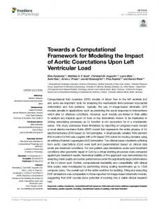
in Listing 3. The fault-injection campaigns are structured in three blocks: A fault configuration with fault sets, faults and locations. The fault configuration may include one or more fault sets. Each fault set specifies a name, fault mode (transient or permanent), a triggering instant, a duration if the mode is transient, and references to one or more faults. Each fault specifies a unique id, a name, a fault effect from the fault-libraries introduced in Section IV and several attributes depending on the effect of the fault. The unique id is automatically set by the GUI in order to avoid duplicates. In the last block, the locations must define a unique id, which is also given by the GUI, and the hierarchical location of the component where the fault has to be injected. In the case of faults from the PIM library, since they are related to signals, the name of the entity to be sabotaged and its port type (input or output) also need to be specified. Both the test-case and fault campaign files are given to the PS-TTM ATE during the initialization phase of the simulation. In this case, the designed test-case simulates a journey of 240 seconds between two stations at a distance of over 7.5 kilometers. We verify the PIM and PSM against 9 and 7 different fault-injection campaigns respectively. The simulations are executed using a quad-core laptop running at 2.60 GHz, with Windows 7 SP1 operating system. The simulations of the PIM take between 1.01 and 1.18 seconds, whereas the PSM needs among 6.19 and 6.72 seconds. The simulation traces do not show any violation of the time determinism property, and the behavior of the railway signaling system is considered satisfactory as all the faults have been detected or masked as expected. As an example, figure 5 shows an extract of the results recorded by the PS-TTM ATE with the test-case and fault configuration presented in listings 2 and 3. Small speed and distance measurement errors caused by the fault can be identified in the figure (up to 0.09m/s and 0.20m respectively). The errors are always within the safety margins, and the detection
vm evm
0.20 0.15 0.10 0.05 0.00 0.05 0.10 0.15 0.20
Error (m/s)
Speed (m/s)
70 60 50 40 30 20 10 00
50
100
Time (s)
150
200
8000 7000 6000 5000 4000 3000 2000 1000 00
sm esm
0.4 0.2 0.0
Error (m)
Traveled Distance (m)
(a) Speed estimation (vm ) and error introduced by fault (evm )
0.2 0.4 50
100
Time (s)
150
200
(b) Traveled distance estimation (sm ) and error introduced by fault (esm )
Fig. 5: Influence of encoder fault in odometric estimations of a balise at the 96th second of the simulation resets the error acumulated during the distance estimation, as expected. VII. C ONCLUSION The design of safety-critical embedded systems is a difficult task, since they must not only satisfy hard real-time requirements but they must also be tolerant to faults. Hard real-time constraints are usually guaranteed by deploying time-triggered functionalities onto time deterministic platforms, such as the TTA. However, the design of safety-critical systems is still a complicated task due to their increasing complexity. Therefore, this paper presented the Platform Specific TimeTriggered Model (PS-TTM), a SystemC based framework to model time-triggered safety-critical embedded systems following the Y-chart approach. Relying on the Y-chart paradigm simplifies the design of such systems by separating the design of the functionality and the platform of the systems. The complexity of the systems is also tackled by applying abstraction, partition and segmentation to the models. The PS-TTM provides a time and value deterministic simulation environment based on the LET and time-triggered MoCs. This enables an early functional and temporal assessment of the systems, whereas eases their deployment onto TTA based platforms. The framework integrates the PS-TTM ATE, a time-triggered automatic test executor that enables nonintrusive simulated fault injection in the PIMs and PSMs for an early assessment of the dependability, what reduces the risk of late and expensive discovery of safety related design flaws. This time-triggered ATE shares the global time with the models, what guarantees the reproducibility of the tests and SFI experiments. ACKNOWLEDGMENT This research work has been partly supported by the European FP7 DREAMS project (grant No. 610640) and the INNPACTO project VALMOD (grant No. IPT-2011-1149370000).
R EFERENCES [1] F. Balarin, M. Chiodo, P. Giusto, H. Hsieh, A. Jurecska, L. Lavagno, C. Passerone, A. Sangiovanni-Vincentelli, E. Sentovich, K. Suzuki, and B. Tabbara, Hardware-software co-design of embedded systems: the POLIS approach. Kluwer Academic Publishers, 1997. [2] B. Kienhuis, E. Deprettere, K. Vissers, and P. van der Wolf, “An Approach for Quantitative Analysis of Application-Specific Dataflow Architectures,” in Application-Specific Systems, Architectures and Processors, 1997. Proceedings., IEEE International Conference on, 1997, pp. 338–349. [3] J. Lapalme, B. Theelen, N. Stoimenov, J. Voeten, L. Thiele, and E. M. Aboulhamid, “Y-chart based system design: a discussion on approaches,” in Nouvelles approches pour la conception d’outils CAO pour le domaine des systems embarqu’es, 2009. [4] J. Miller and J. Mukerji, “MDA Guide Version 1.0.1,” p. 62, 2003/06/12 2003. [5] L. Jozwiak, “Quality-driven design in the system-on-a-chip era: Why and how?” Journal of Systems Architecture, vol. 47, no. 34, pp. 201– 224, 2001. [6] H. Kopetz, “The Complexity Challenge in Embedded System Design,” in ISORC. IEEE, 2008, p. 10. [7] IEEE, “IEEE Standard SystemC Language Reference Manual,” p. 441, 2005. [8] Ansys Esterel, “SCADE Suite,” http://www.esterel-technologies.com/ products/scade-suite/, 2014. [9] Object Management Group, “OMG Unified Modeling Language (OMG UML),” 2011 - 08 - 05 2011, version 2.4.1. [10] ——, “OMG Systems Modeling Language (OMG SysML),” 2012 - 06 - 01 2012, version 1.3. [11] SAE Aerospace, “SAE Architecture Analysis and Design Language (AADL),” 2009. [12] C. Buckl, D. Sojer, and A. Knoll, “FTOS: Model-driven development of fault-tolerant automation systems,” in Emerging Technologies and Factory Automation (ETFA), 2010 IEEE Conference on, 2010, pp. 1–8. [13] J. Perez, C. F. Nicolas, R. Obermaisser, and C. El Salloum, “Modeling Time-Triggered Architecture Based Real-Time Systems Using SystemC,” in Forum on specification & Design Languages (FDL) 2010, T. J. Kamierski and A. Morawiec, Eds. 2010: Springer, 2010. [14] C. M. Kirsch and A. Sokolova, “The Logical Execution Time Paradigm,” in Advances in Real-Time Systems. Springer Berlin Heidelberg, 2012, pp. 103–120. [15] H. Kopetz and G. Bauer, “The Time-Triggered Architecture,” in Proceedings of the IEEE, vol. 91, 2003, p. 15. [16] T. A. Henzinger, B. Horowitz, and C. M. Kirsch, “Giotto: A TimeTriggered Language for Embedded Programming,” in Embedded Software, ser. Lecture Notes in Computer Science, T. Henzinger and C. Kirsch, Eds., vol. 2211. Springer Berlin / Heidelberg, 2001, pp. 166–184. [17] H. Kopetz and N. Suri, “Compositional design of RT systems: a conceptual basis for specification of linking interfaces,” in ObjectOriented Real-Time Distributed Computing, 2003. Sixth IEEE International Symposium on, 2003, pp. 51–60. [18] H. Kopetz, R. Obermaisser, C. El Salloum, and B. Huber, “Automotive Software Development for a Multi-Core System-on-a-Chip,” in Software Engineering for Automotive Systems, 2007. ICSE Workshops SEAS ’07. Fourth International Workshop on, 2007, pp. 2–2. [19] I. Ayestaran, C. F. Nicolas, J. Perez, A. Larrucea, and P. Puschner, “A Simulated Fault Injection Framework for Time-Triggered Safety-Critical Embedded Systems,” in The 33rd International Conference on Computer Safety, Reliability and Security (SAFECOMP), 2014. [20] ASAM HIL workgroup, “ASAM AE HIL Programmers Guide,” p. 162, 2009. [21] I. Ayestaran, C. F. Nicolas, J. Perez, and P. Puschner, “Modeling Logical Execution Time Based Safety-Critical Embedded Systems in SystemC,” in 3rd Mediterranean Conference on Embedded Computing (MECO), 2014. [22] MOGENTES, “Fault Models,” MOGENTES, Tech. Rep., 2009/12/29 2009. [23] H. Kopetz, “The Time-Triggered Model of Computation,” In Real Time Systems Symposium, IEEE Computer Society, p. 16, 1998. [24] P. Winter, B. Guiot, and I. U. o. Railways, Compendium on ERTMS: European Rail Traffic Management System. Eurail Press, 2009.