Proceedings of the World Congress on Engineering and Computer Science 2010 Vol I WCECS 2010, October 20-22, 2010, San Francisco, USA
A Novel Statistical Thresholding in Edge Detection Using Laplacian Pyramid and Directional Filter Banks K. Padma Vasavi, N. Udaya Kumar, E. V. Krishna Rao and M. Madhavi Latha Abstract— To achieve good localization and good
detection of edges, a multi scale approach is required along with the direction of location of the edge. In this paper an edge detector is proposed which uses the Laplacian Pyramid for multi scale decomposition and a Directional Filter Bank to extract the direction. Furthermore, a thresholding based on statistical principles is used to validate the eligibility of a pixel to be an edge pixel. The results obtained from the proposed method are compared with the most popular Canny edge detector and are found to be appreciable. The results are also compared in terms of quantitative terms like psnr (dB) and Mean Square Error (MSE). The proposed method is found to performing better than the Canny edge detector both in terms of quantitative and qualitative evaluation. Index Terms—Directional Filter Bank, Edge Detection, Multi scale Decomposition, Mean Square Error, Standardization, psnr, I. INTRODUCTION The process of edge detection is based on the fact that local discontinuities in image luminance from one level to the other are called edges [1]. Many edge detection techniques like the Sobel’s, Prewitt’s, Robert’s and Friechen local gradient masks are available in the image processing literature. Their major drawbacks are high sensitivity to noise and disability of discrimination of edges versus textures. The Canny edge detector not only detects the edges but also tries to connect neighboring edge points into a contour line. Though, it is considered to be fast, reliable, robust and generic its accuracy is not satisfactory [2]. Turgut Aydin et.al considered the problem of directional and multi scale edge detection using m-based wavelets. However, as a result of separable extension from 1-D bases wavelets in higher dimension can only capture very limited directional information. For instance, 2-D wavelets only provide three Manuscript received May 27, 2010 K. Padma Vasavi is with the Department of ECE, Shri Vishnu Engineering College for Women, Bhimavaram, India(phone: 09441414651; e-mail:
[email protected] ). N. Udaya Kumar is with the Department of ECE, SRKR Engineering College, Bhimavaram, India (e-mail:
[email protected] ). Dr. E. V. Krishna Rao is with Shri Mittapally College of Engineering, Guntur, India ( e-mail:
[email protected] ). Dr. M. Madhavi Latha is with the Department of ECE, JNTU College of Engineering, Hyderabad, India (
[email protected] )
ISBN: 978-988-17012-0-6 ISSN: 2078-0958 (Print); ISSN: 2078-0966 (Online)
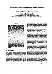
directional components namely horizontal, vertical and diagonal [3]. There have been a number of approaches in providing finer decomposition. Some notable transforms include 2-D Gabor wavelets, the steerable pyramids, the directional filter bank, brushlets, curvelets and contourlets [4]. There are several motivations for employing the directional filter banks. The directional representation implemented by the Directional Filter Bank (DFB) is useful for applications exploiting computational aspects of visual perception [5]. While the DFB can produce directional information, it lacks multi scale feature pr property in contrary to wavelet transform. One way of achieving multi scale decomposition is to combine a Laplacian Pyramid with DFB [6]. In comparison to the other compact representation techniques such as wavelet and sub band coding, the Laplacian Pyramid (LP) has the advantage that it provides greater freedom in designing the decimation and interpolation filters [7]. Thresholding plays an important role in the edge detection of images. This is justified because errors at this point are propagated throughout the detection system. Therefore, to obtain a robust thresholding measure, is a major problem in image segmentation. Thresholding is of two types namely Global and local Thresholding. In global thresholding, one threshold value is selected for the entire image, which is computed from the global information. However, global thresholding results in a poorer segmentation of the image when the illumination of the background is uneven. Therefore, there is a need for a local threshold value that changes dynamically over the image and this technique is called local Thresholding. [8]. In this paper a novel edge detection scheme which uses a statistical thresholding based on the sub band decomposition of images with Laplacian Pyramid at an appropriate scale and a Directional Filter Bank to provide directional information is proposed. The rest of the paper is organized as follows: Section 2 deals with the Laplacian Pyramid Decomposition. Section 3 discusses the Directional Filter Banks. Section 4 provides the information of the statistical thresholding scheme. In section 5 the details of the methodology are furnished. In section 6 experimental procedure and the results obtained are presented. In section 7 the conclusion of the paper is provided. II. LAPLACIAN PYRAMID The Laplacian Pyramid structure was proposed by Burt and Adelson [9].The Laplacian pyramid decomposition is shown in Fig 1. Here, 1-D signals are considered for the sake of WCECS 2010
Proceedings of the World Congress on Engineering and Computer Science 2010 Vol I WCECS 2010, October 20-22, 2010, San Francisco, USA
convenience in the notation. Initially, the input signal x is passed through the decimation filter h to obtain the low pass filtered signal. Then it is down sampled to obtain the coarse signal c1. This coarse signal is up sampled and the filtered using an interpolation filter g. This produces a prediction signal p1. The first level of the detailed signal is given by the prediction error d1. The process is repeated on the coarse signal till the final resolution is reached.
Fig 1. Laplacian Pyramid Decomposition Considering an input signal of N samples, the coarse and detail signals can be derived as c=Hx (1) d=x – GC (2) = (IN –GH) x Where, IN denotes identity matrix of order N and H and G denote the decimation and interpolation matrices which have the following structure ........................... ....h 2 h 1h 0 .... (3) H= ........................... ............................
............................................ ....g 0 g 1g 2 ...................... G= ............g 0 g 1g 2 ............... ..............................................
(4)
(5)
Fig 2 Standard reconstruction structure for LP III.
DIRECTIONAL FILTER BANK
The Directional Filter Bank partitions the frequency plane in to a set of wedge shaped pass band regions as shown in Fig 3 [10]. ISBN: 978-988-17012-0-6 ISSN: 2078-0958 (Print); ISSN: 2078-0966 (Online)
H 0 Z0 , Z1
H1 Z0 , Z1
Z0 2N Z01 βZ0 Z11
(6)
2
Z0 2N-1 Z01βZ0 Z1 βZ0 Z11H0 Z0 , Z1 (7)
Where, β (z0, z1) is a 1-D low pass filter. As the low pass information spreads in to multiple directional sub bands sparse image representation cannot be obtained using DFB. Therefore, a Laplacian pyramid is combined with the DFB so as not to leave any potential characteristic features in an image. IV. STATISTICL THRESHOLDING
Here, the superscript T denotes the matrix transpose operation. If the coarse signal has resolution K then the matrices H and G are of dimension KXN and NXK respectively. Given an LP representation, the standard reconstruction method builds the original signal simply by iteratively interpolating the coarse signal and adding the detail signals at each level up to the final resolution. The standard reconstruction method is shown in Fig 2 Considering an LP with only one level of decomposition the original signal can be reconstructed as
x = Gc + d
Fig 3 Directional Filter Bank frequency partitioning The multi directional analysis is achieved by using a tree structure implementation. Each stage in the tree consists of a two band filter bank that splits the image in to two sub band images by two complementary filters. Using a quincunx 1 1 lattice, i.e., the down sampling matrix equals to , the 1 1 low pass and the band pass filters are given by
In this section, initially the partial derivatives of the image along the horizontal and vertical and vertical directions are determined. Then, a non maximal suppression algorithm interpolates the magnitude of gradients at hypothetical pixels that lie along the direction perpendicular to the edge direction at pixel (x, y) in a 3 x 3 neighborhood around it. If the magnitude of the gradient at (x, y) is not a maximum value among the interpolated magnitudes then it is declared as a non edge point and is suppressed. In order to authenticate a pixel to be an edge pixel, the variations in the neighborhood of the pixel also need to be incorporated. Also, the choice of a threshold varies from image to image as the variations in the gray levels of the neighborhood of the pixel vary from image to image. Therefore, the gradient magnitudes should be standardized using statistic principles to identify a pixel to be an edge pixel. The variation in the gradient magnitude is determined using its variance – covariance matrix given by
σ11 x, y σ12 x, y x, y σ12 x, y σ 22 x, y
(8)
Where, σ11 x, y
2
1 x i im1 nj1 f x x, y 2ππm h 2 h
(9) WCECS 2010
Proceedings of the World Congress on Engineering and Computer Science 2010 Vol I WCECS 2010, October 20-22, 2010, San Francisco, USA
Where, S (x, y) denotes the standardized gradient magnitude at pixel (x, y). The value of S (x, y) is determined for each pixel and if its value is found to be sufficiently large then the pixel (x, y) is considered to be an edge pixel.
A. ALGORITHM 1. Decompose the image in to low pass and Band Pass sub images using Laplacian Pyramids to get multi scale resolution. 2. Apply the Directional Filter Bank to get the directional sub band images. 3. for each sub band i. obtain the partial derivatives along horizontal; and vertical directions. ii. Estimate the variance and covariance matrices using equations (8) - (11) iii. Determine the standardization parameter using equation (12). iv. Obtain the edge map using statistical thresholding. 4. Integrate the edge maps of all the sub bands to get the final edge map. 5. Estimate the performance of the edge detector using equations (13) - (15)
V. DETAILS OF THE METHODOLOGY
VI. EXPERIMENTS AND RESULTS
Most edge detection algorithms specify a spatial scale at which the edges are detected. Typically, edge detectors utilize local operators and the effective area of these local operators defines this spatial scale. At the small scales corresponding to finer image details, edge detectors find intensity jumps in small neighborhoods. At the small scale, some of these edge responses originate from noise or clutter within the image and these edges are clearly not desirable. More interesting edges are the ones that also exist at larger scales corresponding to coarser image details. When the scale is increased, most noise clutter is eliminated in the detected edges but as a side effect the edges at larger scales are not as well localized as the edges at smaller scales. To achieve good localization and good detection of edges, a multi scale approach is needed. Therefore, multi scale decomposition is achieved in this paper, by applying a Laplacian pyramid. Then the directional information is extracted by means of applying the directional filter banks. Also, whether a pixel is an edge pixel or not depends on the gray values of the pixel and the surrounding pixels. After estimating the gradient vector, one should not use the magnitudes of the derivatives alone for determining the eligibility of a pixel to be an edge pixel, though it has been done in that way with many edge detectors. The variations in the neighborhood of a pixel need to be incorporated in this analysis. Threshold values from image to image may vary since the variations in the gray values in the neighborhood of pixels may vary from image to image. In order to automatically vary the threshold standardization of gradient magnitudes is to be done relative to the surrounding pixels gradient magnitude, and then it is to be tested whether the obtained value is large or not. A natural way of doing such standardization in any process is to use appropriate statistical principles. A way of accomplishing the above objective is dealt in our methodology. Our method of standardizing the gradient strength at each pixel locally before thresholding results in the removal of the ambiguity, and thereby produces reliable, robust and smooth edges. For each directional sub band, the statistical thresholding scheme mentioned in section 4 is adapted to extract the edges along each direction. Then all the edge maps at each directional sub band are integrated to get the final edge map.
In this paper, the proposed method has been tested with various images like the lemons image, Bird Image and the flower image. The images were chosen in such a way that the proposed method can be tested for its robustness to detect different types of edges like step edges, roof edges and curved edges for real world images. The proposed technique is applied on the all the images that are mentioned earlier and the resulting edge maps are shown in the Figures 4 -6. The results are then compared with the Canny Edge detector. Canny edge detector is chosen because it is more admired as a most favorable edge detector characterized by its good localization of edges and minimal response. Initially, the flower image shown in Fig 4 is considered for experimentation. The proposed algorithm is tested by taking a ‘Meyer’ Laplacian Pyramidal wavelet and the ‘meyerh2’, ‘5/3’, ‘9/7’ directional filter banks. The edge maps obtained by using the proposed method are presented in Fig 4 (b) – (d) and Fig 4(h-j) respectively. The edge maps obtained by using the Canny edge detector are offered in Fig 4 (e) – (g) and Fig 4 (k)-(m)respectively. The edge maps reveal the fact that the curves and the internal linings of the petals, the stigma of the flower and the other two flowers in the background could predominantly be recognized by using the proposed technique. While, the Canny edge detector could not recognize the petals in the back ground and the internal linings of the petal as well. Moreover, the contour line is not as smooth as the curve lines of the proposed method.
σ 22 x, y
2
1 y j im1 nj1 f y x, y 2ππm h 2 h
(10) 2
2
1 x i y j m n f x x, y f y x, y 2 i 1 j1 2ππm h h h (11) Where fx(x, y) and fy(x, y) are the partial derivatives of the image f(x, y) along the horizontal and vertical directions respectively. Then the standardization parameter S(x, y) for each pixel is defined as σ12 x, y
S (x, y) = f x f y Σ 1 x, y f x f y
T
ISBN: 978-988-17012-0-6 ISSN: 2078-0958 (Print); ISSN: 2078-0966 (Online)
(12)
Fig 4(a) Flower Image (b) meyerh2 (c) 5-3 (d) 9-7 Proposed Method (“Meyer” Laplacian Pyramid)
(e) meyerh2 (f) 5-3 (g) 9-7 Canny’s Method (“Meyer” Laplacian Pyramid)
WCECS 2010
Proceedings of the World Congress on Engineering and Computer Science 2010 Vol I WCECS 2010, October 20-22, 2010, San Francisco, USA
beak are clearly figured in the contour maps of the proposed technique.
(h) meyerh2 (i) 5-3 (j) 9-7 Proposed Method (“db4” Laplacian Pyramid) Fig 6(a) Bird Image (b) meyerh2 (c) 5-3 (d) 9-7 Proposed Method (“Meyer” Laplacian Pyramid)
(k) meyerh2 (l) 5-3 (m) 9-7 Canny’s Method (“db4” Laplacian Pyramid)
Now, the “lemons” image shown in Fig 5 (a) is considered. From the edge shown in Fig 5(b)-(m) the following observations are made. The line distinguishing the outer and inner layers of the lemon skin is identified by the edge maps of the proposed method. Furthermore, the boundaries of the buildings embedded in the top right and bottom left lemons are also recognized by this method. The circle at the center of bottom right lemon and the lines extending from it are clearly identified by the proposed method. The boundaries obtained by the Cannyl method are not clear and could not identify any of the aforementioned details.
(e) meyerh2 (f) 5-3 (g) 9-7 Canny’s Method (“Meyer” Laplacian Pyramid)
(h) meyerh2 (i) 5-3 (j) 9-7 Proposed Method (“db4” Laplacian Pyramid)
(k) meyerh2
Fig 5 (a) Lemons Image (b) meyerh2 (c) 5-3 (d) 9-7 Proposed Method (“Meyer” Laplacian Pyramid
(e) meyerh2
(f) 5-3
(g) 9-7
Canny’s Method (“Meyer” Laplacian Pyramid)
(h) meyerh2 (i) 5-3 (j) 9-7 Proposed Method (“db4” Laplacian Pyramid)
(l) 5-3
(m) 9-7
(k) meyerh2 (l) 5-3 (m) 9-7 Canny’s Method (“db4” Laplacian Pyramid)
The performance of an edge detector can be made in two different methods: the subjective and the objective methods. Subjective methods of performance evaluation of edge detectors use human judgment to estimate the performance of edge detectors. Alternatively, objective methods use signal to noise ratio and mean square error between the edge detectors image and the original one to determine the performance of edge detectors. Even though the objective methods are extensively used, they need not necessarily be associated with our discernment of image quality. For illustration, an image with a low error as determined by an objective measure may actually look much worse than an image with a high error metric [11]. Commonly used objective measures are the root-mean-square error, erms, the root-mean square signal-to-noise ratio, SNRrms, and the peak signal-to-noise ratio, SNRpeak as in equations (13) to (15)
1 M 1 N 1 2 E x, y Ox, y x 0 y 0 MN
e rms
(13)
1 N 1 M x 0 y 0 E x, y
2
(k) meyerh2
(l) 5-3
(m) 9-7
Canny’s Method (“db4” Laplacian Pyramid)
Then, the bird image is taken in to consideration for experimentation. As is in the previous images, the internal lines of the bird’s feathers are majorly identified using the proposed algorithm. Also, the linear edges like the bird’s ISBN: 978-988-17012-0-6 ISSN: 2078-0958 (Print); ISSN: 2078-0966 (Online)
SNR rms
M 1
(14)
1 N y 0 E x, y O x, y
2
x 0
SNR peak 10 log10
L 12 1 M 1 N 1 2 x 0 y 0 E x, y Ox, y MN
(15)
WCECS 2010
Proceedings of the World Congress on Engineering and Computer Science 2010 Vol I WCECS 2010, October 20-22, 2010, San Francisco, USA
Where O(x, y) is the original image, E(x, y) is the reconstructed image and L is the number of gray level equal to 256. From the comparison table it is observed that the proposed method is exhibiting a good improvement in terms of reduction in Mean Square Error by a range of 0.02 to 0.04 and an increase in the psnr value by a range of 0.04 dB to 0.08 dB, when compared to the Canny’s edge detector. VII. CONCLUSION A novel statistical thresholding in edge detection scheme, using the Laplacian Pyramids and directional filter bank is proposed. The results of the proposed algorithm are compared with the Canny’s algorithm exposed to Laplacian pyramid and directional filter banks. From the edge maps obtained using both the algorithms, it can be concluded that the proposed edge detection scheme is performing remarkably well as it is able to identify the in depth edges, curved edges, and linear edges more efficiently than the Canny edge detector REFERENCES [1]
William. K. Pratt “Digital Image Processing”, Wiley Inter Science Publications,3rd Edition 2002.
[2]
Turgut Aydin, Yucel Yemez, emin anarim, Bulent Sankur, “Multi directional and multi scale edge detection via m-band wavelet transform”, IEEE trans.on Image Processing, Vol 5, No, Sept 1996. [3] Minh N Do, “The Finite Ridge let Transform for Image Representation”, IEEE trans.on Image Processing, Vol 12, No1,Jan 2003. [4] Yue Lu, Minh N Do, “A Directional Extension for Multidirectional Wavelet Transforms” [5] ]Trong T Nguyen, Soontorn Oriantara, “A Class of Multi Resolution Directional Filter Banks”, IEEE trans on Signal Processing Vol 55, No3, Mar 2007. [6] W Y Chan, N F Law, W C Siu, “ Multi Scale Feature Analysis using Directional Filter Banks”, IC ICS-PCM , Singapore,2003. [7] Gagan Rath, Christine Guillemot, “Representing Laplacian Pyramids with varying Amount of Redundancy”, EUSIPCO 2006, Italy,2006 [8] Peter J Burt, Edward H Adelson, “ The Laplacian Pyramid as a Compact Image Code”, IEEE Trans on Communications,pp 532-540, vol.Com-31, No3, april 1983. [9] Minh N Do, martin Vetterli, “Pyramidal Directional filter Banks and Curvelts”, ICIP 2001, Greece [10] K. Padma Vasavi, N. Udaya Kumar, E V Krishna rao, M. Madhavi Latha, “ An Adaptive Statistical Thresholding using GLCM in Wavelet Domain”, IRACE Hyderabad, 2008. [11] Mohamed Roushdy, “Comparative Study of Edge Detection Algorithms Applying on the Grayscale Noisy Image Using Morphological Filter”, GVIP Journal, Volume 6, Issue 4, December, 2006
TABLE-I Comparison of psnr(dB) and Mean Square Error S. No
Image
Laplacian Pyramid
DFB Used
Proposed
Canny
Proposed
Meyerh2
0.2112
0.1488
27.4424
28.2020
5-3
0.2163
0.1655
27.3905
27.9718
9-7
0.2077
27.4787
28.2809
Meyerh2
0.1952
0.1347
27.6128
28.4188
5-3
0.2016
0.1291
27.5434
28.5113
9-7
0.1888
0.1260
27.6850
28.5640
Meyerh2
0.4820
0.3390
25.6501
26.4142
5-3
0.4890
0.4012
25.6187
26.0486
9-7
0.4741
0.3383
25.6859
26.4191
Meyerh2
0.4646
0.2866
25.7299
26.7790
5-3
0.4589
0.2973
25.7569
26.6996
9-7
0.4569
0.2904
25.7661
26.7507
Meyerh2
0.1438
0.1051
28.2763
28.9574
5-3
0.1455
0.1221
28.2510
28.6312
9-7
0.1433
0.1044
28.2836
28.9712
Meyerh2
0.1298
0.0896
28.4984
29.3044
5-3
0.1398
0.0942
28.3379
29.1950
9-7
0.1371
0.0911
28.3804
29.2682
Flower meyer
Db4 2
Lemons meyer
Db4 3
Bird
psnr(dB)
Canny
db4 1
Mean Square Error
meyer
ISBN: 978-988-17012-0-6 ISSN: 2078-0958 (Print); ISSN: 2078-0966 (Online)
0.1435
WCECS 2010