Center for Geometric Computing. Department of ... Keywords: graph drawing, grid drawing, planar graph, layout, parallel algo- rithms .... We call such polygons.
Parallel Processing Letters
c World Scienti c Publishing Company
A Parallel Algorithm for Planar Orthogonal Grid Drawings ROBERTO TAMASSIA Center for Geometric Computing Department of Computer Science, Brown University Providence, R.I. 02912{1910, U.S.A.
and IOANNIS G. TOLLIS Computer Science Department, University of Texas at Dallas Richardson, TX 75083, U.S.A.
and JEFFREY SCOTT VITTER� Center for Geometric Computing Department of Computer Science, Duke University Durham, N.C. 27708{0129, U.S.A.
Received December 22, 1997 Revised June 15, 2000 Communicated by Michel Cosnard ABSTRACT
In this paper we consider the problem of constructing planar orthogonal grid drawings (or more simply, layouts ) of graphs, with the goal of minimizing the number of bends along the edges. We present optimal parallel algorithms that construct graph layouts with ( ) maximum edge length, ( 2 ) area, and at most 2 + 4 bends (for biconnected graphs) and 2 4 + 2 bends (for simply connected graphs). All three of these quality measures for the layouts are optimal in the worst case for biconnected graphs. The algorithm runs on a CREW PRAM in (log ) time with log processors, thus achieving optimal time and processor utilization. Applications include VLSI layout, graph drawing, and wireless communication. O n
O n
n
: n
O
n
n=
n
Keywords: graph drawing, grid drawing, planar graph, layout, parallel algorithms, parallel processing
1 Overview The problem of producing automated drawings of graphs has several important applications in the areas of circuit layout and data presentation [5]. In this paper we consider planar orthogonal grid drawings. By \planar," we mean that the � Part
of the work was done while the author was at Brown University.
1
drawing lies in the plane with no crossing edges. \Orthogonal" means that each edge in the drawing is a polygonal chain consisting of alternating horizontal and vertical segments. \Grid" means that the vertices and the bends of the edges have integer coordinates. Such drawings, which we shall refer to simply as layouts, have numerous applications in VLSI and graphics. In VLSI and graphic applications, the main quality measures for a layout that we want to minimize are its area, edge length, and number of bends. Minimizing the number of bends has applications to readability and aesthetics, to communication by light or microwave, and to transportation problems. The problems of minimizing the area and total edge length in layouts are NP-complete [6,9]. In contrast, layouts with a minimum number of bends can be constructed in polynomial time [10]. In recent work [14], we have shown several lower bounds on the number of bends required in layouts. In this paper, we consider the problem of constructing optimal layouts in parallel. We present an optimal parallel algorithm that constructs a layout of an n-vertex graph in O(log n) time using a CREW PRAM with n= log n processors. The layout has O(n) maximum edge length, O(n2 ) area, and at most 2n + 4 bends if the graph is biconnected and at most 2:4n + 2 bends otherwise. This is optimal in the worst case for biconnected graphs. Previously, Aggarwal et al. [1] considered a variation of grid embeddings, called rake embeddings, and showed an algorithm that constructs rake embeddings with O(n2 ) area and at most six bends per edge. The parallel algorithm follows the general scheme of [12], which consists of two phases: orthogonalization and compaction. The orthogonalization phase determines the \shape" of the layout, that is, the angles formed by the edges and bends. The compaction phase assigns grid coordinates to the vertices and bends. In previous work, Tamassia and Vitter [15] parallelized a simpler version of the technique of [12] that avoids compaction and produces layouts having at most 6n bends. We present a novel approach to the compaction phase, based on the concept of \symbolic decomposition" of a rectilinear polygon whose shape is xed but whose geometry (vertex coordinates) is not fully speci ed a priori. Previous compaction algorithms were inherently sequential [8,10,16]. Parallelizing the compaction of a layout was left as an interesting open problem [8]. An earlier and abbreviated version of our work appears in [13].
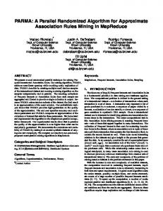
2 Layouts An orthogonal drawing of a graph is a drawing in which each edge is represented by a polygonal chain consisting of alternating horizontal and vertical segments, as shown in Figure 1. A graph has an orthogonal drawing if and only if its maximum vertex degree is 4. Orthogonal drawings are used often in circuit schematics and software engineering diagrams. A drawing is planar if no two edges intersect. A drawing is a grid drawing if the vertices and the bends have integer coordinates. The topology of a planar orthogonal drawing is described by its embedding, which gives for each vertex the sequence of its incident edges arranged in counterclockwise order according to the drawing. We assume that the embedding is speci ed along 2
Fig. 1: A planar orthogonal drawing with eight bends.
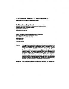
with the graph and that the drawing has to preserve the embedding. Given an embedded planar graph G, a layout for G is a planar orthogonal grid drawing of G that preserves the embedding. There are two types of angles in layouts: those formed at the vertices by consecutive incident edges (in the counterclockwise order), and those formed by the segments that represent individual edges. An orthogonal representation of a graph is a symbolic description of the shape of the layout, in which the orientation of each angle is speci ed but the locations of the vertices and bends are not given. Let , be a layout of a graph G and C an oriented closed simple curve drawn onto ,. Curve C de nes an elementary transformation of , if at each intersection of C with ,, the angle , on the side that C enters from is 180 or 270 degrees. The elementary transformation is performed by bending G by ,90 degrees at each place where C crosses G, as illustrated in Figure 2. An elementary transformation that passes through a bend in an edge causes the bend to be removed, and an elementary transformation that passes through a straight segment of an edge causes a bend to be introduced.
3 Parallel Construction of Layouts Our main result is an optimal parallel algorithm, called GraphLayout , that constructs high-quality layouts of n-vertex biconnected graphs and multigraphs. We discuss later how to extend the algorithm to handle graphs that are not biconnected. The algorithm, which we give below, consists of several transformations, beginning in Step 1 with the construction of the \visibility representation." A visibility representation , for a planar graph G maps every vertex v of G to a horizontal segment ,(v) and every edge (v; u) to a vertical segment ,(v; u) that has its endpoints on ,(v) and ,(u) and does not intersect any other horizontal segment. The visibility representation of the biconnected graph in Figure 3(a) is given in Figure 3(b). The construction of the visibility representation in Step 1 can be done in O(log n) time by an EREW PRAM with n= log n processors [15]. In the process, the edges can be oriented from bottom to top, giving a directed graph on G. 3
C (a)
(b)
Fig. 2: An elementary transformation, de ned by the closed curve C on left. The resulting layout has two fewer bends.
Algorithm GraphLayout f Layout of a biconnected planar graph G with n vertices in the grid. g 1. Construct a visibility representation for G. (See Figures 3(a) and (b).) 2. Transform the visibility representation for G into a preliminary orthogonal embedding , by substituting a grid point for each vertex segment and appropriately changing its connections with the incident edges. (See Figure 3(c).) 3. Let H be the orthogonal representation for ,. Apply successively the three local elementary transformations described in [12] to reduce the number of bends in H . (See Figure 3(d).) 4. From the orthogonal representation H , construct a layout using the compaction algorithm described below. (See Figure 3(e).) We can easily convert a visibility representation into an orthogonal representation in Step 2 by replacing horizontal segments by vertices and vertical segments by edges with bends. Many of the bends that are introduced are subsequently eliminated in Step 3. For example there is an an elementary transformation T that reduces the number of bends on edges that have both left and right bends, as shown in Figure 2, where the number of bends in edge e is reduced from 2 to 1. It is important to note that T is local in nature and can be implemented easily in parallel. The three types of local elementary transformations given in [12] su�ce to achieve a worst-case optimal number of bends. The elementary transformations in Steps 2 and 3 require only local computations and can be done in constant time using one processor per vertex/edge. In the directed version, the direction that each edge emanates from a vertex can be maintained by local updates. The hard part of algorithm GraphLayout is Step 4, in which the orthogonal representation H is embedded without introducing any new bends. Step 4 is the most di�cult to parallelize and is discussed in the remainder of this section. 4
(a)
(b)
(d)
(c)
(e)
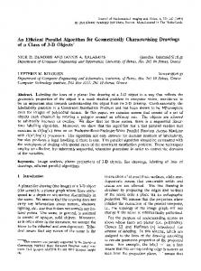
Fig. 3: (a) A biconnected graph G. (b) Visibility representation for G. (c) Orthogonal embedding obtained from (b) by local substitutions. (d) Orthogonal representation of the embedding in (c) obtained after the bend-reducing transformations. (e) Final layout obtained by compaction of the constraints obtained from (d).
Our approach for Step 4 is to \parse" the optimal orthogonal representation H in order to construct the nal layout. We rst break up the orthogonal representation H into its individual polygonal faces. At each vertex v in H , we form all possible pairs of edges (e1 ; e2 ), where e1 and e2 are consecutive in the counterclockwise ordering of v's incident edges. By parallel list ranking on these edge pairs [3], we get the ordered cycle of edges associated with each polygonal face. Each face of H is a rectilinear polygon P for which only the angles are speci ed, 5
e14 e15 e8 e0≡e16 e1 e2 e4
e7
e3
e9 e10
e13
e11 e12
e5 e6
ei e0 e1 e2 e3 e4 e5 e6 e7 e8 e9 e10 e11 e12 e13 e14 e15 e16 turn(i) − − + − + + + − − − + + + + + + − rot(i) 0 −1 −2 −1 −2 −1 0 1 0 −1 −2 −1 0 1 2 3 4
Fig. 4: The rectangles formed from the polygon P by SymbolicDecomposition .
while the coordinates of the vertices are left undetermined. We call such polygons symbolic polygons. The construction of a layout from the orthogonal representation can be viewed as the process of assigning coordinates to a collection of symbolic polygons (the faces of H ) that share vertices and edges. The goal is to make the resulting layout relatively compact. To construct the layout, we generate an appropriate set of embedding constraints, which we later process in a global manner to compute the actual coordinates of the layout. We generate the constraints by individually processing the symbolic polygons of H . For the moment, let us consider only the symbolic polygons that form the interior faces of H ; we describe later how to process H 's exterior face. For each internal face P , we apply the subroutine SymbolicDecomposition to decompose P into a set of symbolic rectangles (as shown in Figure 4). Algorithm SymbolicDecomposition f Symbolic decomposition of an internal orthogonal polygon P into rectangles g 1. The edges of P are oriented in a counterclockwise orientation, that is, given any directed edge, the polygon P lies to its left. 2. For each i, set turn (i) := +1 if e and e +1 form a left turn, and otherwise set turn (i) := ,1 if e and e +1 form a right turn. P 3. For each i, computePthe pre x sums rot (i) := ,=01 turn (j ). (Note that the total sum of turns turn (j ) over all edges in P must be equal to +4, since P is an interior face of H .) 4. For each i, nd the rst edge e going in a counterclockwise direction from e such that rot (j ) = rot (i) + 1, and set front (i) := j . 5. For each i such that turn (i) = ,1, make a \cut" by extending edge e until i
i
i
i
i j
j
j
i
i
6
it touches edge e ( ) . If front (i) = front (k) = j , then the cuts extending e and e touch the same edge e ; in this case the contact point of e is made to follow the one of e along e if and only if e precedes e going in a counterclockwise direction from e . Lemma 1 The cuts computed by algorithm SymbolicDecomposition induce a consistent decomposition of the interior symbolic polygon P into symbolic rectangles. Proof. We show that no two cuts intersect and that each cut partitions a polygon P into two subpolygons P 0 and P 00 with rot (P 0 ) = rot (P 00 ) = 4 An inductive argument can then applied to construct a drawing of P with the given decomposition. Suppose, for purposes of obtaining a contradiction, that the cuts extending edges e and e intersect. Without loss of generality, assume that e is directed rightward, and e is directed downward (see Figure 5), so that rot (i) = rot (j ) + 1. By connectivity arguments, it follows that e precedes e ( ) going in a counterclockwise direction from e . This contradicts the de nition of front (j ), since rot (i) = rot (front (j )). Let us consider the two subpolygons created by a cut. Without loss of generality, we can assume that the edge forming the cut is e0 . Let i = front (0). For the polygon P 0 to the right of the cut, we have rot (P 0 ) = rot (i)+2+1. Since rot (i) = 1, we have rot (P 0 ) = 4. A similar argument shows that rot (P 00 ) = 4. 2 Lemma 2 Algorithm SymbolicDecomposition decomposes an m-vertex interior symbolic polygon P into symbolic rectangles in O(log m) time on a CREW PRAM with m= log m processors. Proof. Step 1 of SymbolicDecomposition can be done in the desired time and processor bounds using an optimal list ranking algorithm [3]. Step 2 takes constant time, given the list ranking of edges. Step 3 involves a parallel pre x computation, front i
i
k
j
k
i
j
i
k
j
i
j
i
j
i
front j
j
ej
efront(i)
ei
efront(j)
Fig. 5: The cuts at edges ei and ej cannot intersect.
7
e14
e13
Fig. 6: The rectangles formed from the external face P. The edges extended are e14 and e13 .
which can be done in the desired time and processor bounds [4]. In Step 4, we make use of the subroutine described in [2] for nding the \nextlarger" of each element of a list. In a list of numbers, the next-larger of a given element x is de ned to be the rst element following x in the list that has a value larger than x's value. We run the next-larger algorithm on the array rot . In Step 5, we need to nd the \next-equal" of each element in the array rot for which turn (i) = ,1, which is simply the next-larger of the (i + 1)st element. The subroutine for nding next-largers is the only part of the algorithm that uses the power of the CREW PRAM instead of the weaker EREW PRAM. 2 The external face of H can be re ned by essentially transforming it into internal faces as follows: We add a bounding rectangle around the external face and traverse the external face so that the external face is to the left during the traversal. Consider some three consecutive outside edges e +1 , e , e ,1 that form two consecutive righthand turns. We project e +1 and e onto the sides of the rectangle. This operation transforms the external face into two internal faces, as shown in Figure 6; one is a rectangle, and the other can be decomposed into rectangles using algorithm SymbolicDecomposition. In order to compute the coordinates of an actual layout, we process the horizontal and vertical adjacency edge constraints (or cuts) that we constructed in Steps 4 and 5 of SymbolicDecomposition for the interior faces (and that we constructed in a similar way for the exterior faces). First let us consider the horizontal constraints. We can make the horizontal constraints more explicit by representing them as a planar st-graph, which is a planar acyclic directed graph with one source s and one sink t, both on the external face. We represent each maximal group of vertically connected vertices in the collection of symbolic rectangles as a single node; each group can be found via list ranking. We put a directed edge from node a to node b if there is a directed horizontal rectangle edge between a vertex represented by a and a vertex represented by b. We add dummy nodes for s and t if there are more than one source or sink. We can topologically sort the nodes of the planar st-graph i
i
i
i
8
i
in time O(log n) time using n= log n processors on an EREW PRAM [15]. The resulting total order gives the x-locations of of the nal layout: For each node a, we assign to all the vertices in the vertical group represented by node a the x-location given by the index of a in the total ordering. We can determine the y-locations for the vertices in the layout in a similar way. In particular, we group together maximal groups of horizontally connected vertices and form the corresponding planar st-graph, where the edges represent vertical cuts. The rest of the construction proceeds symmetrically. Since each vertex has x and y coordinates in the set f1, 2, 3,. . . , ng, the resulting layout has area O(n2 ). The algorithm is of the same type introduced in [12], so the bounds proved there for number of bends and maximum edge length carry forward to our case. The total running time is O(log n) using n= log n processors on a CREW PRAM. Our result is summarized in the following theorem: Theorem 1 For an n-vertex biconnected graph, the algorithm GraphLayout constructs a layout having O(n) maximum edge length, O(n2 ) area, and at most 2n + 4 bends. It runs in time O(log n) on a CREW PRAM with n= log n processors. If the graph G is not biconnected, but rather is only simply connected, we modify Step 1 of Algorithm GraphLayout as follows: We decompose the input graph G into its biconnected components, which can be done optimally in parallel [4,7]. We then construct a visibility representation of G by merging suitably constructed visibility representations of the biconnected components of G using the technique in [12,11], which can be easily parallelized. We obtain the following theorem, where the bound on bends follows from the argument in [12]. Theorem 2 A layout of an n-vertex simply connected graph can be constructed having O(n) maximum edge length, O(n2 ) area, and at most 2:4n +2 bends. It runs in time O(log n) on a CREW PRAM with n= log n processors.
4 Conclusions We have shown how to produce planar orthogonal grid drawings that are optimal in the worst case in terms of the parallel time and processor utilization and in terms of the number of bends produced in the drawing. Our algorithm uses the subroutine in [2] for nding next-smallers, which is designed for a CREW PRAM. We expect that this subroutine can be modi ed to run in the same time and processor bounds on an EREW PRAM, by use of appropriate pipelining techniques. With such an improvement, our planar orthogonal grid drawing algorithm would run with the same time and processor bounds as before but on an EREW PRAM.
Acknowledgements Support for Prof. Tamassia was provided in part by by the O�ce of Naval Research and the Defense Advanced Research Projects Agency under contract N00014{91{ J{4052, ARPA order 8225, and by a research grant from Cadre Technologies, Inc. Support for Prof. Tollis was provided in part by the Texas Advanced Research 9
Program under Grant No. 3972. Support for Prof. Vitter was provided in part by National Science Foundation grants CCR{9007851 and CCR{9522047, and by the O�ce of Naval Research and the Defense Advanced Research Projects Agency under contract N00014{91{J{4052, ARPA order 8225.
References
1. A. Aggarwal, M. Klawe, D. Lichtenstein, N. Linial, and A. Wigderson. Multi-layer grid embeddings. In Proc. 26th Annu. IEEE Sympos. Found. Comput. Sci., 186{196, 1985. 2. O. Berkman, D. Breslauer, Z. Galil, B. Schieber, and U. Vishkin. Highly parallelizable problems. In Proc. 21st ACM Symp. on Theory of Computing, 309{319, 1989. 3. R. Cole and U. Vishkin. Approximate parallel scheduling, part i: the basic technique with applications to optimal parallel list ranking in logarithmic time. SIAM J. Comput., 17(1), 128{142, 1988. 4. R. Cole and U. Vishkin. Approximate parallel scheduling. II. applications to logarithmic-time optimal parallel graph algorithms. Information and Computation, 92, 1{47, 1991. 5. G. Di Battista, P. Eades, R. Tamassia, and I. G. Tollis. Algorithms for drawing graphs: an annotated bibliography. Comput. Geom. Theory Appl., 4, 235{282, 1994. 6. D. Dolev, F. T. Leighton, and H. Trickey. Planar embedding of planar graphs. In F. P. Preparata, editor, Advances in Computing Research, volume 2, 147{161. JAI Press, Greenwich, Conn., 1985. 7. H. Gazit. Optimal EREW parallel algorithms for connectivity, ear decomposition, and -numbering of planar graphs. Manuscript, Duke University, 1990. 8. F. Ho�mann and K. Kriegel. Embedding rectilinear graphs in linear time. Information Processing Letters, 29, 75{79, 1988. 9. J. A. Storer. On minimal node-cost planar embeddings. Networks, 14, 181{212, 1984. 10. R. Tamassia. On embedding a graph in the grid with the minimum number of bends. SIAM J. Comput., 16(3), 421{444, 1987. 11. R. Tamassia and I. Tollis. A provably good linear algorithm for embedding graphs in the rectilinear grid. Technical Report Technical Report ACT-64, Coordinated Science Lab, University of Illinois, December 1985. 12. R. Tamassia and I. G. Tollis. Planar grid embedding in linear time. IEEE Trans. on Circuits and Systems, CAS-36(9), 1230{1234, 1989. 13. R. Tamassia, I. G. Tollis, and J. S. Vitter. Lower bounds and parallel algorithms for planar orthogonal grid drawings. In Proc. IEEE Symposium on Parallel and Distributed Processing, 386{393, 1991. 14. R. Tamassia, I. G. Tollis, and J. S. Vitter. Lower bounds for planar orthogonal drawings of graphs. Inform. Process. Lett., 39, 35{40, 1991. 15. R. Tamassia and J. S. Vitter. Parallel transitive closure and point location in planar structures. SIAM J. Comput., 20(4), 708{725, 1991. 16. G. Vijayan and A. Wigderson. Rectilinear graphs and their embeddings. SIAM J. Comput., 14, 355{372, 1985. st
10