A Particular Multi-Agent Framework for Execution of Application and Resource Management Alexandru Cicortas, Victoria Iordan Computer Science Department Faculty of Mathematics and Computer Science University of the West Timisoara e-mail:
[email protected],
[email protected]
Abstract: Complex applications execution needs a lot of conditions starting with hardware and software resources thru the task sequencing and verifying the results of the execution. The needed resources can be found locally or on the Web and Grid. For an efficient usage the needed resources application and the effective resources found must be described in an appropriate and way and we propose the XML. The matching between the resources of the application and the Web/Grid resources is done in our proposal by the agents. Keywords: multi-agent systems, grid, resource management, complex systems design
1
Introduction
Real world systems grow in complexity. The execution of complex applications implies adequate tools and also support for execution. The Web and Grid offer an efficient way for executing the requirements of companies that must interact in a very complex manner. The grid model, with its use of resources tends to be heterogeneous and distributed across multiple management domains. For example, in a grid environment shared resources must remain accessible, not but that the hardware configuration is dynamic, the resources can be available in a time instant, but in an another time instant these can disappear. In the grid key infrastructure services must be available, and virtual organizations must be maintained. It must also be possible to detect report and deal with faults that may occur in any of the member domains. Effective system management is only possible if resources are manageable, and if tools are available to manage them. However, these tools tend to operate independently and to use proprietary interfaces and protocols to manage a limited set of resources, making it difficult for an organization to build an efficient, well-
integrated management system. In order to allow the development of manageability standards that will enable conforming management tools to manage conforming resources in a uniform manner, and to interoperate with each other. In turn this will enable system administrators to choose their management tools and suppliers in the knowledge that, regardless of their origin, the tools can work cooperatively in an integrated management environment. As stated in [11] the resource management includes: • reservation, brokering and scheduling; • installation, deployment and provisioning; • metering; • aggregation (service groups, WSDM collections, etc.); • VO management; • security management; • monitoring (performance, availability, etc.); • control (start, stop, etc.); • problem determination and fault management. Some of other major problems are to use and discovery the resources. The problem of execution of complex applications that must be solved in an efficient manner using the grid requires a lot of complex tools. Some of aspects of the problem concern: • formulating the problem that is proposed to be solved; • expressing an adequate decomposition of the application in the tasks; • for every task to express the hardware and software resources that are needed; • giving an appropriate expression of the task sequencing and conditioning; • searching and discovering on the grid for the appropriate resources and services; • if there is the case to allow the migration of the software agents (SA) on the grid and also to install these SA (the adequate software); • defining the data that must be partially hosted for the future tasks (temporary storage of partial data or needed data for recovering in the case of failure); • defining the recoveries when some failure occurs. The execution of such grid application can be expressed in terms of workflow. This subject will be detailed in another paper. Concerning the workflow of the complex application on the grid, there are many works like [3], [12].
There exist a lot of works that threat partially or totally such a kind of approach in the grid context. The GLOBUS [7] UNICORE [14] and the works done for the Fraunhofer Resource Grid [6] solve in some partially sense the above requirements. Being in many cases a complex problem the jobs execution needs to overcome some of the exception situations as rollbacks and resuming in the incidents. In a framework it implies some additional activities like: • localization of the failed task; • analysis of the task execution; • the resuming of the task from an intermediary point if there exists a such point; • resuming the data bases implied in the same node or other nodes. There exist many frameworks that allow to the application designers to dispose for: • tools, standards and languages to define express and use the information concerning the evolution of the application during its execution; • an adequate Grid framework that allows to: o explore and find the grid resources; o establish in the grid context, the conditions for the task execution and in the failure cases the conditions for resuming the task(like the temporary storage of data); o launching and controlling the task execution; o in order to obtain the desired results the framework must allow the rollbacks. We propose also a particular such framework. Multi-agent systems are used in many domains and their strength allows developing complex systems. The agent abilities i.e., self adaptation, learning from own experience or from collectivity experience, the communication and collaboration are very expressive tools in order to reach the system goals. The following concepts [16] are closely related: • Choreography describes required patterns of interaction among services and templates for sequences (or more structures) of interactions; • Orchestration describes the ways in which business processes are constructed from Web services and other business processes, and how these processes interact;
• Workflow is a pattern of business process interaction, not necessarily corresponding to a fixed set of business processes. All such interactions may be between services residing within a single data center or across a range of different platforms and implementations anywhere. The XML is used for expressing the appropriate information that can be processed using various platforms in most recent initiatives concerning the usage of adequate standards that are applied in many domains. In many of real projects the XML [18] is an adequate mean in order to allow expressing the needs and it in platform independent. Based on the previous experience in the following the XML will be used. The paper proposes: • a framework that uses the XML that allows to express and furnish the required information to the designer. The information concerns the grid its resources, its services, its location and also the details of the application concerning its decomposition in tasks, the sequencing of the tasks and consequently the resources and services needed for tasks execution; • a multi-agent system as a solution for solving such kind of problems; • a workflow model for the execution of the applications in the grid context. It will be the subject of another work and papers due the particularities of the workflow. The paper is structured as follows. The information used is shortly revised in the next Section. The third Section presents the concepts and tools used for modeling. The fourth Section, propose the multi-agent system as a possible solution. In Section 5 the framework is sketched and some details are given. The last Section contains some conclusions and future works.
2
The Information
Some of the resource Grid components usually are not described in the necessary detailed form in order that its description can be efficient used, i.e., all its attributes that specify if the resource or service can be used by certain service or software. For overtaking it we must define a function that allows to the user to receive the desired and detailed hardware resource attributes. The resources are basically hardware resources and software resources. The hardware resource is characterized by: • the resource type; • the resource name, in some cases can be used an ID(entifier); • the resource location;
• a set of its attributes; • a set of its components; we can define in turn a structured resource. The software resource is characterized by: • the resource type; • the resource name, in some cases can be used an ID(entifier); • the needed support that is composed by a set of hardware resources every being quoted with appropriate attributes. The information concerning the authorization, access and security is not detailed here in order to simplify the presentation. The information that describes the hardware resource, software resource and the services, given as XML files, furnished by the grid will be processed in an appropriate way by the specific tools in order to fulfill the system requirements. In order to find the node where a task can be executed, a matching between the resource node in formation and the resource needed for the software resource (of the task) will be done. For a detailed resource description, we propose the following resouseSchema:
We illustrate with the following resouseExample: Windows Xp 46546 10.10.10.10 255.0.0.0 1 INTEL /dev/c NTFS 500 512 256 128 400
afarcas /bin/bash /home/anca ok 10 anca runnig 10000 listeaza directorul curent
3
The Concepts and Tools used in Modeling
A complex application is composed from a set of tasks that generally must interact and that must be processed (executed) in a specified sequencing order. For its execution every task needs a set of specified resources. The resources are specific and every resource has particular properties. In order to define a complete specification for a resource we will use some conventions from [8] that will be extended. In many other grid projects are used various means for describing the dynamic behavior of complex grid applications. These means consist from coupled software components and appropriate data. The data is used for: • mapping the grid application onto the underlying grid middleware; • controlling the workflow and data flow of the grid application.
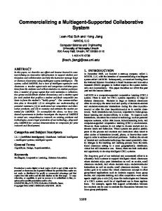
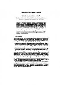
Based on the previous, we need tools that allow describing: • resources of the grid; • basic resources that are required to define the grid job; • the model of the grid job workflow using various concepts like Directed Acyclic Graphs (DAG) [14] or Petri nets derivatives [1], [13]. Directed Acyclic Graphs (Fig. 1) are widely spread due their structure but they have some disadvantages like: being directed it is impossible to define bidirectional coupling schemes, it is also impossible to define loops. The DAGs describe only the behavior but not the state of the system. The Petri nets can be used to control the workflow of complex applications [1]. Details concerning Petri nets and their properties can be found in [13]. The models for workflow that use Petri nets can be found in papers of van der Aalst [1]. In Fig. 2 is given an example of Petri net that is equivalent to the DAG from the Fig. 1. Parent P child Q R P
Parent Q R child S
Q
R
S Figure 1 Example of a Directed Acyclic Graph (DAG)
Q
P
S
R
Figure 2 Example of a Petri Net equivalent to the DAG in Fig. 1
The Petri nets can be used for modeling the workflow and also to control the workflow of complex applications. In many cases the workflow within grid applications can be equivalent to the data flow. That means that the decision when a software component can be launched in execution depends upon the availability of the input data. As a consequence the tokens in the Petri net represent real data that is exchanged between the software components in the grid. So, the Petri net can be used to model the interaction between software components in the grid represented by software transitions and data resources represented by data places. In order to control the workflow due to the fact that in some cases the workflow is independent from the data flow is necessary to introduce control transitions and control places. In this case the tokens (that represent the process state) need some additional information that is the color of the token so the colored Petri nets [9]. The Petri nets used for modeling the workflow must have some particular properties that can be seen in [1]. These properties are: • the net has one input location and one output location; • the initial marking is that contains only one token in the input location; • the final marking contains only one token in the output location; • from any marking (state) between the initial marking and final marking there is a path to the final marking; • by placing one transition that has an input arc form the output location and an output arc to the input location the Petri net is safe. A formal verification of the modeled system can be used and it is based of the Petri net properties. This verification can be easy done and expressed in a mathematical form. Basic features that can be expressed like: conflict confusion, contact, trap, deadlock are well-defined properties of Petri nets that can be very useful during of the process of optimization of the workflow of a complex grid application. We do not enter into the details concerning the features that can be given for express in Petri nets terms of the execution in parallel, sequential execution, definitions of the conditions or loops. There exist many approaches to describe Petri nets with XML-based language, e.g., the Petri Net Markup Language (PNML) [10]. Recently, UML activity diagrams [17] have been used for workflow modeling. There exist some approaches [5] that use the UML’s activity diagrams those was added some especially semantic in order to improve a better utility in workflow modeling. The ebXML [4] is used to model e-business services. In the ebXML the event features of activity diagrams are used quite extensively: events being the standard means of communication between different business partners.
4
The Multi-agent System as a Solution
Due of the complexity of problems around the development of grid applications an adequate and efficient solution can be developed using the agents that act in a multi-agent system. The agents must be designed in order to fulfill their own goals and also the system goals. The agents must cooperate and concur in order to obtain the needed resources. In many approaches is used the negotiation. Negotiation between intelligent agents is one of the basic issues in Distributed Artificial Intelligence and Multi-Agent Systems [2]. A negotiation process tends to modify the own plan of each agent in order to achieve agreement among a subset of agents in the system. One of the main works in this area Contract Net Protocol (CNP) [15] serves as a basis for a lot of variants that are already frequently used. The CNP was initially developed for decentralized task allocation and is a distributed negotiation model based on the notion of call for bids on markets. The relation between clients (managers, customers, buyers) and suppliers (bidders, contractors, sellers) is created in a call for bids and evaluation of the proposals submitted by the bidders to the managers. This CNP has several limits: As a multi-agent system is distributed, several managers can concurrently call for bids, so an agent may have to manage several negotiation processes in parallel in order to reduce the length of its negotiation processes. Some of the applications of the CNP force the contractors to sequence their negotiation processes, i.e., to answer with a single bid at a time. Sequencing the processing of contractor answers to the calls emitted by the various managers may make the contractors miss some contracts. When the multi-agent system is equipped with delay failure detectors, it may also force the managers to consider these contractor agents as failures. CNP-based applications enable the agent to break its commitments when the agent receives an offer for a better task in comparison with those for which the agent is committed. However breaking the commitments is not always a good solution because it makes managers call again for bids to find anew contractors for their tasks.
5
The Proposed Framework
In [8] is proposed a very complex model that uses a Grid Application Definition Language (GADL). It contains a set of XML-based description languages in order to define and assemble complex grid applications for mapping these applications onto the available hardware and software resources and to control the workflow during the execution. The GADL is composed from description languages for resources, interfaces data and jobs. Based on these the user interfaces with by Task mapping, grid job builder and Grid job handler.
The proposed framework is basically a multi-agent system (MAS), where the agents execute appropriate actions in order to improve their goals and also the general objective: the execution of the application (job) on the grid. In the following, for specific actions are proposed agents that can play different roles. The Descriptive and Analyzer Agent (DAA): • describes: -
the grid and its resources and services these can be posted on a portal and given as an appropriate response to the user for a requirement;
-
interacting with the user it decomposes the application (the job) in the tasks and relieves their dependencies.
The results of these descriptions consist in appropriate files stored in data base. • analyzes the grid status updating the files that describe the grid; • tries to verify the application (job) structure in some fashion. In Figure 3 the Descriptive Analyzer Agent working on the application presented by the user generates the decomposition of it in tasks and their sequencing. The Grid resources are usually posted on a portal. USER 1 Application
1 1 -tasks -tasks sequencing
2 DAA
grid resources 2
GRID Figure 3 The Descriptive Analyzer Agent. The trace marked with 1 generates the application decomposition and the trace marked with 2 generates the grid resource description.
The complex application executed on the grid (and not only) imposes a strong analysis concerning: • its decomposition in tasks with the specification of the resources that are needed during the task execution; • the tasks sequencing and where the case is the tasks correlation. It is a major challenge the tasks parallelization during their execution; • the failures and erroneous task execution that imposes: -
the rescheduling or reminded tasks for execution in the new contest;
-
the temporary data storage imposed by the failure;
-
the supplementary services that are required for replying the rest of the tasks execution.
Concerning the execution, a task in characterized by: • its identifier; • the preconditioning of the task execution; • the post conditioning (that is unleashed by its execution); • the needed resources and their amount. All these are given in XML files. The sequencing can be done in some ways, one of these being based on Colored Petri Nets .In this paper it is done in a simplified way using Place/Transition Petri Nets. Using such a representation we are able expressing the: • concurrency (the parallelism) and • synchronization between tasks (and tasks sequences). In the following we present some of the possibilities that illustrate the modeling of the application execution. In the first one is represented the data flow. Tokens in the places are the data and the transitions are the tasks. The application execution in time is given by tokens flow in the net. Also a tool that manages the Petri net that manages the application execution is needed. The Petri nets used are timed Petri nets. In the Figure 4 the data flow and the tokens in the places represent data and the transitions are the tasks execution. Here the sequence of tasks t 2 ,t 4 and the sequence t 3 ,t 5 can be executed concurrent (in parallel). The task t 6 is synchronization (instant transition). The initial marking of Petri net is (1,0,0,0,0,0,0,0,0,0) i.e., the start of the application. This marking enables [13] the transition (the task t1 ) that fires
and based on the Petri net rules the transitions t 2 and
t3 are enabled and also
these transitions can fire. p2
t2
p4
t4
p6 t6 p8
t1
p1
p9
t7
p10
p3
p5 t3
p7 t5 Figure 4
The Petri Net for an application
A major lack of workflow models is that the case instantiation is treated in isolation. In real life that is not true. The major problem concerns to the resources their contention and sharing (these are not treated by workflow models). Based on an analysis done we propose that the following features to be used: • the time must be taken into consideration, i.e., all the activities evolve in time (the workflow also); • as an intuitive representation we can imagine that every workflow of an application is represented in a plane and the application are represented in parallel planes; • the resources that are available in the grid and are used in the application execution are situated between these planes. As an explanation we propose the following. Somewhere a resource is used by a task of an application. This resource is unavailable to other tasks because the token that represents the resource in its appropriate place does not exist, being used by the task. When the task execution is finished then the token that represents the resource is placed back into its appropriate place and can be used by another task. The other one possibility, where the resources are represented, can be done in two ways. The first one, given in the Figure 5 the resource that is in the place p is in the total amount #r and the task
t1i needs an amount a1i for its execution that is
acquired when it is available in the location p and when the transition
t1i fires (the
appropriate task is executed) after that this amount is returned back to the location p. The same is the execution of the task represented by the transition t 2 j from the Application 2. t1i Appl1
#a1i
#a1i
p
#r
#a2j
#a2j
Appl2 t2j Figure 5 The first way of the representation of task execution
Another way is given in the Figure 6, where the task execution is represented in a more complicated manner. Here the transition t s represents the start of the task execution and the transition t e represents its end. The time spent by the token into the place between the two transitions t s and t e . So, the transitions t s start the task execution when the resource is available in the desired amount (as in the previous figure) and at the end of the execution, the amount used during the task execution is released and returned to the appropriate place of the resource (denoted by #r).
ts
te
Appl1
taski #a1
#a1
#r #a2
#a2 taskj
Appl2 ts
te Figure 6
The second way of the representation of task execution
The Broker Agent (BA): based on the files that contains the tasks and their attributes, explore the grid and detect: • nodes where exist needed resources; • analyzes if exists the software resources or if these software resources can be installed; • extracts the availabilities of the resources in time when other agents require it. The EXEcutive Agent (EXEA), using the job description and task sequencing planes the proposal for execution and decomposes it onto the grid nodes. Based on the data that give the resource status of the grid in time the BA explores the availabilities decides: • the proposed schedule for the job execution; • the desired nodes in order that it will be able to negotiate for the job tasks. Finally the EXEA submit to the user the planning of the job execution. The user can or not accepts the proposal made and the BA that must renegotiate must take the user decision as a new requirement in the new imposed conditions (of the user). One of the important features proposed in the framework is that the ability to install certain software in a node.
During the execution phase the EXEA receives notifications concerning the evolution of tasks execution. Also another main feature concerns to the capability proposed by the framework for treating the failures and the rollbacks. The Broker Agent negotiates the tasks requirements with the nodes where the required conditions for the task execution exist. It negotiation concern also the time interval that is supposed by the user for task execution and the availabilities of the grid nodes. There can be used an adequate policy that allow to the BA to obtain some advantages in the sense that the required task time intervals to be obtained form the node or other nodes that are available in these time intervals. All the information that is used by the agents consists form appropriate XML documents. Conclusions The grid and its applications is one of the most dynamic and challenging domains. Most of companies and academic organizations are involved in grid and its applications. It is very difficult to develop a complex and complete framework for the execution of applications on the grid due to complexity of problems. The paper intended to propose a framework that is based on a multi-agent system and uses the XML as basis for information that is used in to the framework. References [1]
van der Aalst, W. M. P.: The Applications of Petri Nets to Workflow Management, The Journal of Circuits, Systems and Computers 8, pp. 2166, 1998
[2]
Akine, s., Pinson, S., Shakun, M.: An Extended Multi-Agent Negotiation Protocol, Autonomous Agents and Multi-Agent Systems, Vol. 8(1), pp. 545, 2004
[3]
Brown, J. L, Ferner, C. S., Shipman, W. J: GridNexus and JXPL: A Grid Services Workflow System, http://www.globusworld.org/program/, 2006
[4]
ebXML http://www.ebxml.org, 2003
[5]
Ershuis, R., Wieringa R.: Comparing Petri Net and Activity Diagram Variants for Workflow modeling- A Quest for Reactive Petri Nets, In H. Ehrig, W. Reisig, and G. Rozenberg, editors, Petri Net, Technologies for Communication Based Systems, LNCS, Springer-Verlag, Berlin, pp. 2325354, 2002
[6]
Fraunhofer Resource Grid http://www.fhrg.fhg.de, 2003
[7]
The Globus Project: The Globus Resource Specification Language (RSL v.1.0), http://www.globus.org.gram/rsl_spec1.html, 2000
[8]
Hoheisel, A., Der, U,: AN XML-Based Framework for Loosely Coupled Applications on Grid Environment, P. M. A. Sloot et al. (Eds.), ICCS 2003, LNCS 2657, pp. 245-254, 2003
[9]
Jensen, K.: Colored Petri Nets,Vol1-3 Springer, 1997
[10]
Jungel, M., Kindler, E., Weber, E.: The etri Net Markup Language, Philippi, S., (ed) Workshop Algorithmen und Werkzeuge fur Petri Netze. Univ. Koblenz-Landau, pp. 47-52, 2000
[11]
Maciel, et. al: Resource Management in http://www.ggf.org/documents/GFD.45.pdf, pp. 1-24, 2005
[12]
Kacsuk, P., Dosza, G., Kovacs, J., Lovas, R., Podhorszki, N., Balaton, Z., Gombas, G: P-GRADE: A Grid Programming Environment, J. Grid Comput. Vol. 1, No. 2, pp. 171-197, 2003
[13]
Petri, C. A.: Kommunication mit Automaten, Ph.D. Dissertation, Insitut fur Instrumentale Mathematik, Bonn, 1962
[14]
Romberg, M.: The UNICORE Architecture: Seamless Access to Distributed Resources, Procs of the 8th Intl Symposium on High Performance Distributed Computing (HPDC-8), Los Alamitos, pp. 287293, 1999
[15]
Smith, G. R: The Contract net protocol: High-level communication and control in a distributed problem solver, IEEE Transactions on Computers, Vol. 12, 1980
[16]
Treadwell, J.: Open Grid Services Architecture Glossary of Terms, http://www.ggf.org/documents/GFD.44.pdf, pp. 1-15, 2005
[17]
Introduction to OMG’s UML, http://www.omg.org, 2005
[18]
Walsh, N.: A Technical Introduction http://www.xml.com/pub/a/98/10/guide0.html, 1998
to
OGSA,
XML,