I would like to thank my advisor Dr. Scott DeLoach for the much needed ...... C.Y.J. Chiang, G. Levin, Y.M. Gottlieb, R. Chadha, S. Li, A. Poylisher, S. Newman,.
MASSPEC - MULTIAGENT SYSTEM SPECIFICATION THROUGH POLICY EXPLORATION AND CHECKING by SCOTT J. HARMON B.S., Kansas State University, 2002 M.S., Kansas State University, 2004
AN ABSTRACT OF A DISSERTATION submitted in partial fulfillment of the requirements for the degree DOCTOR OF PHILOSOPHY Department of Computing and Information Sciences College of Engineering KANSAS STATE UNIVERSITY Manhattan, Kansas 2012
Abstract Multiagent systems have been proposed as a way to create reliable, adaptable, and efficient systems. As these systems grow in complexity, configuration, tuning, and design of these systems can become as complex as the problems they claim to solve. As researchers in multiagent systems engineering, we must create the next generation of theories and tools to help tame this growing complexity and take some of the burden off the systems engineer. In this thesis, I propose guidance policies as a way to do just that. I also give a framework for multiagent system design, using the concept of guidance policies to automatically generate a set of constraints based on a set of multiagent system models as well as provide an implementation for generating code that will conform to these constraints. Presenting a formal definition for guidance policies, I show how they can be used in a machine learning context to improve performance of a system and avoid failures. I also give a practical demonstration of converting abstract requirements to concrete system requirements (with respect to a given set of design models).
MASSPEC - MULTIAGENT SYSTEM SPECIFICATION THROUGH POLICY EXPLORATION AND CHECKING by SCOTT J. HARMON B.S., Kansas State University, 2002 M.S., Kansas State University, 2004
A DISSERTATION submitted in partial fulfillment of the requirements for the degree DOCTOR OF PHILOSOPHY Department of Computing and Information Sciences College of Engineering KANSAS STATE UNIVERSITY Manhattan, Kansas 2012
Approved by:
Major Professor Scott A. DeLoach
Copyright Scott J. Harmon 2012
Abstract Multiagent systems have been proposed as a way to create reliable, adaptable, and efficient systems. As these systems grow in complexity, configuration, tuning, and design of these systems can become as complex as the problems they claim to solve. As researchers in multiagent systems engineering, we must create the next generation of theories and tools to help tame this growing complexity and take some of the burden off the systems engineer. In this thesis, I propose guidance policies as a way to do just that. I also give a framework for multiagent system design, using the concept of guidance policies to automatically generate a set of constraints based on a set of multiagent system models as well as provide an implementation for generating code that will conform to these constraints. Presenting a formal definition for guidance policies, I show how they can be used in a machine learning context to improve performance of a system and avoid failures. I also give a practical demonstration of converting abstract requirements to concrete system requirements (with respect to a given set of design models).
Table of Contents Table of Contents
vi
List of Figures
x
List of Tables
xiii
Acknowledgements
xiv
Dedication
xv
Preface 1 Introduction 1.1 Motivation . . . . . . . . 1.2 Thesis Statement . . . . 1.3 Contributions . . . . . . 1.4 Philosophy of Approach 1.5 Overview . . . . . . . . .
xvi
. . . . .
. . . . .
. . . . .
. . . . .
. . . . .
. . . . .
2 Background 2.1 Multiagent Systems . . . . . . . . . 2.1.1 Agents . . . . . . . . . . . . 2.1.2 Agents in Systems . . . . . 2.2 Organization-based MAS . . . . . . 2.2.1 Goals . . . . . . . . . . . . . 2.2.2 Roles . . . . . . . . . . . . . 2.2.3 Protocols . . . . . . . . . . 2.2.4 Policies . . . . . . . . . . . 2.2.5 Ontology . . . . . . . . . . . 2.3 Electronic Institutions . . . . . . . 2.4 OperA . . . . . . . . . . . . . . . . 2.5 MOISE+ . . . . . . . . . . . . . . 2.6 OMACS . . . . . . . . . . . . . . . 2.6.1 Metamodel . . . . . . . . . 2.6.2 Organizational Goal Model . 2.6.3 Capabilities . . . . . . . . . 2.6.4 Agents . . . . . . . . . . . . 2.6.5 Roles . . . . . . . . . . . . .
. . . . .
. . . . . . . . . . . . . . . . . . vi
. . . . .
. . . . . . . . . . . . . . . . . .
. . . . .
. . . . . . . . . . . . . . . . . .
. . . . .
. . . . . . . . . . . . . . . . . .
. . . . .
. . . . . . . . . . . . . . . . . .
. . . . .
. . . . . . . . . . . . . . . . . .
. . . . .
. . . . . . . . . . . . . . . . . .
. . . . .
. . . . . . . . . . . . . . . . . .
. . . . .
. . . . . . . . . . . . . . . . . .
. . . . .
. . . . . . . . . . . . . . . . . .
. . . . .
. . . . . . . . . . . . . . . . . .
. . . . .
. . . . . . . . . . . . . . . . . .
. . . . .
. . . . . . . . . . . . . . . . . .
. . . . .
. . . . . . . . . . . . . . . . . .
. . . . .
. . . . . . . . . . . . . . . . . .
. . . . .
. . . . . . . . . . . . . . . . . .
. . . . .
. . . . . . . . . . . . . . . . . .
. . . . .
. . . . . . . . . . . . . . . . . .
. . . . .
. . . . . . . . . . . . . . . . . .
. . . . .
. . . . . . . . . . . . . . . . . .
. . . . .
. . . . . . . . . . . . . . . . . .
. . . . .
. . . . . . . . . . . . . . . . . .
. . . . .
1 1 2 2 3 3
. . . . . . . . . . . . . . . . . .
5 5 5 6 6 7 7 7 7 7 8 8 9 9 9 10 10 11 11
2.7
Agent Oriented Software Engineering 2.7.1 Gaia . . . . . . . . . . . . . . 2.7.2 ADELFE . . . . . . . . . . . 2.7.3 Prometheus . . . . . . . . . . 2.7.4 Tropos . . . . . . . . . . . . . 2.7.5 O-MaSE . . . . . . . . . . . . 2.8 Policies and Norms . . . . . . . . . . 2.8.1 KAoS . . . . . . . . . . . . . 2.8.2 PONDER . . . . . . . . . . . 2.9 Program Analysis . . . . . . . . . . . 2.9.1 Model Checking . . . . . . . . 2.10 Artificial Intelligence . . . . . . . . . 2.10.1 Machine Learning . . . . . . . 2.10.2 Satisfiability . . . . . . . . . . 2.11 Conclusions . . . . . . . . . . . . . .
. . . . . . . . . . . . . . .
. . . . . . . . . . . . . . .
. . . . . . . . . . . . . . .
. . . . . . . . . . . . . . .
. . . . . . . . . . . . . . .
. . . . . . . . . . . . . . .
. . . . . . . . . . . . . . .
. . . . . . . . . . . . . . .
. . . . . . . . . . . . . . .
. . . . . . . . . . . . . . .
. . . . . . . . . . . . . . .
. . . . . . . . . . . . . . .
. . . . . . . . . . . . . . .
. . . . . . . . . . . . . . .
11 11 12 12 13 14 14 15 16 17 17 18 18 19 20
3 Guidance and Law Policies 3.1 Introduction . . . . . . . . . . . . . . . . . . . . . . . 3.1.1 Contributions . . . . . . . . . . . . . . . . . . 3.1.2 Chapter Outline . . . . . . . . . . . . . . . . . 3.2 Motivating Examples . . . . . . . . . . . . . . . . . . 3.2.1 Conference Management System . . . . . . . . 3.2.2 Cooperative Robotic Floor Cleaning Company 3.3 Multiagent Traces . . . . . . . . . . . . . . . . . . . . 3.3.1 System Traces . . . . . . . . . . . . . . . . . . 3.4 Policies . . . . . . . . . . . . . . . . . . . . . . . . . . 3.4.1 Language for policy analysis . . . . . . . . . . 3.4.2 Law Policies . . . . . . . . . . . . . . . . . . . 3.4.3 Guidance Policies . . . . . . . . . . . . . . . . 3.5 Evaluation . . . . . . . . . . . . . . . . . . . . . . . . 3.5.1 CRFCC . . . . . . . . . . . . . . . . . . . . . 3.5.2 Conference Management System . . . . . . . . 3.5.3 Common Results . . . . . . . . . . . . . . . . 3.6 Conclusions . . . . . . . . . . . . . . . . . . . . . . .
. . . . . . . . . . . . . . . . .
. . . . . . . . . . . . . . . . .
. . . . . . . . . . . . . . . . .
. . . . . . . . . . . . . . . . .
. . . . . . . . . . . . . . . . .
. . . . . . . . . . . . . . . . .
. . . . . . . . . . . . . . . . .
. . . . . . . . . . . . . . . . .
. . . . . . . . . . . . . . . . .
. . . . . . . . . . . . . . . . .
. . . . . . . . . . . . . . . . .
. . . . . . . . . . . . . . . . .
. . . . . . . . . . . . . . . . .
21 21 22 22 22 22 24 28 28 30 31 32 33 37 37 38 42 43
4 Learning Policies to Self-Tune Systems 4.1 Introduction . . . . . . . . . . . . . . . 4.1.1 Contributions . . . . . . . . . . 4.1.2 Chapter Outline . . . . . . . . . 4.2 Self-Tuning Mechanism . . . . . . . . . 4.3 Evaluation . . . . . . . . . . . . . . . . 4.3.1 Conference Management System 4.3.2 Information System . . . . . . .
. . . . . . .
. . . . . . .
. . . . . . .
. . . . . . .
. . . . . . .
. . . . . . .
. . . . . . .
. . . . . . .
. . . . . . .
. . . . . . .
. . . . . . .
. . . . . . .
. . . . . . .
45 45 46 46 47 54 55 58
vii
. . . . . . . . . . . . . . .
. . . . . . . . . . . . . . .
. . . . . . .
. . . . . . . . . . . . . . .
. . . . . . .
. . . . . . . . . . . . . . .
. . . . . . .
. . . . . . . . . . . . . . .
. . . . . . .
. . . . . . . . . . . . . . .
. . . . . . .
. . . . . . . . . . . . . . .
. . . . . . .
. . . . . . . . . . . . . . .
. . . . . . .
. . . . . . .
. . . . .
. . . . .
. . . . .
. . . . .
. . . . .
. . . . .
. . . . .
. . . . .
. . . . .
. . . . .
. . . . .
. . . . .
. . . . .
. . . . .
. . . . .
. . . . .
. . . . .
. . . . .
. . . . .
5 Abstract Quality driven Policy Generation 5.1 Introduction . . . . . . . . . . . . . . . . . . 5.1.1 Contributions . . . . . . . . . . . . . 5.1.2 Chapter Outline . . . . . . . . . . . . 5.2 Quality Metrics . . . . . . . . . . . . . . . . 5.2.1 System Traces . . . . . . . . . . . . . 5.2.2 Efficiency . . . . . . . . . . . . . . . 5.2.3 Quality of Product . . . . . . . . . . 5.2.4 Reliability . . . . . . . . . . . . . . . 5.3 Policy Generation . . . . . . . . . . . . . . . 5.4 Conflict Discovery . . . . . . . . . . . . . . . 5.5 Conflict Analysis . . . . . . . . . . . . . . . 5.6 Evaluation . . . . . . . . . . . . . . . . . . . 5.6.1 CRFCC . . . . . . . . . . . . . . . . 5.6.2 IED Detection System . . . . . . . . 5.6.3 Information System . . . . . . . . . . 5.6.4 Conference Management System . . . 5.7 Related Work . . . . . . . . . . . . . . . . . 5.8 Conclusions . . . . . . . . . . . . . . . . . .
. . . . . . . . . . . . . . . . . .
. . . . . . . . . . . . . . . . . .
. . . . . . . . . . . . . . . . . .
. . . . . . . . . . . . . . . . . .
. . . . . . . . . . . . . . . . . .
. . . . . . . . . . . . . . . . . .
. . . . . . . . . . . . . . . . . .
. . . . . . . . . . . . . . . . . .
. . . . . . . . . . . . . . . . . .
. . . . . . . . . . . . . . . . . .
. . . . . . . . . . . . . . . . . .
. . . . . . . . . . . . . . . . . .
. . . . . . . . . . . . . . . . . .
. . . . . . . . . . . . . . . . . .
. . . . . . . . . . . . . . . . . .
. . . . . . . . . . . . . . . . . .
. . . . . . . . . . . . . . . . . .
74 . 74 . 75 . 75 . 75 . 76 . 78 . 81 . 82 . 83 . 86 . 87 . 88 . 88 . 91 . 94 . 95 . 102 . 102
. . . . . . . . .
. . . . . . . . .
104 104 105 105 105 106 108 109 111 115
. . . .
116 116 117 118 119
4.4 4.5 4.6
4.3.3 IED Detection System 4.3.4 Common Results . . . Limitations . . . . . . . . . . Related Work . . . . . . . . . Conclusions . . . . . . . . . .
. . . . .
. . . . .
. . . . .
. . . . .
. . . . .
. . . . .
. . . . .
6 Using Unsatisfiable-Core Analysis to Explore 6.1 Introduction . . . . . . . . . . . . . . . . . . . 6.1.1 Contributions . . . . . . . . . . . . . . 6.1.2 Chapter Outline . . . . . . . . . . . . . 6.2 Conflict UNSAT-Core Analysis . . . . . . . . 6.2.1 Policy Synthesis and Analysis . . . . . 6.3 Resolution Strategies . . . . . . . . . . . . . . 6.4 CRFCC System Evaluation . . . . . . . . . . 6.4.1 CRFCC Results . . . . . . . . . . . . . 6.5 Conclusions . . . . . . . . . . . . . . . . . . . 7 Conclusions 7.1 Guidance and Law Policies 7.2 Learning Policies . . . . . 7.3 Abstract Qualities . . . . 7.4 Soft-Goal Conflicts . . . .
. . . .
. . . .
. . . .
. . . .
. . . .
. . . .
viii
. . . .
. . . .
. . . .
. . . .
. . . .
Soft-Goal Conflicts . . . . . . . . . . . . . . . . . . . . . . . . . . . . . . . . . . . . . . . . . . . . . . . . . . . . . . . . . . . . . . . . . . . . . . . . . . . . . . . . . . . . . . . . . . . . . . . . . . . . . . . . . . . . . . . . . . . . .
. . . .
. . . .
. . . .
. . . .
. . . .
. . . .
. . . .
. . . .
. . . .
. . . .
. . . .
. . . .
. . . .
. . . . . . . . .
. . . .
. . . . . . . . .
. . . .
. . . .
62 68 69 71 72
Bibliography
120
A Policy Format 132 A.1 XML Schema . . . . . . . . . . . . . . . . . . . . . . . . . . . . . . . . . . . 132 B Object Models B.1 Base Classes . . . B.2 Policy Learning . B.3 Trace Generation B.4 Conflict Analysis B.5 Simulation . . . .
. . . . .
. . . . .
. . . . .
. . . . .
. . . . .
. . . . .
. . . . .
. . . . .
. . . . .
. . . . .
. . . . .
. . . . .
. . . . .
. . . . .
. . . . .
. . . . .
C Information Flow Specification and Checking C.1 Introduction . . . . . . . . . . . . . . . . . . . C.2 Background . . . . . . . . . . . . . . . . . . . C.2.1 Security in multiagent systems . . . . . C.3 Policies in O-MaSE . . . . . . . . . . . . . . . C.4 Medical Billing System . . . . . . . . . . . . . C.5 Security Policies . . . . . . . . . . . . . . . . . C.5.1 Access Control Policies . . . . . . . . . C.5.2 Information Flow Policies . . . . . . . C.6 Security policy reasoning . . . . . . . . . . . . C.6.1 Reasoning example . . . . . . . . . . . C.6.2 Automating Security Policy Reasoning C.7 Conclusions . . . . . . . . . . . . . . . . . . . C.8 Limitations . . . . . . . . . . . . . . . . . . .
ix
. . . . .
. . . . . . . . . . . . .
. . . . .
. . . . . . . . . . . . .
. . . . .
. . . . . . . . . . . . .
. . . . .
. . . . . . . . . . . . .
. . . . .
. . . . . . . . . . . . .
. . . . .
. . . . . . . . . . . . .
. . . . .
. . . . . . . . . . . . .
. . . . .
. . . . . . . . . . . . .
. . . . .
. . . . . . . . . . . . .
. . . . .
. . . . . . . . . . . . .
. . . . .
. . . . . . . . . . . . .
. . . . .
. . . . . . . . . . . . .
. . . . .
. . . . . . . . . . . . .
. . . . .
. . . . . . . . . . . . .
. . . . .
. . . . . . . . . . . . .
. . . . .
. . . . . . . . . . . . .
. . . . .
133 133 134 134 136 136
. . . . . . . . . . . . .
140 140 141 141 143 144 146 146 150 153 154 156 159 160
List of Figures 2.1 2.2
OMACS Metamodel . . . . . . . . . . . . . . . . . . . . . . . . . . . . . . . Q-Learning Grid World . . . . . . . . . . . . . . . . . . . . . . . . . . . . . .
10 19
3.1 3.2 3.3 3.4 3.5 3.6 3.7 3.8 3.9 3.10 3.11
Conference Management Goal Model. . . . . . . . . . . . . . . . . . . . . . . Conference Management Role Model. . . . . . . . . . . . . . . . . . . . . . . CRFCC Goal Model. . . . . . . . . . . . . . . . . . . . . . . . . . . . . . . . CRFCC Role Model. . . . . . . . . . . . . . . . . . . . . . . . . . . . . . . . Events and Properties of Interest. . . . . . . . . . . . . . . . . . . . . . . . . No agent may review more than five papers. . . . . . . . . . . . . . . . . . . Partial orders of Guidance Policies. . . . . . . . . . . . . . . . . . . . . . . . CRFCC Agent model . . . . . . . . . . . . . . . . . . . . . . . . . . . . . . . The success rate of the system given capability failure. . . . . . . . . . . . . The extra vacuum assignments given capability failure. . . . . . . . . . . . . Violations of the guidance policies as the number of papers to review increases.
23 25 26 27 28 32 36 37 39 40 41
4.1 4.2 4.3 4.4 4.5 4.6
48 49 51 53 56
4.7 4.8 4.9 4.10 4.11 4.12 4.13 4.14 4.15
Learning Integration. . . . . . . . . . . . . . . . . . . . . . . . . . . . . . . . State and Action Transition. . . . . . . . . . . . . . . . . . . . . . . . . . . . Ordered and Unordered states and their matching substates. . . . . . . . . . Pseudo-code for generating the policies from the state, action pair sets. . . . Limit Reviewer policy preventing theory papers from being assigned. . . . . Agent goal achievement failures with self-tuning (learning), hand-tuning (optimal), and no tuning. . . . . . . . . . . . . . . . . . . . . . . . . . . . . . . Information System Goal Model. . . . . . . . . . . . . . . . . . . . . . . . . IS Role Model. . . . . . . . . . . . . . . . . . . . . . . . . . . . . . . . . . . Agent failures with no self-tuning. . . . . . . . . . . . . . . . . . . . . . . . . Agent failures using action and substate learning for self-tuning. . . . . . . . Goal Model for IED Detection System. . . . . . . . . . . . . . . . . . . . . . Role Model for IED Detection System. . . . . . . . . . . . . . . . . . . . . . IED Search Area for various Patrollers. . . . . . . . . . . . . . . . . . . . . . IED Scenario 1 Learning Results (log scale). . . . . . . . . . . . . . . . . . . IED Scenario 2 Learning Results (log scale). . . . . . . . . . . . . . . . . . .
5.1 5.2 5.3 5.4 5.5 5.6
Simple example goal model. . Goal only traces. . . . . . . . Simple example role model. . Goal-role traces. . . . . . . . . Simple example agent model. Goal-role-agent traces. . . . .
77 77 78 79 79 80
. . . . . .
. . . . . .
. . . . . .
. . . . . . x
. . . . . .
. . . . . .
. . . . . .
. . . . . .
. . . . . .
. . . . . .
. . . . . .
. . . . . .
. . . . . .
. . . . . .
. . . . . .
. . . . . .
. . . . . .
. . . . . .
. . . . . .
. . . . . .
. . . . . .
. . . . . .
. . . . . .
. . . . . .
. . . . . .
. . . . . .
57 60 61 63 64 66 67 68 69 70
5.7 5.8 5.9 5.10 5.11 5.12 5.13 5.14 5.15 5.16 5.17 5.18 5.19 5.20 5.21 5.22 5.23
Goal Choice & Capability Failure Probabilities . . . . . . . . . . . . . . System Traces to Prefer . . . . . . . . . . . . . . . . . . . . . . . . . . Policy combining algorithm . . . . . . . . . . . . . . . . . . . . . . . . CRFCC Goal Assignment Choice with Capability Failure Probabilities CRFCC Generated Policy . . . . . . . . . . . . . . . . . . . . . . . . . Efficiency Policy Generation Effects on Assignments . . . . . . . . . . . Reliability Policy Generation Effects on Assignments . . . . . . . . . . Quality Policy Generation Effects on Quality of Goal Achievement . . . IED Goal Assignment Choice with Capability Failure Probabilities . . . Reliability Policy Generation Effects on Assignments . . . . . . . . . . Efficiency Policy Generation Effects on Assignments . . . . . . . . . . . Capability Failure Probabilities . . . . . . . . . . . . . . . . . . . . . . CMS Agent Model Augmentation . . . . . . . . . . . . . . . . . . . . . Quality of Product Ordering . . . . . . . . . . . . . . . . . . . . . . . . CMS Efficiency Results (Lower is Better) . . . . . . . . . . . . . . . . . CMS Reliability Results (Lower is Better) . . . . . . . . . . . . . . . . CMS Quality Results (Lower is Better) . . . . . . . . . . . . . . . . . .
. . . . . . . . . . . . . . . . .
. . . . . . . . . . . . . . . . .
. 81 . 84 . 85 . 88 . 89 . 90 . 91 . 92 . 92 . 93 . 94 . 95 . 96 . 97 . 99 . 100 . 101
6.1 6.2 6.3 6.4 6.5 6.6 6.7 6.8 6.9
Abstract requirement analysis process. . . . . . . . . . . CRFCC Generated Policy . . . . . . . . . . . . . . . . . Object to Literal Mapping . . . . . . . . . . . . . . . . . CRFCC Agent Model . . . . . . . . . . . . . . . . . . . . CRFCC Goal Assignment Choice with Capability Failure CRFCC Quality of Product Ordering . . . . . . . . . . . CRFCC Policy Conflicts . . . . . . . . . . . . . . . . . . CRFCC Reliability Results . . . . . . . . . . . . . . . . . CRFCC Quality Results . . . . . . . . . . . . . . . . . .
. . . . . . . . .
. . . . . . . . .
. . . . . . . . .
. . . . . . . . . . . . . . . . . . . . . . . . . . . . . . . . Probabilities . . . . . . . . . . . . . . . . . . . . . . . . . . . . . . . .
106 107 107 110 111 111 111 113 114
A.1 Policy DTD. . . . . . . . . . . . . . . . . . . . . . . . . . . . . . . . . . . . . 132 B.1 B.2 B.3 B.4 B.5 B.6 B.7
Base Policy UML Diagram. . . . Policy Learning UML Diagram. . Policy Trace Base UML Diagram. Policy Trace UML Diagram. . . . Policy Generation UML Diagram. Policy Trace SAT UML Diagram. Core Simulator and Models. . . .
. . . . . . .
. . . . . . .
. . . . . . .
. . . . . . .
. . . . . . .
. . . . . . .
. . . . . . .
. . . . . . .
. . . . . . .
. . . . . . .
. . . . . . .
. . . . . . .
. . . . . . .
. . . . . . .
. . . . . . .
. . . . . . .
. . . . . . .
. . . . . . .
. . . . . . .
. . . . . . .
. . . . . . .
133 134 135 136 137 138 139
C.1 C.2 C.3 C.4 C.5 C.6
Medical Billing System Goal Model. . . . . . Medical Billing System Role Model. . . . . . Price Services Protocol. . . . . . . . . . . . . Medical Billing System Access Matrix. . . . An Access Matrix with a parametrized role. Patient Files resource projected schema. . .
. . . . . .
. . . . . .
. . . . . .
. . . . . .
. . . . . .
. . . . . .
. . . . . .
. . . . . .
. . . . . .
. . . . . .
. . . . . .
. . . . . .
. . . . . .
. . . . . .
. . . . . .
. . . . . .
. . . . . .
. . . . . .
144 145 146 148 148 151
xi
. . . . . . .
. . . . . . .
. . . . . . .
C.7 Accounting Database resource projected schema. . C.8 Operator semantics. . . . . . . . . . . . . . . . . . C.9 Extended operator semantics. . . . . . . . . . . . C.10 Automatic policy verification system architecture. C.11 Checking ‘can r1 access property υ5 ’. . . . . . . .
xii
. . . . .
. . . . .
. . . . .
. . . . .
. . . . .
. . . . .
. . . . .
. . . . .
. . . . .
. . . . .
. . . . .
. . . . .
. . . . .
. . . . .
. . . . .
151 153 154 157 158
List of Tables 3.1
Conference Management Policies. . . . . . . . . . . . . . . . . . . . . . . . .
xiii
34
Acknowledgments I would like to thank my advisor Dr. Scott DeLoach for the much needed encouragement and guidance in the writing of this thesis. His patience and support have been greatly appreciated. I would also like to thank my committee Dr. Robby, Dr. Steve Warren, and Dr. Julie Adams for their suggestions and input during my proposal. A special thanks goes to my family who have had to put up with me being a “perpetual student” and who have supported me during my late nights of research, my weekends of writing, and my conference trips.
xiv
Dedication To my wife Lisa and children Benjamin, Teresa, Julia, Thomas, Katherine, Samuel, Bernadette, and the unnamed.
xv
Preface How do you distill years of work, research, study, and thought into a single document? You cannot. However, in this work, I attempt to give you a window into my adventures. This document serves as a lense into the universe that has been formed by the years of work, research, study, and thought. This lense focuses but on a small sliver. Yet, if you strain, and examine the edges, you can catch a glimpse of the rest of my universe.
xvi
Chapter 1 Introduction Organization-based multiagent systems engineering has been proposed as a way to design complex adaptable systems [1, 2]. Agents interact and can be given tasks depending on their individual capabilities. The agents themselves may exhibit particular properties that were not initially anticipated. As multiagent systems grow, configuration, tuning, and design of these systems can become as complex as the problems they claim to solve.
1.1
Motivation
We have identified several sources of complexity in multiagent design and deployment. The system designer may not have planned for every possible environment within which the system may be deployed. The agents themselves may exhibit particular properties that were not initially anticipated. The system designer is faced with the task of designing a system to not only meet functional requirements, but also non-functional requirements. Conflicts within non-functional requirements should be uncovered and, if necessary, the stakeholders should be consulted to help resolve those conflicts. Current organization-based multiagent system design documents give us a high-level abstraction of the system. This high-level abstraction can be leveraged to automate the analysis of aspects of the system with respect to the system requirements; both concrete and abstract. Abstract requirements (soft-goals) represent qualities rather than products 1
of the system. These qualities can often be in conflict with respect to the system design. These conflicts are usually resolved during implementation and many times in an ad-hoc manner. We bring these decisions back to design-time, before implementation begins. This allows for more realistic expectations by the stakeholders for the final product through the discussion and resolution of these conflicts early within the design process.
1.2
Thesis Statement
Guidance policies offer a useful construction for reasoning with multiagent systems and developing automated tools for aiding in their construction. Specifically, guidance policies help system designers to construct multiagent systems that are adaptable and that satisfy non-functional requirements. In order to make an engineering discipline from the art of multiagent system construction, system designers require mathematically grounded tools. While there has been much work in processing functional or quantitative requirements, non-functional, or qualitative requirements have been lagging. The aim of this research is to push the frontier and help provide some initial groundwork for other researchers to develop theories and tools to support a multiagent system designer with these qualitative concerns.
1.3
Contributions
Policies as formal constraints have been generally difficult to write correctly and difficult to implement correctly. In order to solve this problem, I propose attacking it from two directions. First, in order to write policies more naturally, we must step back and look at the reason for the policy in the first place—that is the abstract qualities that we want our system to have. Second, we must be able to either generate an implementation that conforms to our specified policies or we must be able to test an implementation against the specified policies to ensure that they are implemented correctly. With this approach, we get additional traceability of system requirements into design decisions. 2
I propose a specification framework for multiagent systems, using the concept of guidance policies, to both automatically generate specific constraints for a given set of multiagent system models as well as provide an implementation for generating code that will conform to these constraints. System designers need tools to help them produce specifications and evaluate design decisions early in the design process. The approach we are taking is to first generate a set of system traces using the models created at design time. Second, we analyze these system traces, using additional information provided by the system designer. Third, we compute a set of policies that will guide the system toward the abstract qualities desired. And, fourth, we analyze the computed policies for conflicts.
1.4
Philosophy of Approach
We strongly believe in taking a practical approach in our work. The work should have practical results that can be utilized in the field. Building tools is a very good way to ensure that our research remains practical and useful to people working in this area. We do also believe, however, that the tools and work must be firmly grounded in formal logic. This is the strong foundation that helps ensure correctness and allows us to convince ourselves and others of the properties of our work.
1.5
Overview
The rest of this thesis is organized as follows. In Chapter 2, we present some of the background in multiagent systems, multiagent system engineering, organization-based multiagent systems, and the use of policies in organization-based multiagent systems. Chapter 3 introduces and formalizes the concept of guidance polices. In this chapter we also show the usefulness of guidance policies through experimentation. Next, in Chapter 4, we develop a method to automatically learn guidance policies in order to self-tune organization-based multiagent systems. Chapter 5 presents our offline approach to automatically generating 3
guidance policies that are based on abstract qualities. Chapter 6 looks at conflict resolution for the automatically generated guidance policies.
4
Chapter 2 Background Much work has been done in the area of multiagent systems. Specifically, policies have been examined with respect to these systems. Organizational-based multiagent systems tend to utilize policies in their design and often in their implementation.
2.1
Multiagent Systems
Multiagent systems (MAS) are composed of a group of autonomous agents. In a cooperative environment, they work together to achieve a common purpose or goal. Multiagent systems are expected to be robust, reliable, adaptive, and autonomous. A multiagent system is made up of an environment, E, a set of objects, O, and a group of agents, A. Ferber defines an agent as a physical or virtual entity, which has autonomy[3]. This agent can act in its environment and is driven by some sort of objective. Multiple agents in a system necessarily form organizations. This may have an explicit or implicit structure. Organization-based multiagent systems leverage this organizational structure within system design.
2.1.1
Agents
Agents are a natural extension of object-oriented paradigms. Agents, unlike plain objects, have a life, that is they perform some actions. With this so-called “life”, agents tend to be directed in their actions by some outside goal or events. 5
When we think of agents, we usually think of rational agents. Generally agents are simply machines that perceive and affect the environment. A rational agent, however, is “one that does the right thing” [4]. There are two types of rational agents. The first is purely reactive. These agents do not have autonomy and thus react in some predictable manner to events occurring in their environment. The second type of agent is autonomous. These agents have some notion of the goals that they are pursuing and have a certain freedom to decide how to behave in their environment.
2.1.2
Agents in Systems
Agents within some system generally are performing some function of the system. This function may require autonomous or simply reactive behavior. Because the agent is now part of a larger system, it must communicate and coordinate its actions with the rest of the system. This can be a non-trivial problem. We will later see how organization-based multiagent systems approach this problem by providing some structure to the interactions between agents and other parts of the system.
2.2
Organization-based MAS
Organization-based MAS have been proposed as a way of dealing with coordination, communication, and goals in a general manner without dealing with a specific agent [5]. Concepts from human organizations have been incorporated into this paradigm: Goals, Roles, Protocols, Policies, and Ontologies. Ferber defines a micro-macro relationship in multiagent systems where constraints and social objectives are placed on the agents from the organization and properties emerge from the organization because of the agents’ actions [3].
6
2.2.1
Goals
Goals are objectives. In the simplest terms, a goal is a state that we desire our system to reach. A goal achievement may result in some concrete product, e.g. the achievement of a goal to publish a paper could result in a publication. Other goal achievements may be without a physical product, such as the the achievement of a goal to move from point A to point B. More abstract goals may be to avoid running into obstacles, or to be efficient.
2.2.2
Roles
Roles in the agent paradigm are modeled after roles in sociology. Roles usually come with responsibilities and privileges. They imply a social structure for communication and authority. They may also imply some sort of fitness to perform some action. Roles are often used to capture expected behavior of an agent who is playing a particular role.
2.2.3
Protocols
Protocols outline the details for interactions between agents. Normally, this is to communicate some sort of information. The information communicated may be used to aid in coordination, or simply the result of some request.
2.2.4
Policies
Policies are rules that are imposed on agents by the system designer. These rules may come from different entities (i.e. from within the agent itself, or implied by the role). The rules may be externally enforced by disallowing the forbidden action (or forcing the required one) or the agent may be sanctioned after a violation occurs.
2.2.5
Ontology
Ontologies define the vocabulary of the agents within a system and allow proper communication between agents. An ontology defines the objects and the relationships between them. When constructing policies, we need to represent relevant concepts and physical properties 7
of the environment. The relevant concepts and physical properties are the ones that we need to mention in our Roles, Goals, Protocols, and Policies. Having an ontology allows us to formally define the concepts, terms, and entities used within our policies.
2.3
Electronic Institutions
Electronic Institutions include all the concepts introduced in Organization based MAS, but make these concepts explicit in the environment. The organization is an entity in itself, bringing it’s own goals and norms (policies). Electronic Institutions place more control with the institution than in simple agent organizations. Interactions between agents are typically controlled and the institution insures the system is driven toward achievement of its end.
2.4
OperA
Dignum introduced Organizations per Agents (OperA) in 2004 [6]. OperA describes an organizational framework for multiagent systems. There are three main models in OperA: the Organization model, the Social model, and the Interaction model. The Organization model describes the organization using four structures: the social structure, the interaction structure, the normative structure, and the communicative structure. These may generally be mapped to role structure, plan or goal structure, policy set, and protocols respectively. The Social model depicts an agent’s responsibilities with respect to the organization. That is, it tracks the roles the agents are playing. The interaction model specifies how the various roles interact (what protocols are allowed and how they are used). OperA partitions norms into three sets: Role norms, Scene norms, and Transition norms. Role norms are global norms that apply to a role that an agent may be playing. Scene norms are associated with agents playing roles during an interaction or coordination. Transition norms are enforced when an agent, playing a role, is transitioning from one interaction or scene to another. The norms in OperA are defined manually by the system architect and use the standard, “obligation, permission, and prohibition” categories. They are defined 8
using a set of predicates over the domain variables and functions.
2.5
MOISE+
MOISE+ is an extension of Model of Organization for multI-agent SytEms (MOISE). MOISE+ describes three aspects for multiagent organizations: the structural aspect, the functional aspect, and the deontic aspect [7]. The structural aspect describes agents’ relationships through roles and links. The functional aspect describes plans to achieve various goals. The deontic aspect describes the various policies (obligations and permissions) imposed on the agents. The deontic aspect describes the policies in terms of obligations and permissions of roles that are played by agents. The permission and obligations are defined as a 3-tuple with the role, mission, and time constraint for the policy. A mission is a plan on how to achieve part of a goal of the system. The time constraint may be for all time or may be any time period (continuous or non-continuous). These policies must also be constructed by hand.
2.6
OMACS
Organization Model for Adaptive Computational Systems (OMACS) [1] defines the concepts and relationships between MAS concepts for the organization-based multiagent systems. OMACS is targeted toward the construction of highly adaptive and reliable multiagent systems.
2.6.1
Metamodel
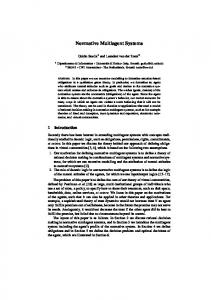
The basic OMACS metamodel is given in Figure 2.1. OMACS defines standard multiagent system entities and their relationships. Agents are capable of playing roles. Roles can achieve goals. Policies constrain the organization. The organization (which is comprised of agents) assigns agents to play various roles in order to achieve specific goals. The organization may make these assignments through a centralized approach (a single agent makes the 9
assignments) or through a distributed approach. Organization
requires
Capabilities
constrains
possesses
Domain Model
uses Goal
achieves
Role
capable
Agent
Policy
Figure 2.1: OMACS Metamodel
2.6.2
Organizational Goal Model
An important feature in both Electronic Institutions and the methodologies used to implement such systems is that of a goal model. The goal model allows for a logical decomposition of the overall goal for a system. Over time various models have been proposed. The Goal Model for Dynamic Systems (GMoDS) [8] is one such model. This goal model is similar to the Tropos goal model [9]. GMoDS allows for such things as AND/OR decomposition of goals, as well as, precedence between goals and triggering of new goal instances (i.e. while trying to achieve a particular goal, an event may cause another goal to become active). Instance goals (triggered goals) may have parameters that specialize them for the task at hand. For example, a Clean goal may be parametrized on the coordinates of the area to clean.
2.6.3
Capabilities
A capability is something possessed by an agent that enables an agent to perform some function. These functions are used to achieve particular goals. In OMACS, agents may have various levels of capabilities, which determines how an agent will perform when using
10
each capability.
2.6.4
Agents
Agents are the entities that do things within the system. They possess capabilities, which they then can use to achieve various goals. Agents may be pursuing any number of goals at any time.
2.6.5
Roles
In OMACS, a role is defined as “a position within an organization whose behavior is expected to achieve a particular goal or set of goals.” [1]. Roles are played by an agent when an agent is pursuing some goal. In human organizations we also have the notion of role. Various positions within a company could be considered different roles one could play within the company. Since a role is used to achieve a goal, roles are related to the goals that they can achieve and to the capabilities that are required to play each role.
2.7
Agent Oriented Software Engineering
From these different types of agent-based systems has sprung methodologies for engineering systems based on these concepts. These methodologies give support to software engineering in building systems using agent-oriented concepts. Agent Oriented Software Engineering (AOSE) brings the science developed in agent technologies to the engineering used in practical systems.
2.7.1
Gaia
A pioneer in AOSE, Gaia [10, 11], introduced many of the concepts used today in many other AOSE methodologies. Gaia uses a series of models to move from requirements to analysis and finally to design phases. The aim of the final design is that it contain sufficient
11
detail to allow implementation of the system, which will properly fulfill the stakeholders’ requirements. Gaia begins with a requirements statement, from there both a role model and an interaction model are constructed. From the role model, an agent model is defined. Finally, from both the role model and the interaction model, a services and an acquaintance model are designed. Organizational rules were introduced into the analysis phase. These organizational rules are basically policies and norms over the organization as a whole. These organizational rules tend to be used to describe liveness or safety properties the system must exhibit.
2.7.2
ADELFE
ADELFE describes a methodology for building adaptive multiagent systems [12]. ADELFE is based on the AMAS Theory [13]: “For any functionally adequate system, there is at least a cooperative interior medium system which fulfills an equivalent function in the same environment”. The AMAS Theory proposes that a system should not be engineered, but rather the system should ‘build itself’ [14]. You provide the system with the desired global behavior and the ability to adapt, and the system will find the best configuration to achieve that global behavior. ADELFE consists of several workflows, moving through requirements, analysis, and design. In the requirements workflow, in addition to the normal requirements gathering, an environment model is constructed. The analysis workflow determines if the requirements can be satisfied adequately using the AMAS theory. In this workflow, agents are identified and interactions are modeled. In the design workflow, detailed descriptions of the agents are constructed using UML notation. Class diagrams of all required components are devised.
2.7.3
Prometheus
Prometheus [15] focuses on supporting the creation of systems with agents that are using the Belief, Desire, and Intention (BDI) architecture. Prometheus consists of three phases: the system specification phase, the architectural design phase, and the detailed design phase. 12
The system design phase is mainly a requirements gathering phase. Use cases and other methods are used to describe the system’s intended functions. In the architectural design phase, the system designer identifies agents, protocols, interactions, and other design information needed to construct a system that fulfills the requirements. The detailed design phase considers the agents in more detail, describing the capabilities of the agents and how they use events and data to plan the fulfillment of the requirements. This methodology is supported by software called the Prometheus Design Tool [16]. This tool lets a designer create graphical representations of the models and diagrams in the methodology.
2.7.4
Tropos
Many concepts in Tropos are adopted from the i* [17] modeling framework, namely actors, goals, softgoals, and tasks. Tropos [18, 19] specifies five phases: Early Requirements, Late Requirements, Architectural Design, Detailed Design, and Implementation. Early requirements constructs a model of the current environment, with each stakeholder as an actor in the model. The stakeholder’s plans, goals, and interactions are identified. In the late requirements, the proposed system is added to the model to integrate it with the current environment. The architectural design phase constructs models of the system by decomposing the functionality into subsystems, which provide the functionality needed by the particular actors identified in the early requirements phase. These subsystems are supported by new actors in the system, which will become the agents. The capabilities needed by these agents to perform the services (provide the functionality) are identified and documented. In the detailed design, “agents goals, beliefs, and capabilities, as well as communication among agents are specified in detail”. Tropos uses capability, plan, and interaction diagrams to capture these details. The implementation is carried out using JACK Intelligent Agent Architecture [20]. Tropos provides a method of moving from its design documents to JACK concepts, which are used in the implementation.
13
Tropos is supported by the Tool for Agent Oriented Modeling for Eclipse (TAOM4E) [21]. This tool provides support for creating the various diagrams and models used by the Tropos methodology as well as some support for code generation and testing.
2.7.5
O-MaSE
Organization-based Multiagent System Engineering (O-MaSE) [22] brings the entities and relationships in OMACS and depicted in Figure 2.1 together into a set of models. These models are supported by agentTool III1 , an analysis and design tool for multiagent systems. The models we are using in this thesis are the Goal Model, Role Model, and Agent Model. The Goal Model defines the Goals of the system and their relationships as specified by GMoDS. The Role Model defines the Roles as well as their relationships with Goals and Capabilities. The Agent Model defines the Agents of the system and the relationships between Agents and Capabilities.
2.8
Policies and Norms
Following the human organization metaphor, organization-based multiagent systems often include the notion of norms or policies. While there is some disagreement to the precise definition of norms and policies, norms generally refer to conventions that emerge from society, while policies are rules imposed by an organization. Tuomela [23] defines two classes norms: rules (r-norms) and conventions (s-norms). My work is focused on rules rather than conventions. R-norms are based on agreements (or are imposed by an institution), while s-norms reflect mutual belief of the agents in a society. Policies have been considered for use in multiagent systems for some time. Efforts have been made to characterize, represent, and reason [24] about policies in the context of multiagent systems. Policies have also been referred to as laws. Yoav Shoham and Moshe Tennenholtz [25] described social laws for multiagent systems. They showed how policies 1
http://agenttool.cis.ksu.edu/
14
(social laws) could help a system to work together, similar to how our rules of driving on a predetermined side of the road help the traffic to move smoothly. There has also been work on detecting global properties [26] of a distributed system, which could in turn be used to suggest policies for that system. Policies have also been proposed as a way to help assure that individual agents as well as an entire multiagent system behave within certain boundaries. They have also been proposed as a way to specify security constraints in multiagent systems [27, 28]. There has been work to define policy languages by defining a description logic [29] and on the formal specification of norms [30]. Policies and norms have been used in multiagent system engineering for some time. Various languages, frameworks, enforcement and checking mechanisms have been used [24, 25, 29, 30]; however, the implementation of policies or norms in multiagent systems has been problematic. There have been many attempts at constructing elaborate enforcement mechanisms, which are often difficult to make efficient. Although multiagent systems are inherently social, most work has focused on the construction of norms for individual agents. This places a huge burden on the system architect to ensure that the global behavior of their system, given their set of norms, is suitable.
2.8.1
KAoS
In 1997, Jeffrey Bradshaw introduced the Knowledgeable Agent-oriented System (KAoS) architecture [31]. This architecture is heavily dependent on policies. KAoS uses a Defense Advanced Research Projects Agency (DARPA) Agent Markup Language (DAML) description-logic-based ontology of the computational environment, application context, and the policies themselves [29]. Policies are broken into two groups: Authorization policies and Obligation policies. Authorization policies may forbid or allow some action, while Obligation policies require some action to take place. While there can be some notion of precedence (to help automate conflict resolution), KAoS policies have not been designed with this focus. For this reason, systems that have used KAoS policies are often hard to work with due to
15
the verbose and cluttered policies. KAoS tends to introduce much bureaucracy to a MAS. While this is needed for very large systems, smaller to medium systems have tended to suffer from the extra work needed to maintain the bureaucracy. This is mostly due to the complexity of the runtime interpretation of the policies. KAoS’ policy-governed system is designed to work with a heterogeneous set of agents that may not be known at design-time. Policies can also be changed at runtime through an editor, which then stores the policy with the Directory Service. The Directory Service processes the policy and checks it for conflicts. If there are no conflicts, the policy is then distributed to the proper enforcement mechanisms. KAoS is also designed to cope with the possibility of malicious agents.
2.8.2
PONDER
In 2000, Ponder was introduced [32] as a language for describing various policy types: 1. Positive Authorization Policy 2. Negative Authorization Policy 3. Obligation Policy 4. Refrain Policy 5. Positive Delegation Policy 6. Negative Delegation Policy Authorization policies give permission (or take permission) for an agent to perform some action. Obligation (or Refrain) policies create an obligation for an agent to perform (or not perform) some action. Delegation policies specify which actions can (or cannot) be delegated to other agents. Ponder provides a policy deployment model. Policies are compiled by the Ponder compiler into a Java class. Policies are static and thus are not meant to be changed during 16
runtime. Ponder defines the interfaces for the enforcement agents, but does not provide an implementation. Enforcement agents typically intercept agent actions and check to make sure that they do not violate any policies.
2.9
Program Analysis
Program analysis is a growing area in computer science. The need to provide certain guarantees about software performance has increased greatly due to the use of software in so many systems. There is also a desire to automate code generation and testing that has in the past been performed by software engineers, as the cost of these engineers can be quite high. Manual code generation and testing is also error-prone; automation would greatly reduce translation, transcription, and logic errors. Program analysis is closely related to policies and norms in multiagent systems. Program analysis can be used to ensure that software exhibits particular properties, while policies specify that multiagent systems should exhibit certain properties. There is much that can be incorporated from the world of program analysis into the area of policies in multiagent systems. Computer hardware performance has greatly increased in the past decade, which allows us to do things with software analysis and generation that was not previously feasible. Desktops of today are the super-computers of yesterday. We can now take advantage of this increased processing power to further the automation of system programming.
2.9.1
Model Checking
Model checking is one form of software analysis. In the most basic form, a model of the software system is constructed and then questions (usually in the form of some temporal logic) are asked of the system. The model checker then answers the questions about the model. Clarke et al. [33] define three components of model checking: (1) modeling, (2) specification, and (3) verification. Modeling is the process of converting the design into a formalism
17
that the model checking tool can use. Specification is the task of stating properties that we want our models to exhibit. These specifications also must be in a form that our model checking tool can accept as input. Finally, verification is the process of comparing our specification to our models. This is usually done using a model checking tool. The specification and verification are usually performed with rigorous expressions such as first order logic and proof calculus [34]. This allows the development of rules in which we may prove a program correct or incorrect with respect to the properties presented in the specification. In order to leverage model checking and program analysis in the space of policies for multiagent systems, we extended Bogor [35] with multiagent system concepts. Bogor is an extensible, state of the art model checker.
2.10
Artificial Intelligence
Artificial Intelligence (AI) is the branch of computer science that is concerned with creating software systems that exhibit intelligence. There are many branches within AI, including speech recognition, facial recognition, and learning. AI has been described as an exercise in search.
2.10.1
Machine Learning
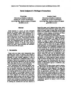
Machine learning is the branch of AI dealing with the assimilation of knowledge, making generalizations, and applying those generalizations to some task. Q-Learning is a type of reinforcement learning. Reinforcement learning is learning where there is feedback in the form of some reward. This feedback reinforces outcomes that are deemed favorable. With Q-Learning, an agent learns an action-value function, which gives the expected utility of taking an action in a given state [4]. Figure 2.2 depicts a grid world in which an agent may learn the utility of moving each direction given an initial position. The squares with −1 are pits, while the square with +1
18
-1
-1
+1
START
Figure 2.2: Q-Learning Grid World is gold. In this world, an agent will learn different values for each action. This will cause it to move away from the pits and toward the gold. While machine learning has been utilized in multiagent systems, it has not been as broadly applied to the organizational aspects of multiagent systems. While machine learning has been used at the agent and individual agent task levels directly, policies are a natural way to apply machine learning to the organizational characteristics of a multiagent systems. Policies are cross-cutting instruments, having a direct and clear effect on the overall performance of an organization.
2.10.2
Satisfiability
Satisfiability, is the general problem where one has a Boolean formula of free variables and the question is asked: “is there a set of assignments to variables that will cause the entire Boolean formula to evaluate to true?” In the general case, this problem is NP-hard [36]. For this reason, there are many algorithms that have been developed using techniques from AI to solve satisfiability problems using various heuristics in an a timely manner. The heuristics take advantage of the structure and common types of satisfiability questions that
19
are normally asked. As we will see later in this thesis, some satisfiability engines employ learning in the process. Policies as a formal specification lend themselves to analysis techniques, which have been used heavily in program analysis. Satisfiability can be used to answer questions about the policies and the models that are used to create multiagent systems.
2.11
Conclusions
Multiagent systems are composed of a group of autonomous agents. In a cooperative environment, they work together to achieve a common goal. Multiagent systems are expected to be robust, reliable, adaptive, and autonomous. Organization-based MAS have been proposed as a way of dealing with coordination, communication, and goals in a general manner. In organization-based MAS, the concepts of goals, roles, protocols, policies, and ontology are introduced. Electronic institutions take this one step further by making concrete the organization in the system as an entity itself. There are several frameworks for organization-based MAS, namely OperA, MOISE+ , and OMACS. A number of software engineering methodologies have been developed to construct organization-based MAS, e.g., Gaia, ADELFE, Prometheus, Tropos, and O-MaSE. Policies and norms have been used to constrain and form systems built using organizationbased MAS software engineering methodologies; KAoS and PONDER being two popular systems. Program analysis and artificial intelligence techniques have matured in the last decade to become a viable tool in the analysis and design of these policies for large systems. Policies have proven to be useful in the development of multiagent systems. However, if implemented inflexibly, situations such as described in [51] will occur (a policy caused a spacecraft to crash into an asteroid). For this reason, we investigate an approach using policies that will not overly constrain the system.
20
Chapter 3 Guidance and Law Policies 3.1
Introduction
As computer systems have been charged with solving problems of greater complexity, the need for distributed, intelligent systems has increased. As a result, there has been a focus on creating systems based on interacting autonomous agents. This investigation has created an interest in multiagent systems and multiagent system engineering, which proscribes formalisms and methods to help software engineers design multiagent systems. One aspect of multiagent systems that is receiving considerable attention is the area of policies. These policies have been used to describe the properties of a multiagent system–whether that be behavior or some other design constraints. Policies are essential in designing societies of agents that are both predictable and reliable [37]. Policies have traditionally been interpreted as properties that must always hold. However, this does not capture the notion of policies in human organizations, as they are often used as normative guidance, not strict laws. Typically, when a policy cannot be followed in a multiagent system, the system cannot achieve its goals, and thus, it cannot continue to perform. In contrast, policies in human organizations are often suspended in order to achieve the overall goals of the organization. We believe that such an approach could be extremely beneficial to multiagent systems residing in a dynamic environment. Thus, we want to enable developers to guide the system without constraining it to the point where it cannot function effectively or looses its autonomy.
21
3.1.1
Contributions
The main contributions of this chapter are: (1) a formal trace-based foundation for law (must always be followed) and guidance (need not always be followed) policies, (2) a conflict resolution strategy for choosing between which guidance policies to violate, and (3) validation of our approach through a set of simulated multiagent systems.
3.1.2
Chapter Outline
The rest of the chapter is organized as follows. In Section 3.2, we present two motivating multiagent system examples. In Section 3.3, we define the notion of system traces for a multiagent system, which are later used to describe policies. Section 3.4 defines law policies as well as guidance policies; we give examples and show how guidance policies are useful for multiagent systems and describe a method for ordering guidance policies according to importance. Section 3.5 presents and analyzes experimental results from applying policies to the two multiagent system examples. Section 3.6 concludes and presents some future work.
3.2
Motivating Examples
In order to give a clearer demonstration of the usefulness of our formalization, we present two well-known examples in multiagent systems engineering.
3.2.1
Conference Management System
A well known example in multiagent systems is the Conference Management System [38, 39]. The Conference Management System models the workings of a scientific conference. For example, authors submit papers, reviewers review the submitted papers, and certain papers are selected for the conference and printed in the proceedings. Figure 3.1 shows the complete goal model for the conference management system, which we are using to illustrate our policies. In this example, a multiagent system represents the goals and tasks 22
23 «and»
2. Assign papers
4. Select papers
5 Inform authors
4.1 Collect reviews «precedes»
«occurs»
declined(p)
«triggers»
«occurs»
4.2 Make decision
«and»
p : Paper
5.1 Inform declined
«and»
accepted(p)
«triggers»
p : Paper
«precedes»
«triggers»
p : Paper
5.1 Collect finals
5.2 Inform accepted
Figure 3.1: Conference Management Goal Model.
set : PaperSet
«precedes»
p : Paper r : Reviewer
«triggers»
assign(p,r)
«occurs»
2.2 Assign reviewers
«triggers»
created(set)
«occurs»
2.1 Partition papers
«precedes»
«precedes»
1.1 Collect papers
1.2 Distribute papers
«and»
«and»
3. Review paper
6. Print proceedings
1. Get papers
«and»
0. Manage conference submissions
5.2 Send to printer
of a generic conference paper management system. Goals of the system are identified and are decomposed into subgoals. The top-level goal, 0. Manage conference submissions, is decomposed into several “and” subgoals, which means that in order to achieve the top goal, the system must achieve all of its subgoals. These subgoals are then associated through precedence and trigger relations. The precedes arrow between goals indicates that the source of the arrow must be achieved before the destination can become active. The triggers arrow indicates that the domainspecific event in the source may trigger the goal in the destination. The occurs arrow from a goal to a domain-specific event indicates that while pursuing that goal, said event may occur. A goal that triggers another goal may trigger multiple instances of that goal. Leaf goals are goals that have no children. The leaf goals in this example consist of Collect papers, Distribute papers, Partition papers, Assign reviewers, Collect reviews, Make decision, Inform accepted, Inform declined, Collect finals, and Send to printer. For each of these leaf goals to be achieved, agents must play specific roles. The roles required to achieve the leaf goals are depicted in Figure 3.2. The role model gives seven roles as well as two outside actors. Each role contains a list of leaf goals that the role can achieve. For example, the Assigner role can achieve the Assign reviewers leaf goal. In GMoDS, roles only achieve leaf goals. The arrows between the roles indicate interaction between particular roles. For example, once the agent playing the Partitioner role has some partitions, it will need to hand off these partitions to the agent playing the Assigner role. OMACS allows an agent to play multiple roles simultaneously, as long as it has the capabilities required by the roles and it is allowed by the policies.
3.2.2
Cooperative Robotic Floor Cleaning Company
Another example to illustrate the usefulness of the concept of guidance policies is the Cooperative Robotic Floor Cleaning Company (CRFCC), which was first presented by Robby et al.[35]. In this example, a team of robotic agents clean the floors of a building. The team
24
Reviewer
Assigner assigns reviewers
review papers
review paper
Review Collector submit review
collect reviews
get reviews
Decision Maker retrieve paper
make assignments
make decision inform accepted inform declined inform authors
Partitioner partition papers
PaperDB retrieve abstracts
collect papers distribute papers collect finals
submit paper submit final Author
retrieve finals
Finals Collector send to printer
print proceedings
Figure 3.2: Conference Management Role Model.
has a map of the building as well as indications of whether a floor is tile or carpet. Each team member has a certain set of capabilities (e.g. vacuum, mop, etc) that may become defective over time. In their analysis, Robby et al. showed how decomposing the capabilities affected a team’s flexibility to overcome loss of capabilities. We have extended this example by giving the information that the vacuum cleaner’s bag needs to be changed after vacuuming three rooms. Thus, we want to minimize the number of bag changes. Definition 3.1: Flexibility. Flexibility is the ability of the system to reorganize to overcome individual agent failures. [35] The goal model for the CRFCC system is fairly simple. As seen in Figure 3.3, the overall goal of the system (Goal 0) is to clean the floors. This goal is decomposed into three conjunctive subgoals: 1. Divide area, 2. Pickup area, and 3. Clean area. The 3. Clean goal is decomposed into two disjunctive goals: 3.1 Clean tile and 3.2 Vacuum area. Depending on the floor type, only one subgoal must be achieved to accomplish the 3. Clean area goal. If 25
0. Clean floors total : Area
1. Divide area total : Area
2. Pickup area newArea(area)
a : Area
3. Clean area
a : Area
newArea(area) 3.1 Clean tile
3.2 Vacuum area
a : Area
a : Area
3.1.1 Sweep area a : Area
3.1.2 Mop area
a : Area
Figure 3.3: CRFCC Goal Model. an area needs to be swept and mopped (i.e. it is tile), then goal 3.1 Clean tile is decomposed into two conjunctive goals: 3.1.1 Sweep area and 3.1.2 Mop area. After an agent achieves the 1. Divide area goal, a certain number of 2. Pickup area and 3. Clean area goals will be triggered (depending on how many pieces the area is divided into). After the 2. Pickup area goals are completed, the 3. Clean area goals will activate goals for the tile areas (3.1.1 Sweep area and 3.1.2 Mop area) as well as goals for the carpeted areas (3.2 Vacuum area). Figure 3.4 gives the role model for the CRFCC. In this role model, each leaf goal of the system is achieved by a specific role. The role model may be designed many different ways depending on the system’s goal, agent, and capability models. Thus, depending on the agents and capabilities available, the system designer may choose different role models. For this thesis, we consider only one of these possible role models. In the role model in Figure 3.4, the only role requiring more than one capability is the Pickuper role. This role requires both the search and move capability. Thus, in order to play this role, an agent must possess both capabilities. 26
Organizer
Pickuper
org 1. Divide area
pickup
search move 2. Pickup area
mop
sweep
Sweeper
Mopper
sweep 3.1.1 Sweep area
mop 3.1.2 Mop area
vacuum
Vacuummer
vacuum 3.2 Vacuum area
Figure 3.4: CRFCC Role Model.
27
3.3
Multiagent Traces
There are several observable events in an OMACS system. A system event is simply an action taken by the system. We are concerned with specific actions that the organization takes. For instance, an assignment of an agent to a role is a system event. The completion of a goal is also a system event. In an OMACS system, we can have the system events of interest shown in Figure 3.5a. At any stage in system execution, there may be certain properties of interest. Some are domain-specific (only relevant to the current system), while others are general properties such as the number of roles an agent is currently playing. State properties that are relevant to the conference management CRFCC systems are shown in Figure 3.5b. Event C(gi ) T (gi ) A(ai , rj , gk )
Definition goal gi has been completed. goal gi has been triggered. agent ai has been assigned role rj to achieve goal gk . (a) System Events.
Property a.reviews a.vacuumedRooms
Definition the number agent a has the number agent a has
of reviews performed. of rooms vacuumed.
(b) Properties
Figure 3.5: Events and Properties of Interest.
3.3.1
System Traces
In order to describe multiagent system execution, we use the notion of a system trace. An (abstract) system trace is a projection of system execution with only desired state and event information preserved (role assignments, goal completions, domain-specific state property changes, etc).
28
We are only concerned with the events and properties given above and only traces that result in a successful completion of the system goal. Let E be an event of interest and P be a property of interest. A change of interest in a property is a change for which a system designer has made some policy. For example, if a certain integer should never exceed 5, a change of interest would be when that integer became greater than 5 and when that integer became less than 5. Thus a change of interest in a property is simply an abstraction of all the changes in the property. Definition 3.2: Change of interest. A change of interest in property P is an event where the value associated with P has been updated and P is used in a policy. ∆P indicates a change of interest in property P . A system trace may contain both events and changes of interest in properties. Changes of interest in properties may be viewed as events, thus, for simplicity we include both and use both interchangeably. Thus, a system trace is defined as: Definition 3.3: System trace. A system trace is a projection of a sequence of system events with only desired state and event information preserved. E1 → E2 → . . .
(3.1)
As shown in Formula 3.1, a trace is simply a sequence of events. An example subtrace of a multiagent system, where g1 is a goal, a1 is an agent, and r1 is a role, might be: . . . T (g1 ) → A(a1 , r1 , g1 ) → C(g1 ) . . .
(3.2)
Formula 3.2 means that goal g1 is triggered, then agent a1 is assigned role r1 to achieve goal g1 , finally, goal g1 is completed. We use the terms legal trace and illegal trace. An illegal trace is an execution path that we do not want our system to exhibit, while a legal trace is an execution path that our system may exhibit. Intuitively, policies cause some traces to become illegal, while others remain legal. 29
Definition 3.4: Subtrace. A subtrace is a subsequence of the events within a trace. E.g., if we have the trace E1 → E2 → E3 , then one possible subtrace is E2 → E3 . Definition 3.5: Legal trace. A legal trace is a sequence of events for which no subsequence (subtrace) violates a given set of constraints. Definition 3.6: Illegal trace. An illegal trace is a sequence of events in which a subsequence (subtrace) exists that violates a given set of constraints. We are able to use the notion of system traces because the framework we are using to build multiagent systems constructs mathematically specified models[1, 8] of various aspects of the system (goal model, role model, etc.). This can be leveraged to formally specify policies as restrictions of system traces. Now that we have a formal definition of system traces, we can leverage existing research on property specification and concurrent program analysis.
3.4
Policies
Policies may restrict or proscribe behaviors of a system. Policies concerning agent assignments to roles have the effect of constraining the set of possible assignments. This can greatly reduce the search space when looking for the optimal assignment set [40]. Other policies can be used for verifying that a goal model meets certain criteria. This allows the system designer to more easily state properties of the goal model that may be verified against candidate goal models at design time. For example, one might want to ensure that our goal model in Figure 3.1 will always trigger a Review Paper goal for each paper submitted. Yet, other policies may restrict the way that roles can be played. For example, when an agent is moving down the sidewalk it always keeps to the right. These behavior policies also restrict how an agent interacts with its environment, which in turn means that they can restrict protocols and agent interactions. One such policy might be that an agent playing 30
the Reviewer role must always give each review a unique number. These sort of policies rely heavily on domain-specific information. Thus it is important to have an ontology for relevant state and event information prior to designing policies [41].
3.4.1
Language for policy analysis
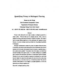
To describe our policies, we use temporal formula with quantification similar to [42], which may be converted into Linear Temporal Logic (LTL) [43] or B¨ uchi automata [44] for infinite system traces, or to Quantified Regular Expressions [45] for finite system traces. The formulas consist of predicates over goals, roles, events, and assignments (recall that an assignment is the joining of an agent and role for the purpose of achieving a goal 2.6.1). The temporal operators we use are as follows: 2(x), meaning x holds always; 3(x), meaning x holds eventually; and x U y, meaning x holds until y holds.1 We use a mixture of state properties as well as events [46] to obtain compact and readable policies. An example of one such policy formula is: ∀a1 : Agents, L :2(sizeOf (a1 .reviews) ≤ 5)
(3.3)
Formula 3.3 states that it should always be the case that each agent never review more than five papers. The L : indicates that this is a law policy. The property .reviews can be considered as part of the system’s state information. This is domain-specific and allows a more compact representation of the property. This policy may be easily represented by a finite automata as shown in Figure 3.6. Definition 3.7: Law policy. A Law Policy is a rule or formula that must hold true for every subtrace of our system traces. The use of the A() predicate in Figure 3.6 indicates an assignment of the Reviewer role to achieve the Review paper goal, which is parametrized on the paper p. This automata depicts the policy in Formula 3.3, but in a manner that allows a model checker or some 1
We only reason about bounded liveness properties because we only consider successful traces.
31
a.reviews = 5 ^ A(a, REVIEWER, Review(p))
a.reviews > 5
Bad
a.reviews ≤ 5
∀a: Agents, p : Papers a.reviews < 5 ⋁ ¬A(a, REVIEWER, Review(p))
*
Figure 3.6: No agent may review more than five papers. other policy enforcement mechanism to detect when violation occurs. The accepting state indicates that a violation has occurred. Normally, this automata would be run alongside the system, either at design time with a model checker [33], or at run-time with some policy enforcement mechanism [47]. We would like to emphasize here that we do not necessarily expect the designer to specify their policies by hand editing LTL. LTL is complex and designing policies in LTL would be error prone and thus could potentially mislead the designer into a false sense of security or simply to compose incorrect policies. There has been some work in facilitating the creation of properties in LTL (and other formalisms) for program analysis such as specification patterns [48]. There has also been work done to help system property specification writers to graphically create properties [49] (backed by LTL) by manipulating automata and answering simple questions regarding elements of the property.
3.4.2
Law Policies
The traditional notion of a policy is a rule that must always be followed. We refer to these policies as law policies. An example of a law policy with respect to our conference management example would be no agent may review more than five papers. This means that our system can never assign an agent to the Reviewer role more than five times. A law 32
policy can be defined as: L :Conditions → P roperty
(3.4)
Conditions are predicates over state properties and events, which, when held true, imply that the P roperty holds true. The Conditions portion of the policy may be omitted if the P roperty portion should hold in all conditions, as in Formula 3.3. Intuitively, for the example above, no trace in the system may contain a subtrace in which an agent is assigned to the Reviewer role more than five times. This will limit the number of legal traces in the system. In general, law policies reduce the number of legal traces for a multiagent system. The policy to limit the number of reviews an agent can perform is helpful in that it will ensure that our system does not overburden any agent with too many papers to review. This policy as a pure law policy, however, could lead to trouble in that the system may no longer be able to achieve its goal. Imagine that more papers than expected are submitted. If there are not sufficient agents to spread the load, the system will fail since it is cannot assign more than five papers to any agent. This is a common problem with using only law policies. They limit the flexibility of the system, which we define as how well the system can adapt to changes [35].
3.4.3
Guidance Policies
While the policy in (3.3) is a seemingly useful policy, it reduces flexibility. To overcome this problem, we have defined another, weaker type of policy called guidance policies. Take for example the policy used above, but as a guidance policy: ∀a1 : Agents, G :2(sizeOf (a1 .reviews) ≤ 5)
(3.5)
This is the same as the policy as in (3.3) except for the G :, which indicates that it is a guidance policy. In essence, the formalization for guidance and law policies are the same, the difference is the intention of the system designer. Law policies should be used when the designer wants to make sure that some property is always true (e.g. for safety or security), while guidance policies should be used when the designer simply wants to guide the system. 33
Node P1 P2 P3 P4
Definition No agent should review more than 5 papers. PC Chair should not review papers. Each paper should receive at least 3 reviews. An agent should not review a paper from someone whom they wrote a paper with.
Table 3.1: Conference Management Policies. This guidance policy limits our agents to reviewing no more than five papers, when possible. Now, the system can still be successful when it gets more submissions than expected since it can assign more than five papers to an agent. When there are sufficient agents, the policy still limits each agent to five or fewer reviews. Definition 3.8: Guidance policy. A Guidance Policy is a rule or formula that must hold true for every subtrace of our system trace, when there is a potential system trace for which this is possible. Guidance policies more closely emulate how policies are implemented in human societies. They also provide a clearer and simpler construct for more easily and accurately describing the design of a multiagent organization. In contrast to policy resolution complexity of detecting and resolving policy contradictions in other methods [24], our methodology of using guidance policies presents an incremental approach to policy resolution. That is, the system will still work under conflicting policies and its behaviors are amenable to analysis, thus allowing iterative policy refinement. In the definition of guidance policies, we have not specified how the system should choose which guidance policy to violate in a given situation. There are many ways these policies could be violated. We could allow arbitrary or random violation. In many cases, however, the designer has a good idea of how important each policy is relative to each other. For this we could have used some absolute scale, giving each policy an importance score. This would force a total ordering of policies, which may not always be the intent of the designer. There may be cases where one policy is no more important than another. For this reason, we 34
propose a partial ordering of guidance policies to allow the system designer to set precedence relationships between guidance policies. We arrange the guidance policies as a lattice, such that a policy that is a parent of another policy in the lattice, is more-important-than its children. By analyzing a system trace, one can determine a set of policies that were violated during that trace. This set of violations may be computed by examining the policies and checking for matches against the trace. When there are two traces that violate policies with a common ancestor, and one (and only one) of the traces violate the common ancestor policy, we mark the trace violating that common ancestor policy as illegal. Intuitively, this trace is illegal because the system could have violated a less important policy. Thus, if the highest policy node violated in each of the two traces is an ancestor of every node violated in both traces, and that node is not violated in both traces, then we know the trace violating that node is illegal and should not have happened. Take, for example, the four policies in the Table 3.1. Let these policies be arranged in the lattice shown in Figure 3.7a. The lattice in Figure 3.7a means that policy P1 is more important than P2 and P3 , and P2 is more important than P4 . Thus, if there is any trace that violates any guidance policies other than P1 (and does not violate a law policy), it should be chosen over one which violates P1 . When a system cannot achieve its goals without violating policies, it may violate guidance policies. There may be traces that are still illegal, though, depending on the ordering between policies. Definition 3.9: Illegal trace wrt. guidance policies. An illegal trace with respect to guidance policies is a trace with a set of policy violations P, such that for every pair of traces, if the least upper bound of the policies violated in both traces, P, is in one (and only one) of the traces. For example, consider the ordering in Figure 3.7a, let trace t1 violate P1 and P2 , while trace t2 violates P2 and P3 . Round nodes represent policies violated in t1 , box nodes represent 35
P1
P2
P1
P3
P2
P4
P3
P4
(a) Possible Partial order of Guidance Policies.
(b) Another possible ordering.
Figure 3.7: Partial orders of Guidance Policies. policies violated in t2 , and boxes with rounded corners represent policies violated in both t1 and t2 . Since P1 is the least upper bound of P1 , P2 , and P3 and since P1 is not in t2 , t1 is illegal. As shown in Figure 3.7b, the policies may be ordered in such a way that the policy violations of two traces do not have a least upper bound. If there is no least upper bound, P, such that P is in one of the traces, the two traces cannot be compared and thus both traces are legal. The reason they cannot be compared is that we have no information about which policies are more important. Thus, either option is legal. It is important to see here that all the guidance policies do not need to be ordered into a single lattice. The system designer could create several unrelated lattices. These lattices then can be iteratively refined by observing the system behaviors or by looking at metrics generated for a certain policy set and ordering[35]. This allows the system designer to influence the behavior of the system by making logical choices as to what paths are considered better. Using the lattice in 36
Figure 3.7a, we may even have the situation where P1 is not violated by either trace. In this case, the violation sets cannot be compared, and thus, both traces are legal. In situations such as these, the system designer may want to impose more ordering on the policies. Intuitively, guidance policies constrain the system such that at any given state, transitions that will not violate a guidance policy are always chosen over transitions that violate a guidance policy. If guidance policy violation cannot be avoided, a partial ordering of guidance policies is used to choose which policies to violate.
3.5 3.5.1
Evaluation CRFCC
Using our CRFCC example and a modified simulator [35], we collected results running simulations with the guidance policy: no agent should vacuum more than three rooms. We contrast this with the law policy: no agent may vacuum more than three rooms. The guidance policy is presented formally in Equation 3.6. ∀a1 : Agents, G :2(a1 .vacuumedRooms ≤ 3)
(3.6)
For this experiment, we used five agents each having the capabilities as shown in Figure 3.8. These capabilities restrict the roles our simulator can assign to particular agents. For example, the Organizer role may only be played by agent a1 or agent a5 , since those are the only agents with the org capability. In the simulation we randomly choose capabilities to fail based on a probability given by the capability failure rate. Agent a1 a2 a3 a4 a5
Capabilities org, search, move search, move, vacuum vacuum, sweep sweep, mop org, mop
Figure 3.8: CRFCC Agent model
37
For each experiment, the result of 1000 runs at each capability failure rate was averaged. At each simulation step, a goal being played by an agent is randomly achieved. Using the capability failure rate, at each step, a random capability from a random agent may be selected to fail. Once a capability fails it cannot be repaired. Figure 3.9 shows that while the system success rate decreases when we enforce the law policy, it does not, however, decrease when we enforce the guidance policy. Figure 3.10 shows the total number of times the system assigned vacuuming to an agent who already vacuumed at least 3 rooms for 1000 runs of the simulation at each failure rate. With no policy, it can be seen that the system will in fact assign an agent to vacuum more than 3 rooms quite often. With the guidance policy, however, the extra vacuum assignments (> 3) stay minimal. The violations of the guidance policy increase as the system must adapt to an increasing failure of capabilities until it reaches a peak. At the peak, increased violations do not aid in goal achievement and eventually the system cannot succeed even without the policy. Thus, the system designer may now wish to purchase equipment with a lower rate of failure, or add more redundancy to the system to compensate. The system designer may also evaluate the graph and determine whether the cost of the maximum number of violations exceeds the maximum cost he is willing to incur, and if not, make appropriate adjustments.
3.5.2
Conference Management System
We also simulated the conference management system described in Section 3.2.1. We held the number of agents constant, while increasing the number of papers submitted to the conference. The system was constructed with a total of 13 agents, 1 PC Member agent, 1 Database agent, 1 PC Chair agent, and 10 Reviewer agents. The simulation randomly makes goals available to achieve, while still following the constraints imposed by GMoDS. Roles that achieve the goal are chosen at random as well as agents that can play the given role. The policies are given priority using the more-important-than relation as depicted in Figure 3.7a.
38
39
System Success Percentage
0
20
40
60
80
100
0
10
30
40 50 60 Capability Failure Percentage
70
80
Figure 3.9: The success rate of the system given capability failure.
20
90
Guidance Policy No Policy Law Policy
100
40
Total Extra Vacuum Assignments (>3)
0
200
400
600
800
1000
1200
1400
1600
0
20
30
40 50 60 Capability Failure Percentage
70
80
Figure 3.10: The extra vacuum assignments given capability failure.
10
90
Guidance Policy No Policy
100
41
Policy Violations
0
20
40
60
80
100
120
140
160
180
200
10
20
30
40 50 60 Papers Submitted for Review
70
80
90
Figure 3.11: Violations of the guidance policies as the number of papers to review increases.
0
P1 - No more than 5 papers should be reviewed by an agent P2 - PC Chair should not review papers P3 - Every paper receives at least 3 reviews (total reviews missing)
100
Figure 3.11 shows a plot of how many times a guidance policy is violated versus the number of papers submitted for review. For each set of paper submissions (from 1 to 100) we ran the simulation 1000 times and then took the average of the 1000 runs to determine the average number of violations. In all the runs the system succeeded in achieving the top level goal. As seen by the graph in Figure 3.11, no policies are violated until around 17 papers (this number is explained below). The two least important policies (P2 and P3 ) are violated right away. The violation of P2 , however, levels off since it is interacting with P1 . The violations of P3 are seen to grow at a much greater rate since P3 is the least important policy. We then changed all the guidance policies to law policies and re-ran the simulation. For 17 or more submissions, the system always failed to achieve the top level goal. This makes sense because we have only 10 Reviewer agents and we have the policies: the PC Chair should not review papers and no agent should review more than 5 papers. This means the system can only produce 5 × 10 = 50 reviews. But, since we have the policy that each paper should have at least 3 reviews, 17 submissions would need 17 × 3 = 51 reviews. For 16 or fewer papers submitted, the law policies perform identical to the guidance policies.
3.5.3
Common Results
As the experimental results in Figure 3.9 show, guidance policies do not decrease the flexibility of a system to adapt to a changing environment, while law policies do decrease the flexibility of a system to adapt to a changing environment. Guidance policies, however, do help guide the system and improve performance as shown in Figure 3.10 and Figure 3.11. The partial ordering using the more-important-than relation helps a system designer put priorities on what policies they consider to be more important and helps the system decide which policies to violate in a manner consistent with the designer’s intentions.
42
3.6
Conclusions
Policies have proven to be useful in the development of multiagent systems. However, if implemented inflexibly, situations such as described in [51] will occur (a policy caused a spacecraft to crash into an asteroid). Guidance policies allow a system designer to guide the system while giving it a chance to adapt to new situations. With the introduction of guidance policies, policies are an even better mechanism for describing desired properties and behaviors of a system. It is our belief that guidance policies more closely capture how policies work in human organizations. Guidance policies allow for more flexibility than law policies in that they may be violated under certain circumstances. In this chapter, we demonstrated a technique to resolve conflicts when faced with the choice of which guidance policies to violate. Guidance policies, since they may be violated, can have a partial ordering. That is, one policy may be considered more important than another. In this manner, we allow the system to make better choices on which policies to violate. Traditional policies may be viewed as law policies, since they must never be violated. Law policies are still useful when the system designer never wants a policy to be violated–regardless of system success. Such policies might concern security or human safety. Policies may be applied in an OMACS system by constraining assignments of agents to roles, the structure of the goal model for the organization, or how the agent may play a particular role. Through the use of OMACS, the metrics described in [35], and the policy formalisms presented here, we are able to provide an environment in which a system designer may formally evaluate a candidate design, as well as evaluate the impact of changes to that design without deploying or even completely developing the system. Policies can dramatically improve run-time of reorganization algorithms in OMACS as shown in [40]. Guidance policies can be a way to achieve this run-time improvement without sacrificing system flexibility. The greater the flexibility, the better the chance that the system will be able to achieve its goals. Policies are difficult to write and even more difficult to conceive. For this reason, we 43
need to automate the process and to better aid the designer in creating guidance policies. One way to help automate this process is through the use of machine learning. In the next chapter, we show one method of using learning to automatically create guidance policies at runtime.
44
Chapter 4 Learning Policies to Self-Tune Systems 4.1
Introduction
As we saw in Chapter 3, guidance policies are a useful abstraction for helping us tame the autonomous nature of multiagent systems, without sacrificing the flexibility to overcome changes in the environment. However, these policies are difficult to write and difficult to optimize for the variety of environments in which we will deploy the system. For this reason, we explore learning some of these policies during the runtime of the system. In multiagent software engineering, agents interact and can be given tasks depending on their individual capabilities. The system designer, however, may not have planned for every possible environment within which the system may be deployed. The agents themselves may exhibit particular properties that were not initially anticipated. As multiagent systems grow, configuration and tuning of these systems can become as complex as the problems they claim to solve. A robust system should adapt to environments, recover from failure, and improve over time. In human organizations, policies evolve over time and are adapted to overcome failures. New policies are introduced to avoid unfavorable situations. A robust organization-based multiagent system should also be able to evolve its policies and introduce new ones to avoid
45
undesirable situations. Learning from mistakes is one of the most common learning methods in human society. Learning from mistakes allows one to improve performance over time, this is commonly referred to as experience. Experience can allow proper tuning and configuration of a complex multiagent system. In this chapter, we implement this tuning and configuration through the mechanism of organizational guidance policies. Applying learning in multiagent systems is not new. Many authors have explored applying various learning techniques in a multiagent context [52–54]. Most of these learning applications, however, have been limited to improving an agent’s performance at some task, but not the overall organization’s performance. Some consider the overall team performance, but not in the structure of modern organization-based multiagent systems. Reasoning over an entire multiagent system is a momentous task [55]. Care must be taken to ensure that learned policies do not negatively impact the organization, for example, putting the organization in a situation where it is impossible for it to complete its goal. Interactions between policies can be subtle and many hidden interactions may exist. Our use of guidance policies helps mitigate these risks substantially, thus allowing the system to experiment with different policies without the risk to the viability of the system.
4.1.1
Contributions
The main contributions of this chapter are: (1) an organizational policy-based approach to self-tuning, (2) a generalized algorithm based on Q-Learning to implement the policy-based tuning, and (3) empirical validation of our approach through a set of simulated multiagent systems.
4.1.2
Chapter Outline
The rest of the chapter is organized as follows. In Section 4.2, we present our policy learning algorithm. Section 4.3 presents and analyzes experimental results from applying our policy learning algorithm to three multiagent system examples. Section 4.4 presents some 46
limitations of our approach. Related work is presented in Section 4.5. Section 4.6 gives conclusions.
4.2
Self-Tuning Mechanism
An overview of how the learning takes place in our systems is given in Figure 4.1. The system first checks the goals that are available to be worked on; these goals come from GMoDS using the precedence and trigger mechanisms and support the overall goal of the system. Assignments of goals and the roles that can achieve them are given to the agents. The agents then indicate achievement failure or success. If an agent fails to achieve a goal, policies are learned over the current state knowledge. This cycles until either the system cannot achieve the main goal (system failure), or the system achieves the main goal (system success). Agents may fail to achieve a goal due to some aspect of the goal or due to some changes in the environment. The failure may be intermittent and random. Definition 4.1: System State. A system state is a projection of a system’s history (event sequence). That is, it is a compressed (perhaps lossy) record of events in a system.
Definition 4.2: Goal achievement failure. A goal achievement failure is an event in which an agent decides that it can no longer complete a particular goal. The aim of our learning algorithm is to discover new guidance policies in order to avoid ‘bad states’. Thus we generate only negative authorization policies. While the precise definition of a bad state is domain specific, we assume that the set of bad states is a possibly empty subset of all the states in the system. The remaining states are good states. Thus we have S = SB ∪ SG and SB ∩ SG = ∅, where S is the set of all states in the system, SG is the set of all good states in the system, and SB is the set of all bad states in the system. Generally, bad states are states of the system that should be avoided. We use a scoring mechanism to determine which states are considered bad. The score of a state is domain
47
Agent-Goal Achievement Success
Check Active Goals
Assign Goal-Role to Agents
Agent-Goal Achievement Failure
Learn Policies
Figure 4.1: Learning Integration. specific, however, for our experiments we used score(Si ) =
1 , 1+Fi
where Fi is the number of
agent goal achievement failures thus far in state Si . Definition 4.3: Negative authorization policy. A negative authorization policy is a rule that disallows a particular action in certain cases. To actually generalize and not simply memorize, our learning algorithm should derive policies that apply to more than one state through generalization. In this way, the learner attempts to discover the actual cause for the bad state so that it may avoid the cause and not simply avoid a single bad state. For example, the system may detect that when the system does X, then Y , and then Z it reaches a bad state. However, this bad state may simply be a result of performing action Y and Z. Thus, we want the system to realize that it should try to avoid performing action Y and then action Z. The exact mechanism we are using will become more clear in the proceeding sections. Our learning algorithm takes a Q-Learning [56] approach. The learner keeps track of 48
Si {...}
Si+1 T = < Gi( x ), Rj , Ak >
Fi = n
{...} U T
Fi+1 = Fi + 1
Figure 4.2: State and Action Transition. both bad and good actions (transitions) given a state. Definition 4.4: Bad actions. Bad actions given a state are defined as actions that result in a state that has a score lower than the state in which the action took place. Definition 4.5: Good actions. Good actions given a state are defined as actions that result in a state that has a score equal to or greater than the score of the state in which the action took place. The learner can then generate a set of policies that will avoid the bad states (by avoiding the bad action leading to this state). In the context of the experiments presented in this chapter, the actions considered are agent goal assignments. Definition 4.6: Agent goal assignment. An agent goal assignment is defined as a tuple, hGi (x), Rj , Ak i, containing a parametrized goal Gi (x), a role Rj , and an agent Ak . The goal’s parameter x may be any domain specific specialization of the goal Gi given at the time the goal is dispatched (triggered) to the system. Figure 4.2 shows an example state transition. In this example, state Si is transitioning to state Si+1 via assignment T . In state Si+1 a failure occurs, thus Fi+1 = Fi + 1. The state is then given a score. Generalization of the policies is done over the state. For each action leading to a bad state, the algorithm first checks to see if we already have a policy covering this action 49
with the pre-state (state leading to the bad state), if so, nothing needs to be done for this bad action, otherwise we generate a policy for it. The algorithm generalizes the state by considering matchings. Definition 4.7: Matching. A matching is a binary relation between a substate and a state. Bk ≺ Si , means that Bk matches Si . Intuitively, a matching occurs between a state and substate when the substate represents some part of the state. Figure 4.3 depicts the substate matching relationship. Each letter represents a state quantum. Definition 4.8: State quantum. A state quantum is the smallest divisible unit within a state. Definition 4.9: Unordered State. An unordered state is a system state in which there is no ordering to the state quantum. For example, the set of current capabilities of the system can be viewed as a system state, which does not have a defined ordering. Definition 4.10: Ordered State. An ordered state is a system state in which there is a defined ordering to the state quantum. For example, a history of events can be viewed as a system state in which the quanta (events), have a defined ordering. In the unordered state, a matching substate may consist of any subset of state quanta. In the ordered state, the order of the quanta must be preserved in the substate. The empty substate is said to match all states. If a state is a set of unordered quanta, Si = {s1 , s2 , ...}, then a substate, Bk , is said to be a matching for Si iff Bk ⊆ Si . In practice, since the number of ordered states for a given system is far greater than the number of unordered states for the same system, we tend to prefer using unordered states over ordered states. Using ordered states would give the learner more information, but in the experiments we have conducted, that extra information was not worth the added state space. State space explosion with the ordered states was not offset by performance gains over the unordered 50
Ordered State
Unordered State
Matching Substate CD
Matching Substate ABCDE
AD
AC D B
Figure 4.3: Ordered and Unordered states and their matching substates. version. In our experiments, we used agent role-goal assignment and achievement history as our states. The quanta are the actual agent assignment tuples. A substate is said to match a state when the agent assignment tuples in the achievement and assignment sets of the substate are subsets of the corresponding sets of the state. Intuitively, substates may be seen as generalizations of states. The operation of the algorithm is independent of the state score calculation and the substate generation. For every bad action, T , given a state, the algorithm starting with the empty substate, which matches all states, computes a score using Formula (4.1). If this score is lower than a threshold, the algorithm asks the state for the set of smallest substates containing a specific substate (initially the empty substate). Each one of these substate-action pairs, (Bk , T ), are given a score, score(Bk , T ) = 1 −
size(matchG ) size(statesG ) + size(statesB ) + size(matchB )
(4.1)
The variables in Formula (4.1) are as follows: statesG is the entire set of good states given the transition T (gotten to by taking transition T ); statesB is the entire set of bad states given the transition T (gotten to by taking transition T ); matchG is, given the transition, the set of good states that the substate matches (a subset of statesG ); and matchB is, given the transition T , the set of bad states that the substate matches (a subset of statesB . It follows that the score is bounded as follows: 0 ≤ score(Bk , T ) ≤ 1 51
(4.2)
It can easily be seen that when the substate matches all good states, and we have not encountered any bad states size(statesG ) = size(matchG ) and size(statesB ) = size(matchB ) = 0, thus score(Bk , T ) = 0.
Conversely, if the substate does not match any good states,
size(matchG ) = 0, thus score(Bk , T ) = 1. Each substate is scored with Formula (4.1). The substate with the highest score is chosen. If this score is less than a threshold constant, the process is repeated but the substate that is given to the state to generate new substates is this maximum score substate. Thus we now build upon this substate and make it more specific. Intuitively we start with the most general policy and then make it as specific as necessary (taking a greedy approach) so that we exclude ‘enough’ good states. The closer the threshold constant is to 1, the lower the possibility of the learned policies applying to good states. The closer the threshold constant is to 0, the higher the possibility that the learned policies will apply to some good states. For our experiments, we used a threshold constant of 0.6. This proved to perform sufficiently well for us since we dealt with intermittent failures. Pseudo-code for the policy generation is given in Figure 4.4. The nature of our scoring mechanism best fits a greedy approach since we want to achieve the highest scoring trace. A random approach would not fit well here, since it would not be guided by the score. However, would could use a random approach when we are enforcing these policies. This research is outside the scope of this thesis. While lookahead could potentially improve this approach, lookahead causes an exponential increase in execution time. Because this learning algorithm is employed during runtime, an exponential increase in runtime is not practical. Our learning employs a decay on the learned information. This is implemented by heavily favoring new information over historic information. That is, when an update is made to the score, we average the previously computed score with the new score. The new information is always makes up 50% of the new score. This allows us to adapt quickly to changes in the environment and yet not swing too wildly in the case of outlying information.
52
for all haction, preStateSeti in badT GivenS do for all preState in preStateSet do if !isAlreadyMatched(action, preState) then maxSubstate = emptySubstate maxScore =score(maxSubstate, action) done =false while maxscore < T HRHLD∧ !done do substateSet =getSubstates(preState, maxSubstate) if substateSet = ∅ then done = true end if maxScore = -1 for all substate in substateSet do score = score(substate,action) if score > maxScore then maxScore = score maxSubstate = substate end if end for end while matches = matches ∪ haction, maxSubstatei policies = policies∪ generatePolicy(action, maxSubstate) end if end for end for Figure 4.4: Pseudo-code for generating the policies from the state, action pair sets.
53
Another approach that we tested was to avoid the bad states, that is, we ignored transitions and simply constructed policies that avoided generalizations (substates) of the bad states themselves. This alone can lead to problems. In our experiments, we found cases in which the system would live-lock. Since the learner never kept track of the event that lead to the bad state, it was possible that the learner might discover policies that forbid every agent but one from trying to achieve some goal. However, if this one agent failed with 100% probability, the system might simply reinforce that the new bad state was caused by the older decisions (substate) and would keep trying to assign the goal to the failing agent. The action-substate learner gets around this because the policies are developed for the action, if an action keeps leading to a bad state, there will be a policy discovered that forbids it. In the case where there are policies forbidding every agent from trying to achieve a goal, since we are using guidance policies, the policies will be suspended and an agent will be chosen. Eventually an agent who can achieve the goal will be chosen, and the learner will learn that that agent was not the cause of the previous failures. To avoid live-lock, we regenerate policies after every failure.
4.3
Evaluation
To test our algorithm, we simulated three different systems: a conference management system, an information system, and an improvised explosive device (IED) detection cooperative robotic system. These systems are a sampling across the usual multiagent system deployments: the conference management system is a human agent system, the information system is a software agent system, and the IED detection system is a robotic agent system. Each of these systems exhibit special tuning requirements given their different agent characteristics. We simulated these systems by randomly choosing an active goal to achieve and then randomly choosing an agent capable of playing a role that can achieve the goal while following all current policies in the system. Active goals are simply goals that are available to be worked on. With GMoDS, a goal may become active when triggered, or when precedence is
54
resolved. In the case of learning, the learning code receives all events of the system. After every agent goal achievement failure, the system regenerates its learned guidance policies using all of the state, transition, and score information it has accumulated up to that point.
4.3.1
Conference Management System
Recall the Conference Management System as described in Section 3.2.1. We have modified the agents such that some of them fail to achieve their goal under certain conditions. In this system we have three types of Reviewer agents: one that never fails when given an assignment, another that fails 70% of the time after completing two reviews (Limit Reviewer), and the last type, that fails 70% of the time when trying to review certain types of papers (Specialized Reviewer). We also have the constraints that a paper must receive 3 reviews and that no reviewer should review more than 5 papers. We used the GMoDS goal model and role model for the Conference Management system as described in Section 3.2.1. In the Conference Management system, we focused on failures of agents to achieve the Review Paper goal. We created the Reviewer types described above and observed the system performance. In this simulation, we varied the number of papers submitted for review to trigger the failure states. For our experiment, states contain the history of assignments and number of failures thus far. Actions are the assignment and failure events. Only leaf goals are used in assignments. Non-leaf goals are decomposed into the leaf goals. In this experiment, we are concerned with the Reviewer role. Several different agent types are capable of playing this role, although they clearly behave differently. We ran the system with no learning and recorded the number of failures. We then ran the system with the learning engaged and recorded the number of failures. Finally we ran the system with hand-coded policies that we thought should be optimal and recorded the number of failures. The policies generated by the learner consist of forbidding an action given a state match-
55
{, ...}
Figure 4.5: Limit Reviewer policy preventing theory papers from being assigned. ing. For example, the learner discovered the policy: given the empty substate (meaning in any state), forbid the agent assignment hReview papers (Theory), PC Reviewer, Specialized Revieweri. Thus this policy applies to all states of the system and tries to avoid assigning theory papers to the Specialized Reviewer. Another policy discovered by the learner is given the substate Assigned:hReview papers (Theory), PC Reviewer, Limit Revieweri, forbid the action hReview papers (Theory), PC Reviewer, Limit Revieweri. The learner must learn all permutations on the abstracted goal parameter. It is interesting here to note that the learner tries to forbid the Limit Reviewer after just one unsuccessful assignment to it. This has the added benefit that the assignment fails as late as possible, thus the system or environment could have improved before a failure occurs. The number of policies generated is relatively small, staying less than 10 in all runs. Figure 4.5 gives a graphical depiction of how a learned policy relates and is applied to the system states. From a state containing the substate, Assigned:hReview papers ( Theory ), PC Reviewer, Limit Revieweri, the assignment action hReview papers (Theory), PC Reviewer, Limit Revieweri is forbidden. The agent type, role type, goal type, and a parameter abstraction is given. The parameter abstraction is currently domain specific, although a separate learner may categorize the parameters thus creating the abstraction function without the need for a domain expert.
56
57
0
500
1000
1500
2000
2500
3000
3500
4000
4500
5000
0
2
4
6
8 10 12 Papers Submitted for Review
Limit Reviewer (learning) Specialized Reviewer (learning) Limit Reviewer (optimal) Specialized Reviewer (optimal) Limit Reviewer Specialized Reviewer
14
16
18
20
Figure 4.6: Agent goal achievement failures with self-tuning (learning), hand-tuning (optimal), and no tuning.
Failures
Figure 4.6 compares the self-tuning, learning, system to one where this learning does not occur. We also compared the learning to a system, for which, a policy expert with knowledge of the agent goal achievement failure, hand coded policies he thought would tune the system. As can be seen, our learning algorithm does no worse than the hand-coded policies, and does vastly better than a non-tuned system. The learned tuning adapts the system quickly to its deployed environment—without requiring a policy expert to analyze the specific deployment environment and hand-craft policies to tune for said environment. The sharp rise in agent achievement failures is due to the limited number of reviewer agents (10) combined with the constraints we have placed on our system (each paper must have at least 3 reviews and no agent should review more than 5 papers). There is nothing learned nor hand-coded policies can do to prevent failure due to lack of resources.
4.3.2
Information System
Another multiagent system we tested was an Information System. Peer-to-peer information gathering and retrieval systems have been constructed using multiagent systems, e.g. Remote Assistant for Information Sharing (RAIS) [57]. In our information system we had four types of information retrieval agents: CacheyAgent, this agent fails with a 30% probability the first time it is asked for a certain piece of information, subsequent requests for info it has retrieved previously always succeeds; LocalAgent, this agent fails 100% of the time when asked for remote information, otherwise it succeeds with a 100% probability; PickyLocalAgent, this agent fails 100% of the time on any request except for on particular piece of local data; and RemoteAgent, this agent fails 100% of the time on all data except for remote data. The goal model for the Information System is shown in Figure 4.7. The leaf-goals are as follows: 1.1 Monitor Information Search Requests, 1.2.1 Perform Local Search, 1.2.2 Perform Remote Search, 1.2.3 Present Results, 2.1 Monitor Information Requests, 2.2 Retrieve Information, 3.1 Monitor for New Information, and 3.2 Incorporate new Information into Index. This system is basically an information sharing and indexing system. Agents run
58
on client computers monitoring for information changes/additions as well as queries from a user. Information is indexed so that agents can quickly provide results to search queries. Search may be performed locally, or if necessary, a local agent will contact agents residing on other machines for the information. The role-goal relation is shown in Figure 4.8. CacheyAgent is capable of playing roles Local Information Retriever and Remote Information Retriever. LocalAgent and PickyLocalAgent are capable of playing Local Searcher and Local Information Retriever roles. RemoteAgent is capable of playing the Remote Searcher and the Remote Information Retriever roles. In this experiment, we held the agents, roles, and goals constant and recorded how the system behaved through consecutive runs. At each run, we generated 25 Information Request events. Each event randomly requested one of 4 information types, 2 local, and 2 remote. Each event also triggered a Process Information Search goal. We randomly assigned agents capable of achieving each active goal, while following any policy constraints. Each agent tracked the total number of goal achievement failures they had. At each run, we plotted the current total with the current run. The system quickly learned policies restricting the PickyLocalAgent from various information retrieval assignments. The policies learned applied to all states (that is, they had no guard). The LocalAgent also became restricted from being assigned any goal with any of the various remote information, regardless of the system state. The policies concerning assignments to the RemoteAgent were similar to the LocalAgent. The Cachey Agent, however, was restricted by various policies, usually of the form hRetrieve Information (remote info 2), Remote Information Retriever, CacheyAgenti where agent goal assignment is forbidden given the state assignments contain hRetrieve Information (local info 1), Local Information Retriever, CacheyAgenti. The learner did not have a mechanism for generating a negation policy such as “do not allow the assignment if the state does not match the given substate.” This could be a future enhancement to the policy generation of the learning. Although the
59
60
1.2.1 Perform Local Search
searchRequest(infoReq)
i : infoReq
2.2 Retrieve Information
1.2.2 Perform Remote Search
informationRequest(infoReq)
2.1 Monitor Information Requests
j : info
3.2 Incorporate Information into Index
newInformation(info)
3. Index Information
3.1 Monitor for new Information
Figure 4.7: Information System Goal Model.
1.2.3 Present Results
i : infoReq
1.2 Process Information Search
1.1 Monitor Information Search Requests
2. Provide Information Delivery/Retrieval
1. Provide Information Searching
0. Provide Information Collaboration Services
GUI
Local Information Retriever
gui 1. Monitor Information Search Requests 1.2.3 Present Results 2.1 Monitor Information Requests
retrieve
local retrieve 2.2 Retrieve Information
retrieve Remote Information Retriever search
search
remote retrieve 2.2 Retrieve Information Local Searcher
local search 1.2.1 Perform Local Search
Remote Searcher
remote search 1.2.2 Perform Remote Search
Information Monitor monitoring 3.1 Monitor for New Information
Indexer
index
Figure 4.8: IS Role Model.
61
indexing 3.2 Incorporate new Information into Index
learner did not have this capability, it still managed to keep the Cachey Agent’s failures low, and the introduction of this type of agent did not confuse the learner with regards to the type of failure of the other agents. Figure 4.9 shows the agent achievement failures for a non-tuned system. An expert may analyze these failures and craft policies to guide the system to avoid the failures, but this would be an error-prone and tedious task. In fact, by the time a solution is proposed, the problem may well have changed. Our self-tuning learning achieved the results given in Figure 4.10. The system was able to self-tune and adapt itself to an environment that contained multiple unique causes of failure. The adaptation happened quickly enough to greatly benefit the system.
4.3.3
IED Detection System
The use of multiagent systems in robotic teams is a natural application of multiagent systems. Unfortunately, robots and their physical environment contain more variability than purely software-based multiagent systems. System designers may not be able to plan for all this potential variability when designing their system. Capabilities of robots may vary with their physical environment. For example, a robot needing line-of-sight for communication, may go out of communication range if they move behind a physical structure in their environment. Other robots may find that they are not able to diffuse certain types of IEDs, perhaps because the IEDs are too big for the agent’s grippers. Certainly, if the system designer could think of and design for all possible environmental variations, their system would be able to perform efficiently in all environments. In practice, however, this is not practical. Thus, the system should be able to automatically learn and adapt to environmental variations on its own. In Figure 4.11 we have the goal model for the IED Detection System. The leaf goals are Control System, Divide Area, Patrol Area, Machine Identification, Human Identification, and Defuse IED. The overall goal of the system is to Monitor IEDs, this includes both
62
63
Total Failures
0
20
40
60
80
100
120
140
160
180
200
0
Remote Agent Local Agent Picky Agent Cachey Agent
5
Run
15
Figure 4.9: Agent failures with no self-tuning.
10
20
25
64
Total Failures
2
4
6
8
10
12
14
0
5
10 Run
15
20
Figure 4.10: Agent failures using action and substate learning for self-tuning.
Remote Agent Local Agent Picky Agent Cachey Agent
25
locating and defusing IEDs. The system divides an area to monitor up among available agents. If the agents detect a suspicious object, they then try to identify the object. Objects determined to be IEDs are then defused by agents with the appropriate capabilities. The IED detection system we used [58] consists of agents to Patrol an area, Identify IEDs, and Defuse IEDs. The complete role model is given in Figure 4.12. Various agents are capable of playing these roles. The Patrol role may be played by our LargePatroller or our SmallPatroller agents. The Defuser role may be played by our LargeGripper or SmallGripper agents. IEDs may be found while an agent is playing the Patrol role, this event will trigger an Identify goal, which in turn could trigger a Defuse goal. The Defuse goal is parametrized on the type of IED identified (large or small). The IED patrol area is first broken into four parts as shown in Figure 4.13. For the first experiment, we made the ShortPatroller fail on area D with a 40% probability for the first 10 assignments made to it. After the first 10 assignments to it, the ShortPatroller fails with a 40% probability on area A and no longer fails on area D. The LargePatroller agent always fails on area B with a 20% probability. The SmallGripper fails with a 100% probability on diffusing large IEDs. Without learning, in the first 1000 runs, the SmallGripper failed a total of 14879 times, the ShortPatroller failed 409 times, and the LargePatroller failed 107 times. With learning enabled, for the first 1000 runs, the SmallGripper failed 1 time, the ShortPatroller failed 4 times, and the LargePatroller failed 1 time. Subsequent runs using the accumulated knowledge displayed no failures by any agents. This is shown in the bar chart in Figure 4.14. Note the log scale, the failures by the learning system are shown in the bottom area, while the total failures without learning are shown on the top. In the second experiment, we left the agents the same except for the LargePatroller. The LargePatroller agent was modified to fail on area D with a 20% probability. This overlaps with the failure area of the SmallGripper agent. In this scenario, without learning, in the first 1000 runs the SmallGripper failed 15172
65
66
2.1 Divide Area a : Area
2.2 Patrol Area
3.1 Machine Identification
1. Control System
uncertain(coord)
3. Identify Object
Figure 4.11: Goal Model for IED Detection System.
patrol(area)
2. Monitor Area
0. Monitor IEDs
c : Coord
3.2 Human Identification
defuse(type, coord)
t : Type c : Coord
4. Defuse IED
Operator
Area Divider
user interaction 1. Control system
clear
area division algorithm 2.1 Divide Area
patrol
Patroller
Defuser
movement suspicious object detection environmental map 2.2 Patrol Area
movement explosive device detection explosive device disposal environmental map 4. Defuse IED
identify defuse
defuse
Machine Identifier movement explosive device detection environmental map 3.1 Machine Identification
Human Identifier
identify
human identification display 3.2 Human Identification
Figure 4.12: Role Model for IED Detection System.
67
A
B
C
D
Figure 4.13: IED Search Area for various Patrollers. times, the ShortPatroller failed 434 times, and the LargePatroller failed 133 times. With learning enabled, for the first 1000 runs, the SmallGripper failed 1 time, the ShortPatroller failed 3 times, and the LargePatroller failed 12 times. Figure 4.15 gives a bar chart with the results. This chart is again on a log scale. In a subsequent 1000 runs, using the accumulated knowledge, the learning fell into a sub-optimum, the SmallGripper failed 0 times, but the ShortPatroller failed 2 times, and the LargePatroller failed 102 times. We hypothesize that this is due to the fact that we have the overlapping failing area (SmallGripper and LargePatroller in area D), as well as no partial ordering on learned guidance policies. Thus when the policies must be suspended due to conflicts, or because the system cannot progress with the policies, all the learned policies are suspended at once, creating the situation similar to having no learning. While this would be an interesting avenue of future research, it is outside the scope of this thesis.
4.3.4
Common Results
In all of our experiments, our self-tuning mechanism was able to quickly avoid multiple failure states that had multiple independent sources. The performance of the systems increased as each system was tuned to its environment. The number of polices discovered was kept small, which can be important when considering policies at run-time, since more policies can mean more processing time and effort. In all of the scenarios, we had multiple independent failure vectors. The learning was
68
100000 No Learning Learning
10000
Failures
1000
100
10
1
0.1 Small Gripper
Large Patroller
Small Patroller
Figure 4.14: IED Scenario 1 Learning Results (log scale). able to overcome this. The IED simulation explored an evolving failure situation where the cause of the failure changed over time. The information system also had a unique type of failure with the CacheyAgent. This agent cached results of previous queries and thus would always succeed once it had successfully retrieved a particular piece of information, otherwise it had a certain probability of failure. This failure was handled by the algorithm, but due to the nature of the policies generated, it was not handled optimally and in a general sense.
4.4
Limitations
As discussed in Chapter 3, guidance policies may be ordered using a more-important-than relation. In this work, we did not utilize that ordering. However, we hypothesize that if we ordered the learned policies by confidence, the system would be able to recover from
69
100000 No Learning Learning
10000
Failures
1000
100
10
1
0.1 Small Gripper
Large Patroller
Small Patroller
Figure 4.15: IED Scenario 2 Learning Results (log scale). learning errors more quickly. This is because the learning error policy would have a lower confidence than the other policies and thus would be suspended first in the case of a policy conflict or when the system cannot progress with the current policy set. Confidence may be computed using the score function described in Section 4.2. Currently the algorithm assumes that only one action happens at a time. The actions of a multiagent system are not always easily serializable. In order to handle concurrent actions, we propose to consider the concurrent actions as a new compound action. In this way you may use this algorithm with minimum modification.
70
4.5
Related Work
There has been much work in independent agent learning outside of the organizational framework. Much of this learning is on the individual agent level, with the hope that the over-all system performance will improve. Bulka et al. [59] devised a method allowing agents to learn team formation policies for individual agents using a Q-Learning and classifier approach. They showed notable improvement in the performance of their system. While their approach works well for open multiagent systems, it does not leverage the properties of an organization-based multiagent approach. Abdallah and Lesser [60] developed a similar method to Bulka’s except they were concerned with migrating the learned information to a changed network topology as well as using the learned information to optimize the network topology of the current agent system. Kok and Vlassis [61] used coordination graphs along with a Q-Learning approach to learn to maximize overall agent coordination performance. Again, this work does not leverage the organizational approach to multiagent systems. Every agent is equal in society and only varies with respect to capabilities possessed. In human organizations, structures are built in which actors have roles that they can fill. Other work has been done at the agent behavior level (e.g. [62]). As an agent tries to achieve a goal, it may affect the performance of its teammates. Policies are sometimes used to restrict the agents behavior while working on a goal. Chiang et al. [63] have done some work on automatic learning of policies for mobile ad hoc networks. Their learning, however, was an offline approach using simulation to generate specific policies from general ‘objectives’ and possible configurations. Our research leverages the organizational framework to generate policies online that affect the system through the processes of the organization (i.e role-goal assignments).
71
4.6
Conclusions
Multiagent systems can become quite complex and may be deployed in environments not anticipated by the system designer. Furthermore, the system designer may not have the resources to spend on hand-tuning the system for a particular deployment. With these issues in mind, we have developed a method to create self-tuning multiagent systems using guidance policies. Using a variation of Q-Learning, we have developed an algorithm that allows the system to discover policies that will help maximize its performance over time and in varying environments. The use of guidance policies helps remove some of the traditional problems with using machine learning at the organization level in multiagent systems. If the learner creates bad policies, they should not prevent the system from achieving its goal (although they may degrade the quality or timeliness of the achievement). In this way, our approach is ‘safer’ and thus we can use a simpler learner. In the experiments we conducted, the system was able to adapt to multiple agent goal achievement failures. It was able to cope with randomized and history-sensitive failures. The learner was able to discover guidance policies which, in every case, caused our systems to perform better on the order of a magnitude when faced with these failures. Since we are taking the approach of always trying to avoid bad states, there is the question of whether our approach will possibly drive the system away from the optimal state in certain diabolical cases. The argument is that in order to get to the best state, we must pass through some bad states. To address this, we need to look at what is being considered as a bad state and if it is possible for there to be a high-scored state that can only be reached through a bad state. In the experiments we have performed, bad states corresponded to agent goal achievement failures. Using agent goal achievement failures as the scoring method of our states, it is possible that you must pass through a bad state in order to get to an end state with the highest score. But, since the score is inversely proportional to agent goal failures, we will have to go through a bad state in any case. We 72
argue that since our score is monotonic, our algorithm should be able to drive toward the best scored state even in the diabolical case when you must go through a bad state. This would require that we order our learned guidance policies using the more-important-than relation. The usage of guidance policies allow for retention of useful preferences and automatic reaction to changes in the environment. For example, there could be an agent that is very unreliable, thus the system may learn a policy to not make assignments to that agent, however, the system may have no alternatives and thus must use this agent. “We don’t like it, but we deal with the reality.”–that is until another agent that can do the job joins the system. While we have shown significant improvement using learning to self-tune a multiagent system during runtime, there are advantages to tuning as much as possible during design time. During runtime, some aspects of the system are hard, if not impossible to change. We would also like to drive the design of our system to be as close as possible to the goals of our system—both the hard-goals as well as the soft-goals. In the next chapter, we demonstrate a formal method of generating and analyzing guidance policies for the design of our multiagent systems.
73
Chapter 5 Abstract Quality driven Policy Generation 5.1
Introduction
Now that we have seen an online approach to automated policy generation in Chapter 4, let us look at an offline approach. Offline approaches have their advantages in that they can be applied in a controlled environment and tested before deployment. A system designer usually has more resources available during development than when the system is deployed. Also, there are changes you can make at design time that are difficult, if not impossible to make during runtime. In organization-based multiagent systems engineering, the system designer is faced with the task of designing a system to not only meet functional requirements, but also nonfunctional requirements. System designers need tools to help them generate specifications and evaluate design decisions early in the design process. Conflicts within non-functional requirements should be uncovered and, if necessary, the stakeholders should be consulted to help resolve those conflicts. The approach we are taking is to first generate a set of system traces using the models constructed at design time. Second, we analyze these system traces, using additional information provided by the system designer. Third, we generate a set of policies that will guide the system toward the abstract qualities desired. And, fourth, we analyze the generated policies for conflicts.
74
5.1.1
Contributions
The main contributions of this chapter are: (1) a formal method for generating specifications at design time for multiagent systems from abstract qualities, (2) a method of automatically discovering conflicts in abstract qualities given a system design, and (3) a way to analyze these conflicts.
5.1.2
Chapter Outline
The remainder of this chapter is organized as follows. In Section 5.2, we present metrics constructed using the ISO 9126 Software Qualities document. Policy generation using trace analysis and a new algorithm for combining generated policies is given in Section 5.3. A method for conflict discovery within the generated policies is given in Section 5.4. A brief analysis of conflicts is presented in Section 5.5. Section 5.6 presents and analyzes experimental results from the application of our policy generation to a variety of multiagent system examples. We describe related work in Section 5.7. Section 5.8 concludes and presents some current limitations of our work.
5.2
Quality Metrics
ISO 9126 [64] defines a set of qualities for the evaluation of software. This document divides software qualities into six general areas: functionality, reliability, usability, efficiency, maintainability, and portability. These characteristics are broad and may apply in different ways to different types of systems. In our research, we defined a group of metrics that evaluate multiagent system traces in order to illustrate our concepts. Each metric is formally defined and may be measured precisely over the current system design. These metrics have been defined to test our process and have not been thoroughly validated through empirical evaluation.
75
5.2.1
System Traces
Recall our description of a system trace in Definition 3.3. The set of traces form a tree. We use this structure to determine what choices to make at each decision point in order to maximize (or minimize) some metric. The choice may be what role or what agent to use in order to achieve a goal, or even what goal to pursue (in the case of OR goals). It is important to note that the divergence in the traces may also be due to differences in goal parameters, which are normally beyond the control of the system. Thus, the metrics and policies generated may need to take into account some aspect of the goal parameters. We used Bogor [35] to generate the system traces using the models defined by the OMACS meta-model. Bogor is an extensible, state of the art model checker. Our customized Bogor uses an extended GMoDS goal model, a role model, and an agent model to generate traces of a multiagent system. We have extended the GMoDS model with a maximum and minimum bounds on the triggers relationship in order to bound the exploration of the trace-space in the model checker. The traces consist of a sequence of agent goal assignment achievements. Recall an agent goal assignment, from Definition 4.6, is defined as a tuple, hGi (x), Rj , Ak i. We generate only traces in which the top-level goal is achieved (system success). These traces only contain goal achievements that contribute to the top-level goal achievement. Using the goal model in Figure 5.1, we can generate traces. If we only consider the traces that result in the satisfaction of the top-level goal and using only the goal model (not the role and agent models), we have two possible goal achievement traces as shown in Figure 5.2. Due to the precedence, and the single or goal (with two children), there are only two possible paths through the system to achieve the top-level goal. However, when we include the role and agent models, the number of traces may increase due to more combinations of ways to achieve the top-level goal. We can also consider the role model when generating system traces. This presents a more accurate picture of the system at runtime. Figure 5.3 gives a simple role model for 76
0. Top Level Goal
1. Second Level OR
2. Preceded Goal
1.1 Choice 1 Goal
1.2 Choice 2 Goal
Figure 5.1: Simple example goal model.
1.1 Choice 1 Goal
1. Second Level OR
2. Preceded Goal
0. Top Level Goal
1.2 Choice 2 Goal
1. Second Level OR
2. Preceded Goal
0. Top Level Goal
Figure 5.2: Goal only traces. our goal model. We can quickly see that the role model gives us two ways to achieve the 1.1 Choice 1 Goal. This choice increases the number of traces. Figure 5.4 depicts the traces when the role model is considered. The shaded trace is the trace that has been added due to the role choice. The final model we consider when generating traces is the agent model. Figure 5.5 gives a simple agent model for our example system. Including the agent model again increases the number of traces. There are several ways to achieve the top-level goal. Figure 5.6 shows the system traces obtained by using the goal, role, and agent models. The shaded traces
77
Role 1
Role 2
1.1 Choice 1 Goal
1.2 Choice 1 Goal
done
done
Role 3
2. Preceded Goal 1.1 Choice 1 Goal
Figure 5.3: Simple example role model. are the traces added by considering the agent model.
5.2.2
Efficiency
We are using a trace-length based definition of efficiency. The shorter the trace the more efficient is the top-level goal achievement. Our strategy here is to make assignments such that we minimize the total expected trace length. This minimization will be dynamic in that it will take into consideration the current trace progress. Thus we consider goal achievements the system has made when determining shortest trace length to pursue. We then convert this logic statically into a set of policies that when enforced will exhibit the same behavior as a minimization algorithm, given current system goal achievements. Given the initial system state, we prefer to make assignments to achieve the overall shortest path. Thus, we generate directing (guidance) policies that proscribe assignments (although they may
78
1.1 Choice 1 Goal Role 1
1. Second Level OR
2. Preceded Goal Role 3
0. Top Level Goal
1.1 Choice 1 Goal Role 3
1. Second Level OR
2. Preceded Goal Role 3
0. Top Level Goal
1.2 Choice 2 Goal Role 2
1. Second Level OR
2. Preceded Goal Role 3
0. Top Level Goal
Figure 5.4: Goal-role traces. Agent1
Agent2
cap1 cap2
cap2
Agent3
Agent4
cap3
cap3
Figure 5.5: Simple example agent model. present multiple options). Expected trace length is defined in Formula 5.1. ExpLength(ξ) =
n X i=1
1 1 − pfi
(5.1)
ξ represents a single trace, while pfi is the probability of failure for the assignment achievement i within that trace. Definition 5.1: Assignment Acheivement. An assignment achievement is the satisfaction of a goal which has been assigned to an agent. 79
1.1 Choice 1 Goal Role 1 Agent 1
1. Second Level OR
2. Preceded Goal Role 3 Agent 3
0. Top Level Goal
1.1 Choice 1 Goal Role 1 Agent 1
1. Second Level OR
2. Preceded Goal Role 3 Agent 4
0. Top Level Goal
1.1 Choice 1 Goal Role 3 Agent 3
1. Second Level OR
2. Preceded Goal Role 3 Agent 3
0. Top Level Goal
1.1 Choice 1 Goal Role 3 Agent 3
1. Second Level OR
2. Preceded Goal Role 3 Agent 4
0. Top Level Goal
1.1 Choice 1 Goal Role 3 Agent 4
1. Second Level OR
2. Preceded Goal Role 3 Agent 3
0. Top Level Goal
1.1 Choice 1 Goal Role 3 Agent 4
1. Second Level OR
2. Preceded Goal Role 3 Agent 4
0. Top Level Goal
1.2 Choice 2 Goal Role 2 Agent 1
1. Second Level OR
2. Preceded Goal Role 3 Agent 3
0. Top Level Goal
1.2 Choice 2 Goal Role 2 Agent 1
1. Second Level OR
2. Preceded Goal Role 3 Agent 4
0. Top Level Goal
1.2 Choice 2 Goal Role 2 Agent 2
1. Second Level OR
2. Preceded Goal Role 3 Agent 3
0. Top Level Goal
1.2 Choice 2 Goal Role 2 Agent 2
1. Second Level OR
2. Preceded Goal Role 3 Agent 4
0. Top Level Goal
Figure 5.6: Goal-role-agent traces. Definition 5.2: Assignment Acheivement Failure. An assignment achievement failure is the failure of an agent to be able to satisfy a goal that has been assigned to it. Thus, an assignment achievement failure is a failure of the agent to complete its assignment. The probability of failure for the agent goal assignment achievement (pfi ) is the maximum probability of failure for all the capabilities required for the role in the assignment: pfi =
max
cx ∈capreq(Asi )
80
P f (cx , Asi )
(5.2)
It is evident here that some traces will have an infinite expected length (probability of failure is 100%).
A1
R1
G1(x)
R2
C1
C2
C3
Pf1
Pf2
Pf3
A2
Figure 5.7: Goal Choice & Capability Failure Probabilities We are focusing on the assignment of goals to agents in the system. A goal assignment choice is depicted in Figure 5.7. G1 (x) represents the parametrized goal that needs to be achieved. R1 and R2 are two different roles that are able to achieve the goal G1 . A1 and A2 are two agents that posses capabilities required to play R1 and R2 respectively. The failure probabilities are connected to each capability. In our tests, we have used a capability failure probability matrix. This matrix allows us to define the probability of failure for capabilities in various scenarios and will be described in more detail in our evaluation (Section 5.6).
5.2.3
Quality of Product
Quality of achieved goals falls under the ISO software quality of Functionality. Here we define quality as a measure of the quality of goal achievement. Quality of goal achievement may depend on the role, agent, and goal (including parameters). In our analysis, we limit ourselves to these influences although goal achievement quality may depend environment, history of the system, and current assignments. Definition 5.3: Goal Achievement. A goal achievement is the satisfaction of a goal that
81
has been assigned to an agent. That is, the assigned agent has created the goal’s product or reached the goal’s achievement state. Definition 5.4: Quality of Goal Achievement. Quality of goal achievement is a score given to a goal achievement, such that, if the score of one goal achievement is higher than the score of another achievement for the same goal, the former achievement is said to be of higher quality than the latter. Certain roles may obtain a better result when achieving certain goals, likewise certain agents may play certain roles better than other agents. These properties can be known at design time. Usually this intuition is known by the implementers and they may manually design an agent goal assignment algorithm to favor these assignments. In our analysis and experiments, we mapped assignments to scores. The higher the score, the higher the quality of product. The scores can be specified over the entire assignment, or just portions. For example, role R1 may achieve goal G1 better than role R2 when the parameters of G1 are of class x. Agents who produce higher quality products could also be part of the score determination. Definition 5.5: Trace Quality Score. A trace quality score is simply the average quality of goal achievements over a system trace. We realize some products may be more important than others, however, we use a average as given in Formula 5.3. Let ξi be the ith agent goal assignment in trace ξ of length n. Qual(ξ) =
n X score(ξi ) i=1
5.2.4
n
(5.3)
Reliability
Sometimes failure should be avoided at all costs, thus, even if there is a probabilistically shorter trace, it could be the case that we choose the longer trace because we want to minimize the chance of any failure. Formally, we want to minimize goal assignment failures. 82
We do this by minimizing the probability of capability failure. Our strategy here is to pick the minimal failure trace given the current completed goals in the system. Definition 5.6: Reliability. A system is said to be more reliable if it exhibits less agent goal achievement failures. Thus, a system trace with less overall agent goal achievement failures is said to be more reliable than one with more agent goal achievement failures. We can use the capability failure probability matrix defined for Efficiency. The score we are minimizing is defined as: Fail(ξ) =
n X
pfi
(5.4)
i=1
Where pfi is defined as in the Efficiency metric (the probability of failure of assignment i within trace ξ). It is important here to see the distinction between Reliability and Efficiency. Efficiency is concerned with minimizing the expected trace length, while Reliability is concerned with minimizing the total number of failures. Thus, if we are pursuing Efficiency, we may choose a path in which there may be some failures, even through there is a path with no failures, because the expected trace length is shorter in the path with failures. Reliability will always choose a path with less expected failures, even if the path is longer than another.
5.3
Policy Generation
To construct our policies, we first generate a set of traces using our OMACS models as input to our customized Bogor model checker. We then run a metric over each trace, giving it a score. The aim here is to create policies to guide the system to select the highest (or lowest) scoring trace, given any trace prefix. Thus, we create a set of assignments that will guide the system toward the maximum scoring traces. There may be many traces with the same maximum score, in this case we have a set of options. This selection is illustrated in Figure 5.8. We generate policies that, when followed, guide the system to traces that look like the highest scoring traces. Thus, for the figure, we proscribe that from state S1 , you 83
must make goal agent assignments that are in the highest scoring traces (S2 , S20 , etc). For every subtrace, we generate a set of agent goal assignment options. This may lead to many policies, for this reason, after we generate the initial set of policies, we prune and generalize them. Policies will be of the form: [guard] → α1 ∨ α2 ∨ . . .
(5.5)
where αi is a generalized agent goal assignment and [guard] is a conditional on the state of the system. The guard is also specified in terms of the achieved agent goal assignments.
S1
S2
S3
0.8
S2'
S3'
0.8
S2''
S3''
0.5
Figure 5.8: System Traces to Prefer We use two methods to reduce the size of the policy sets generated. One method is to prune useless policies. Since we produce a policy for every prefix trace, we may end up proscribing actions when the system did not initially even have a choice in the matter (the system was already forced to take that choice). We find these policies by checking the traces matched by the policies’ left-hand side (the guard). If a policy only matches one trace, we can prune that policy as it had no effect on the system. The policy had no effect because it applied to only one trace. This means that the system had no choice at this point, thus, there is no need to guide the system in a particular way. Definition 5.7: Prefix Trace. A prefix trace is any prefix subsequence of a system trace. Thus, if a system trace is a sequence of events, then a prefix trace is any subsequence that includes the initial event. 84
The second method combines multiple policies through generalization. If two or more policies offer the same choices for assignments (meaning their right hand sides are the same), the common pieces of the left hand side are computed. If the new left hand construct (the common pieces of the two policies) matches a non-empty intersection of traces with the current policies and the right-hand side of the new policy is not a subset of the right-hand side of each of the matching policies, the potential policy is discarded. Otherwise we remove the two policies that we have combined and add the new combined policy. We repeat this procedure until we cannot combine any more policies. This procedure is described more precisely in Figure 5.9. We repeat this procedure until we do not combine any more policies. for all policy in policies do combine = ∅ for all policy2 in policies do if policy 6= policy2 ∧ policy.actions = policy2.actions then combine = combine ∪ policy2 end if end for if combine 6= ∅ then for all policy3 in combine do commonGuard = policy.guard ∩ policy3.guard f ail = f alse for all policyOld in policies do if policyOld.guard ⊆ commonGuard ∧ policyOld.actions 6⊆ policy3.actions then f ail = true end if end for if ¬f ail then policies = policies − {policy, policy3} policies = policies ∪ {hcommonGuard, policy.actionsi} end if end for end if end for Figure 5.9: Policy combining algorithm
85
5.4
Conflict Discovery
Now that we are automatically generating policies for different abstract qualities, we may generate conflicting policies. After discovering these conflicts, we may use a partial ordering of policies to overcome them or decide to rework our initial system design. Recall the policy structure in Formula 5.5, since we have this policy structure and we are generating policies for different qualities, we may have different types of conflicts between policies generated for different qualities. These conflicts may be discovered by examining the guard of each policy and checking if there is an non-empty intersection of traces where both guards are active. If the intersection is non-empty and if the assignment choices are not equal, there is a possibility of conflict. Now, it may be the case that the right hand side of both AND’d together are satisfiable with the OMACS constraints, for instance, that only one agent may play a particular instance goal at once (Formula 5.6). Sat((αx ∨ αy ∨ αz ) ∧ (αa ∨ αb ∨ αc ) ∧ β)
(5.6)
In Formula 5.6, each α represents an assignment, while the β represents OMACS constraints as well as any other system policies. Thus, even though we may be able to satisfy the assignment choices (there is a set of truth assignments that make the α portion true), we may still have a conflict due to other OMACS constraints. Even if the formula is satisfiable, there may still be a need for partial ordering between the policies. Since there may be agent failure, we want to know what policies to relax first. We can partition the conflicts into two sets: definitely conflicts and possibly conflicts. The definitely conflicts elements will always conflict given the system design. The possibly conflicts will only conflict if the configuration of the system changes, i.e., in the case where there is capability or agent loss. If we have statistics on capability failure, we can even compute a probability of conflict. This probability could help the designer determine if the possibility of conflict is likely enough to spend more resources on overcoming it. Some conflicts may be inherent in the design, due to constraints on agents and capabilities or 86
because of a sub-optimal configuration. Being able to see these conflicts early in the design process (and especially before implementation) will greatly help as it is much cheaper to change the design earlier rather than later. Definition 5.8: Definitely Conflicts. Two policies are said to definitely conflict when, given the system design, they always result in a conflict. That is, there is no way for both formulas to hold at the same time and the guards for both may be true at the same time. Definition 5.9: Possibly Conflicts. Two policies are said to possibly conflict when, given the system design and current set of agents, they do not always result in a conflict. However, if an agent’s capabilities fail they can result in a conflict. That is, there is a non-empty intersection of assignment proscriptions, but there is also a non-empty difference between assignment proscriptions and the guards for both may be true at the same time. If policies generated from different abstract qualities definitely conflict, then this is an indicator to the system designer that with the current constraints (agents, roles, and goals), it is not possible to satisfy all of the stake-holder’s abstract requirements. The designer and/or stake holder must modify the models by adding agents, changing goals, or by relaxing or redefining the abstract requirement. We can choose to resolve the conflicts by specifying which quality we prefer in each conflicting case. The designer may prefer efficiency over quality in certain cases and quality over efficiency in other cases. This choice will be a conscious decision by the designer (perhaps after consulting the stake-holders), and thus, a more engineered approach than the ad-hoc and unclear decisions that might be inadvertently made by implementers.
5.5
Conflict Analysis
Once we generate policies using the design models and the abstract qualities desired, we can analyze any potential conflicts between the abstract qualities by analyzing the conflicts between the generated policies. We could simply take each policy from a set of policies 87
generated for a particular quality and determine if it conflicts with any policy generated for a different quality. This makes our potential conflict space large and unmanageable. If we are only analyzing conflicts between two qualities, the potential conflict space is P1 × P2 . Where P1 and P2 are the sets of policies generated to support quality Q1 and Q2 respectively. To make the conflict analysis more tractable for the designer, we make an analysis of the parts of the policies that are the point of conflict. These points of conflict tend to be repeated. Thus, by looking at only the points of conflict we are able to summarize the conflict information in a format to allow a system designer to more easily make decisions concerning the conflicts. This analysis will be explored in more detail in the following chapter.
5.6
Evaluation
We took four different multiagent systems to test our policy generation. The Cooperative Robotic Floor Cleaning Company (CRFCC) described in Section 3.2.2. The second system we used is the Improvised Explosive Device (IED) Detection System as described in Section 4.3.3. The third example is the Information System described in Section 4.3.2. The fourth example is the Conference Management System described in Section 3.2.1. In all four systems, we evaluated the policy generation for all three of our metrics.
5.6.1
CRFCC
Augmenting the models in Section 3.2.2 with the collapsed capability failure probability matrix in Figure 5.10, we computed efficiency policies. Capabilities not listed are expected to have a 0 probability of failure. Capability/Assignment mop sweep
∗ 0.5 0.1
Figure 5.10: CRFCC Goal Assignment Choice with Capability Failure Probabilities
88
We ran Bogor over the models described in Section 3.2.2 (goal, role, and agent), using a limit of five triggers for each triggered goal. The total number of traces generated by Bogor was 56. The maximum probabilistic trace length was 21, while the minimum was 11. The average probabilistic length was 18.9. The total policies generated were 291. Fifty of those policies only matched one trace, and thus, were thrown out. The remaining policies were then transformed by collecting policies whose right hand side were equal and finding common elements on the left hand side. If and only if these common elements were a subset of the left hand side of any other policies and the right hand side was a subset, then this consolidation was allowed. Using this method, we reduced the number of policies to 36. An example policy is given in Figure 5.11.
< Agent2, P ickuper, P ickuparea() >: 4 < Agent2, P ickuper, P ickuparea() > < Agent1, Organizer, Dividearea() >: 1 => < Agent5, V acuummer, V acuumArea() > < Agent5, V acuummer, V acuumArea() >: 1 Figure 5.11: CRFCC Generated Policy The left side of the policy is the guard, in Figure 5.11, each of the agent goal assignments on the left hand side are AND’d together (they must all be true). The number after each agent goal assignment is the minimum number of agent goal assignment achievements that must have occurred thus far to make the assignment clause true. Each agent goal assignment on the right hand side is an option the system may take when choosing agent goal assignments in order to follow a minimum probabilistic trace. We generated the policies and ran a simulation of the CRFCC system. The average of 1000 runs at each number of rooms was computed. We plotted the total number of assignments the system made to achieve its objective. This allows us to evaluate the impact of the policies. Figure 5.12 gives the results for a system with the generated efficiency policies and one without the generated policies. The plot clearly shows that the system with the generated 89
350 Efficiency Policies No Policies 300
Agent Assignments
250
200
150
100
50
0 0
10
20
30
40
50 Rooms
60
70
80
90
100
Figure 5.12: Efficiency Policy Generation Effects on Assignments policies is guided toward efficiency, while the system without the policies has a much lower efficiency. Likewise, for reliability, we generated reliability policies and ran a simulation of the CRFCC system. The average of 1000 runs at each number of rooms was computed. We plotted the total number of agent achievement failures in the system. Figure 5.13 gives the results for a system with the generated reliability policies and one without the generated policies. When reliability was the focus, the system was able to keep failures to 0. This was due to the system only assigning to agents who did not fail. Figure 5.14 gives the results of applying our quality policies to the simulation. In this metric, we used a partial ordering of quality of goal assignment achievements. That is, certain goals, when achieved by certain agents, playing certain roles attain a higher quality of product than some other goal assignment achievement. 90
16 No Policies Reliability Policies 14
Agent Achievement Failures
12
10
8
None
6
4
2 Reliability
0
-2 0
10
20
30
40
50 Rooms
60
70
80
90
100
Figure 5.13: Reliability Policy Generation Effects on Assignments
hAgent3 , Sweeper, Sweep(∗)i > hAgent4 , Sweeper, Sweep(∗)i hAgent3 , Sweeper, Sweep(∗)i > hAgent5 , Sweeper, Sweep(∗)i
(5.7)
Formula 5.7 gives the partial order we used for this experiment. Agent 3 quality of product when achieving the Sweep goal using the Sweeper role is better than both Agent 4 and Agent 5.
5.6.2
IED Detection System
We augmented the models in Section 4.3.3 with the collapsed capability failure probability matrix for the IED detection system shown in Figure 5.15. Capabilities not listed have a 0 expected probability of failure. We generated policies by analyzing the traces generated 91
70
No Policies Quality Policies
60
Inferior Goal Achievements
50
40
30
20
10
None Quality
0
-10 0
10
20
30
40
50 Rooms
60
70
80
90
100
Figure 5.14: Quality Policy Generation Effects on Quality of Goal Achievement over the models. The system initially generated 209 policies, after automatic pruning and generalization, we had 45 policies. We then ran the system using a simulator, breaking up the search area into pieces from 1 to 99. At each number of search areas, we ran the simulation 1000 times and took the average of the results. Capability/Assignment movement/SmallP atroller dispose/SmallGripper
∗ 0.5 0.1
Figure 5.15: IED Goal Assignment Choice with Capability Failure Probabilities The policies forced the system to never have an agent failure. This is reflected in the graph in Figure 5.16. As can be seen, the number of agent assignments with the generated policies is less. This is because in the case of agent failures the goal (task) must be reassigned. Using the same algorithm to generate efficiency policies, we obtain the results in Fig92
3500 Reliability Policies No Policies 3000
Agent Assignments
2500
2000
1500
1000
500
0 0
10
20
30
40
50 Patrol Areas
60
70
80
90
100
Figure 5.16: Reliability Policy Generation Effects on Assignments ure 5.17. These results are very similar to the reliability results obtained above. This is due to the reliability and efficiency mapping into the same function for this scenario. We also generated quality of goal achievement policies. In our quality model, the LargePatroller achieved the PatrolArea goal with a higher quality than the SmallPatroller achieved the same goal. We ran the simulation from 0 to 60 areas to patrol and took the average of a 1000 runs for every set of areas. Without the quality policies in force, the simulation assigned the SmallPatroller and LargePatroller nearly equally to achieve the PatrolArea goal. With the generated quality policies in force, the simulation always assigned the PatrolArea goal to the LargePatroller thus achieving the highest possible quality of goal achievement.
93
3500 Efficiency Policies No Policies 3000
Agent Assignments
2500
2000
1500
1000
500
0 0
10
20
30
40
50 Patrol Areas
60
70
80
90
100
Figure 5.17: Efficiency Policy Generation Effects on Assignments
5.6.3
Information System
Beginning with the Information System described in Section 4.3.2, we introduced further knowledge about failure probabilities. In our information system we had four types of information retrieval agents: CacheyAgent, this agent fails with a 30% probability the first time it is asked for a certain piece of information, subsequent requests for info it has retrieved previously always succeeds; LocalAgent, this agent fails 100% of the time when asked for remote information, otherwise it succeeds with a 100% probability; PickyLocalAgent, this agent fails 100% of the time on any request except for on particular piece of local data; and RemoteAgent, this agent fails 100% of the time on all data except for remote data. We generated a set of quality policies using the following properties: the Remote Retrieval role achieves a better quality of product than the Local Retrieval role for any goal
94
parameter. However, the PickyLocalAgent performs the best when using the Local Retrieval role to achieve the Retrieve Information goal for any parameter. Using the automatic policy generation we generated 627 policies, which were than reduced to 69 using the techniques described in Section 5.3. We then ran simulations, the results showed that when the policies were enforced, we always achieved the highest quality results, without the sacrifice of any additional failures. We also generated a set of efficiency and a set of reliability policies. These policies slightly improved both the efficiency and reliability, but were not able to improve it significantly due to resource limitations. There were simply not enough reliable agents to avoid failure altogether.
5.6.4
Conference Management System
Beginning with the Conference Management System (CMS) example described in 3.2.1, we extended it with additional choices for achieving goals by modifying the goal, role, and agent models. Cap./Assign. ReviewerInterface
h∗, ∗, P Ri 0
hT hr, ∗, SRi 0.5
hApp, ∗, SRi 0
Cap./Assign. PCMemInterface
h∗, P art, N P Ci 0.1
h∗, P art, RP Ci 0
h∗, P art, BP Ci 0.5
Figure 5.18: Capability Failure Probabilities
We augmented our models with a capability failure probability matrix 5.18 and a partial ordering 5.20. In our assignments ‘∗’ represents the wild card element. Agent type abbreviations are given in Figure 5.19. Figure 5.18 gives an abbreviated capability failure probability matrix for our system. ReviewerInterface and PCMemInterface are capabilities defined in the CMS role model. The assignment is represented by a tuple containing parameters, goal, and agent. ‘Thr’ and ‘App’ represent theory and application paper parameters respectively, while ‘Part’ represents 95
SR :: Specialized Reviewer
PR :: Plain Reviewer
review
review
Reviewer review submit
distribute
Program Chair partition decide inform
BPC :: Busy Program Chair
RPC:: Rookie Program Chair
partition decide inform
partition decide inform
NPC :: Normal Program Chair partition decide inform
Figure 5.19: CMS Agent Model Augmentation the Partition goal. Thus, the ReviewerInterface fails with a 50% probability when being used by the Specialized Reviewer on goals parametrized by theory papers. Our quality of product ordering is depicted in Figure 5.20. Nodes represent agent goal assignments, while a directed edge from node N1 to N2 indicates that the assignment in N1 produces a higher quality of product than the assignment in N2 .
96
(a) Review Assignments
(b) Partition Assignments
Figure 5.20: Quality of Product Ordering We ran our customized Bogor on the goal, role, and agent models to generate traces for our system. Bogor produced 2592 unique system traces. Using this information along with our failure matrix and quality orderings, we then produced policies to guide the system toward the abstract qualities desired by the system designer. We loaded our policies into a simulation engine, which ran the Conference Management System to test the effects of having the generated policies. The simulator picks a random role and agent who is capable of achieving a goal without violating any policies (or, if necessary for progress, violating guidance policies) and achieves an active goal. This is repeated until either the top-level goal is achieved (system success) or we cannot make an more progress (system failure). We varied the number of papers submitted to the system from 1 to 100 and took an average of 1000 runs for each number of papers. Figure 5.21 shows the results of the policies generated using the efficiency metric on the number of assignments used to achieve the top-level goal. The top line is without policies while the lower line is with the generated policies enabled. The policies are clearly having an effect on the system assignments (and thus efficiency). To evaluate the impact of our reliability policies, we measure the number of agent assignment failures. That is, we counted the number of times an agent failed to achieve an assigned goal. For the runs using the generated policies, it is not surprising that we did not
97
have a single agent failure. The runs without employing the policies, however had many agent failures as depicted in Figure 5.22 (note line on the x-axis). To evaluate the quality policies, we measured how many times the system produced a lower quality result when it could have produced a higher one. Figure 5.23 (note line on the x-axis) shows that without the generated policies, our system produced much lower quality products than with the generated policies.
98
99
Agent Assignments
0
50
100
150
200
250
300
350
400
450
500
0
10
30
40
50 Papers
60
70
Figure 5.21: CMS Efficiency Results (Lower is Better)
20
Efficiency Policies No Policies
80
90
100
100
Agent Failures
0
2000
4000
6000
8000
10000
12000
14000
16000
0
10
30
40
50 Papers
60
70
Figure 5.22: CMS Reliability Results (Lower is Better)
20
Reliability Policies No Policies
80
90
100
101
Inferior Products
0
10000
20000
30000
40000
50000
60000
70000
80000
90000
0
10
30
40
50 Papers
60
70
Figure 5.23: CMS Quality Results (Lower is Better)
20
Quality Policies No Policies
80
90
100
5.7
Related Work
There has been work in incorporating abstract qualities into multiagent systems. Tropos defines the concept of a soft-goal [19] that describes abstract qualities for the system. These soft-goals, however, are mainly used to track decisions in the goal model design for human consideration. Some work has been done on model checking multiagent systems [35, 65]. While this work has helped the designer by providing some feedback on their design, it has not yet leveraged model checking to help automate the design process to the degree we present. Automated policy generation has been researched for online learning [66]. Although these methods help the multiagent system better tune to the environment in which it is deployed, they do not help the designer with the construction of the initial system. Chiang et al. [63] have done some work on automatic learning of policies for mobile ad hoc networks. Their learning was an offline approach using simulation to generate specific policies from general ‘objectives’ and possible configurations. This work, however, did not provide the designer with feedback on possible conflicts between ‘objectives’.
5.8
Conclusions
We have provided a framework for stating, measuring, and evaluating abstract quality requirements against potential multiagent system designs. We do this by generating policies that can be used either as a formal specification, or dynamically within a given multiagent system to guide the system toward the maximization (or minimization) of the abstract quality constraints. These policies are generated offline, using model checking and automated trace analysis. Our method allows the system designer to see potential conflicts between abstract qualities that can occur in their system. This allows them to resolve these conflicts early in the system design process. The conflicts can be resolved using an ordering of the qualities that can be parametrized on domain specific information in the goals. They could also cause a 102
system designer to decide to change their design to better achieve the quality requirements. It is easier to make these changes in the system design than in the implementation. These policies can be seen to guide the system toward the abstract qualities as defined in the metrics. Our experiments showed significant performance, quality, and reliability increases in our enhanced system over similar systems without the automated policy generation.
103
Chapter 6 Using Unsatisfiable-Core Analysis to Explore Soft-Goal Conflicts 6.1
Introduction
In Chapter 5, we presented an approach to converting abstract qualities into concrete specifications. Abstract qualities may conflict given certain design models. These conflicts may be difficult to spot in the abstract, and even more difficult to resolve in a controlled manner. By transforming these abstract qualities into concrete specifications based on their design models, we can perform a formal analysis of these specifications and obtain specific information about conflicts within these specifications. Resolving these conflicts in a controlled manner can be a difficult problem. In this chapter, we present a formal method for the resolution of these conflicts, which allows the designer to more easily analyze and resolve these conflicts in a controlled manner. To accomplish this task, we leverage work within both the model checking and satisfiability communities. The approach we are taking is to first generate a set of system traces using the models created at design time. Second, we analyze the system traces, using metrics that are tied to the abstract requirements. Third, we generate a set of policies that will guide the system toward the abstract qualities. And fourth, we analyze the generated policies for conflicts using Unsatisfiable-Core (UNSAT-Core) techniques.
104
6.1.1
Contributions
The main contributions of this chapter are: (1) a method of generating resolution suggestions using different resolution strategies, and (2) validation of our approach through experimentation.
6.1.2
Chapter Outline
The remainder of this chapter is organized as follows. In Section 6.2, we describe our algorithm for generating the UNSAT-core. Resolution strategies are presented in Section 6.3. Section 6.4 presents and analyzes experimental results. Section 6.5 concludes.
6.2
Conflict UNSAT-Core Analysis
An UNSAT-core is a subset of an unsatisfiable Boolean formula, which is in itself unsatisfiable. There has been much work [67] on generating a minimal UNSAT-core, however, this can be a hard problem. UNSAT-core generation is has been used in numerous applications such as the Alloy Analyzer [68], a software modeling tool for the Alloy language. These UNSAT-cores help strip away useless information when analyzing problems in models. Since a single point of conflict may have large repercussions, it may affect a number of parts of a system. However, it is simply not feasible for a system designer to work with such a large number of conflicts. Thus, it is important to be able to filter and separate information for a system designer to be able to get a better grip on the problem at hand. An overview of our abstract requirement conflict analysis framework is depicted in Figure 6.1. We take the abstract requirements and link them to metrics. These metrics are usually not domain specific and are measurements over traces of the system that have been generated using the design models. This connection of metrics to abstract requirements, while an important issue, is not the focus of this work. Using the traces, design models, and metrics, we generate supporting policies. These policy sets may conflict with one another. These conflicts signal a conflict in the original abstract requirements with respect to the 105
Abstract Requirements
Measure
Traces
Metrics
Design Models
Policies
Conflict Analysis
Relaxed Policies
Modified Design Models
Figure 6.1: Abstract requirement analysis process. design models. We then take these conflicts to motivate design changes in our models, or to refine the original abstract requirements.
6.2.1
Policy Synthesis and Analysis
Using the same definition as in Chapter 3, we partition the conflict-space into Definitely Conflicts and Possibly Conflicts. In this work, we will be focusing on the Definitely Conflicts space, although it may be easily extended into the Possibly Conflicts space. The policies synthesized by our system are converted into Boolean formulas using the following method: each agent, role, and goal is represented by a Boolean literal. Thus, an assignment is represented as an and expression containing a role, an agent, and a goal literal. For example, a synthesized policy is given in Figure 6.2. The first half of the policy represents the condition or guard, while the second half represents the options available
106
to the system. The conditions in the guard are and connected, while the options are or connected. Thus, this policy is stating that if we are at a state in our system where Agent2 has achieved the Pickup area goal while playing the Pickuper role 4 times, Agent1 , while playing the Organizer role, has achieved the Divide area goal once, and Agent5 has achieved the Vacuum Area goal once while playing the Vacuumer role, then the next assignment must be either Agent2 playing the Pickuper role to achieve the Pickup area goal, or it must be Agent5 playing the Vacuumer role to achieve the Vacuum Area goal. The * in the goal parameter represents the wild-card, matching any parameter.
< Agent2 , P ickuper, P ickuparea(∗) >: 4 < Agent1 , Organizer, Dividearea(∗) >: 1 < Agent5 , V acuumer, V acuumArea(∗) >: 1 => < Agent2 , P ickuper, P ickuparea(∗) > < Agent5 , V acuumer, V acuumArea(∗) >
Figure 6.2: CRFCC Generated Policy To generate the Boolean logic formulas, we maintain a table relating the Boolean literals to the objects in our policies as in Figure 6.3. Agent Agent1 Agent2 Agent5
Lit. α1 α2 α3
Role Pickuper Organizer Vacuumer
Lit. ρ1 ρ2 ρ3
Goal Pickup area Divide area Vacuum area
Lit. γ1 γ2 γ3
Figure 6.3: Object to Literal Mapping For the first assignment in the condition of Figure 6.2, we generate the expression: α2 ∧ ρ1 ∧ γ1 . The entire condition is given in Equation 6.1. α2 ∧ ρ2 ∧ γ2 ∧ α1 ∧ ρ2 ∧ γ2 ∧ α3 ∧ ρ3 ∧ γ3
107
(6.1)
Generation of the options is more complex. Not only must we represent the options of the system, but we also must represent the options the system may not choose. Thus, the options are now split into two parts. The first part containing the original options of the policy, while the second part contains the options that the system does not have. (α2 ∧ ρ1 ∧ γ1 ) ∨ (α3 ∧ ρ3 ∧ γ3 )
(6.2)
To optimize the analysis of the Boolean formulas, we only include forbidden options from policies that will be active at the same time. The overall Boolean formula for a policy is shown in Equation 6.3. α2 ∧ ρ1 ∧ γ1 ∧ α1 ∧ ρ2 ∧ γ2 ∧ α3 ∧ ρ3 ∧ γ3 ∧ ((α2 ∧ ρ2 ∧ γ2 ) ∨ (α3 ∧ ρ3 ∧ γ3 ) ∧ ¬(θ1 ∨ θ2 ∨ . . .))
(6.3)
Where θ1 and θ2 are assignments and are of the form αx ∧ ρy ∧ γz and the remainder is from Equation 6.1 and 6.2. For a given set of policies, we generate a Boolean formula for each policy and then we connect those formulas using the and operator. This formula is then converted to conjunctive normal form (CNF). The CNF formula is given to ZChaff [70], a high-performance SAT solver, which generates the UNSAT-core. Zchaff’s heuristic learning is a natural fit for our problem space. Zchaff employs learning heuristics in which conflict analysis plays a large role [71]. ZChaff provides the variables as well as the clauses that are involved in the UNSAT-core. These variables can then be mapped back to the model elements using a table such as in Figure 6.3.
6.3
Resolution Strategies
Now that we can identify conflicts in abstract qualities and find the core of these conflicts we can use various strategies to resolve these conflicts. The strategies used can depend 108
on the preferences and resources of the system designer. In some systems, the agents and capabilities are fixed, while other system designs may allow for more changes. The conflict resolution space is partitioned into Design Changes and Requirement Relaxation. Thus, we have two main ways of solving conflicts. Either by changing the design, e.g. by adding agents, capabilities, and so forth, or by relaxing the requirements, e.g. by not enforcing the abstract requirement in all cases. Relaxing requirements can be done in various ways. It may be the case that the system designer never meant for the requirement to be so broad in the first place. Through our framework, a system designer can iteratively refine their requirements. This is done by starting with a general requirement and iteratively refining this general requirement by resolving conflicts in the requirements space. For example, if we wish our system to both be efficient and also deliver the best quality products, we may have conflicts in these requirements with respect to our system design and resources available to the system (agents, capabilities, etc.). We can examine the conflicts in these requirements with respect to our system design by looking at the conflicts in the generated policies. For example, we may have abstract requirements related to both efficiency and reliability. However, it may be the case that given our current system design, there is no way for our system to always achieve both of those qualities. In this case, the generated policy sets for reliability and quality will have conflicts.
6.4
CRFCC System Evaluation
Taking the Cooperative Robotic Floor Cleaning Company (CRFCC) described in Section 3.2.2, we used the agent model depicted in Figure 6.4 and the capability failure matrix in Figure 6.5. The agent model in Figure 6.4 gives a possible set of agents for our CRFCC system. Each agent possesses various capabilities that will make them able to achieve various goals by playing roles. Agent3 possesses Search, Move, and Sweep capabilities. The Org capability 109
is only possessed by Agent1 , while the Move capability is possessed by all the agents save Agent1 . Agent2 also possesses the Search and Pickup capabilities. Mop and Sweep capabilities are possessed by Agent4 . Agent5 possesses both Vacuum and Sweep capabilities.
Figure 6.4: CRFCC Agent Model Given the capability failure matrix in Figure 6.5, we computed reliability policies. Capabilities not listed are expected to have a 0% probability of failure. The capability failure matrix represents a grouping of probabilities that a certain capability will fail given a particular assignment. This assignment can be generalized. For this example, we have generalized the assignment to only consider the agent (ignoring the role, goal, and goal parameter). Agent5 ’s Sweep capability has a 50% chance of failing whenever this agent is assigned to achieve a goal using that capability. Agent3 has a 10% chance of its Sweep capability failing when assigned to achieve a goal using that capability. We consider capability failure to be transient. Thus, if a capability fails, it may only be failing in the context of the current agent achievement assignment. Different agents may produce different quality results in their goal achievements. We use
110
Capability/Assignment sweep
Agent5 0.5
Agent3 0.1
Figure 6.5: CRFCC Goal Assignment Choice with Capability Failure Probabilities a partial order of goal achievement assignments to compare quality of product. Figure 6.6 gives an example partial ordering. Here we can see that Agent3 achieves a higher quality of product than both Agent4 and Agent5 when achieving the Sweep goal while playing the Sweeper role. Here, the * in the goal parameter, again, represents the wild-card, matching any parameter.
Figure 6.6: CRFCC Quality of Product Ordering
6.4.1
CRFCC Results
For the reliability soft-goal, we produced some 347 policies, which were then condensed down to 10 policies using generalization. For quality, we also produced 347 polices, which condensed down to 10 policies. With these policies we had 19 conflicts. Reliability_P1
Reliability_P13
Quality_P2
Reliability_P15
Quality_P6
Reliability_P17
Quality_P7
Quality_P8
Reliability_P16
Quality_P5
Reliability_P3
Quality_P4
Reliability_P14
Quality_P9
Quality_P10
Reliability_P19
Quality_P11
Reliability_P18
Quality_P12
Figure 6.7: CRFCC Policy Conflicts As can be seen by Figure 6.7, even this very simple example can have many conflicts. In this graph, each node represents a policy, while each edge represents a conflict. Two policies are considered to definitely conflict if their guards cover the same state of the system and the intersection of the both choice sets is empty. In our research, we have found that moderately 111
sized examples can have an overwhelming number of lines of conflict. This great number seriously impedes a system designer’s ability to deal with the conflicts. For this reason, we have turned to UNSAT-core analysis. This helps us strip away unnecessary information and better compartmentalize the different issues in a way that a system designer can more easily handle. Converting these policies to a Boolean formula created a conjunctive normal form with 15 variables and 2661 clauses. ZChaff easily concluded that the formula was not satisfiable and gave us the UNSAT-core. This UNSAT-core analysis gave us a smaller conflict to consider, namely, the Sweeper role, the SweepArea goal, and Agent4 must be used while Sweeper role, the SweepArea goal, and Agent4 must not be used. This traces back to a quality clause that says Agent3 should be performing this assignment instead of Agent4 . We ran simulations of our organization with different policy configurations. For each setup we varied the number of rooms to clean, while everything else was held constant. At each number of rooms, we made a 1000 runs and took the average as the result. We ran five sets of experiments: 1. No Policies, 2. Reliability Policies, 3. Quality Policies, 4. Both Policy Sets (No conflict resolution), and 5. Both Policy Sets with conflict resolution. In each set of experiments we measured the number of agent goal achievement failures as well as the number of inferior quality of products produced. For the 5th experiment, we implemented the policies so that Reliability was always more important than Quality, except when cleaning the floors of a certain client. This client represented 3% of the cleaning in our experiments. Figure 6.8 presents the Reliability results. The y-axis represents the number of agent achievement failures (lower is better), while the x-axis represents the total number of rooms to clean. We can see that with no policies we get the worst reliability. When we have the reliability policies alone, we achieve perfect reliability, which is not surprising given that we have sufficient agents to achieve this. When we have quality policies only, we do have an improvement in reliability. This is most likely due to Agent3 ’s lower failure probability than
112
16 No Policies Reliability Policies Quality Policies Both Policies Resolved Policies
14
Agent Achievement Failures
12
10
Both
8
None
6
Quality
4
2 Resolved
Reliability
0
-2 0
10
20
30
40
50 Rooms
60
70
80
90
100
Figure 6.8: CRFCC Reliability Results Agent5 . The interesting point, however, is when we have both sets of policies active at the same time. It turns out this is about the same as having no policies at all since we have so many conflicts within the policy sets. The Resolved line shows very similar performance to the Reliability line, which is what we expect since we usually prefer Reliability over Quality in our conflict resolution. Figure 6.9 tells a very similar story to the one above. Here, the y-axis represents the number of inferior quality products obtained (lower is better), while the x-axis again represents the total number of rooms to clean. In this result, we achieve the worst performance when we have Reliability policies alone. The best performance is observed when we have Quality policies alone. Again, this is not surprising, given the agents in our models. We see a very familiar story with No policies and Both policies. They perform nearly identical due 113
70 No Policies Reliability Policies Quality Policies Both Policies Resolved Policies
60
Inferior Goal Achievements
50
40 Reliability Resolved
30
20 Both
10
None Quality
0
-10 0
10
20
30
40
50 Rooms
60
70
80
90
100
Figure 6.9: CRFCC Quality Results to the conflicts. The Resolved line shows that we achieved higher quality than the Reliability alone, but not as high as the No Policies line. This is due to preferring Reliability over Quality in most cases. Clearly, when we have both sets of policies in effect at the same time, we do not obtain the desired results. This is because of the conflicts. These conflicts need to be resolved in order to stabilize the qualities the system exhibits. We may do this in two different ways, one would be to change the design of the system, that is, to add or modify agents. Clearly, the issue at hand is that while Agent3 produces a higher quality product, Agent4 is more reliable. This is given by the UNSAT-core analysis. One way to resolve this could be to make Agent3 reliable. This, however, is not always feasible. Another way to resolve this conflict could be relaxing our soft-goals. A natural way to 114
relax our soft-goals is to create a partial order of preference using the goal parameters. For example, in our floor cleaning system, if the floor belongs to a certain type of customer, we will prefer quality over reliability, otherwise we will always prefer reliability. This gives the system designer control over how the qualities are relaxed. Future tools could give this option to a system designer.
6.5
Conclusions
Soft-goals are an important part of system design. However, little work has been done on the formalization and analysis of soft-goals. We view soft-goals as abstract requirements. These abstract requirements can be made concrete by creating a relationship between the abstract requirements and metrics over the system traces. These metrics measure aspects of the system over traces that have been generated on the system models. The measurements are used to generate guiding policies for the system. These policies, however, may have conflicts. This is indicative of conflicts within the original soft-goals with respect to our current system design. We have taken an important step to formalize the analysis of these soft-goals and have shown that the implementation of these soft-goals can have a great impact on the qualities exhibited by the system. We have also shown how we can automate resolution suggestions using UNSAT-core analysis. Our work has some important limitations. One possible area of concern is our use of model checking. It is well known that model checking often suffers from state-space explosion. This could also affect our analysis. However, since we are already working with an abstraction of the system (the design models), and not the actual code, this is not too much of a concern. Another area of concern is the linking of soft-goals to metrics. This has the potential to be a difficult task and may not always be trivial. There is no automated method of doing this.
115
Chapter 7 Conclusions 7.1
Guidance and Law Policies
Policies have proven to be useful in the development of multiagent systems. However, if implemented inflexibly, situations such as described in [51] will occur (a policy caused a spacecraft to crash into an asteroid). Guidance policies allow a system designer to guide the system while giving it a chance to adapt to new situations. With the introduction of guidance policies, policies are an even better mechanism for describing desired properties and behaviors of a system. It is our belief that guidance policies more closely capture how policies work in human organizations. Guidance policies allow for more flexibility than law policies in that they may be violated under certain circumstances. In this thesis, we demonstrated a technique to resolve conflicts when faced with the choice of which guidance policies to violate. Guidance policies, since they may be violated, can have a partial ordering. That is, one policy may be considered more important than another. In this manner, we allow the system to make better choices on which policies to violate. Traditional policies may be viewed as law policies, since they must never be violated. Law policies are still useful when the system designer never wants a policy to be violated–regardless of system success. Such policies might concern security or human safety. Policies may be applied in an OMACS system by constraining assignments of agents to roles, the structure of the goal model for the organization, or how the agent may play a
116
particular role. Through the use of OMACS, the metrics described in [35], and the policy formalisms presented here, we are able to provide an environment in which a system designer may formally evaluate a candidate design, as well as evaluate the impact of changes to that design without deploying or even completely developing the system. Policies can dramatically improve run-time of reorganization algorithms in OMACS as shown in [40]. Guidance policies can be a way to achieve this run-time improvement without sacrificing system flexibility. The greater the flexibility, the better the chance that the system will be able to achieve its goals. Guidance policies add an important tool to multiagent policy specification. However, with this tool comes complexity. Care must be taken to insure that the partial ordering given causes the system to exhibit the behavior intended. Tools which can visually depict the impact of orderings would be helpful to the engineer considering various orderings.
7.2
Learning Policies
Multiagent systems can become quite complex and may be deployed in environments not anticipated by the system designer. Furthermore, the system designer may not have the resources to spend on hand-tuning the system for a particular deployment. With these issues in mind, we have developed a method to create self-tuning multiagent systems using guidance policies. Using a variation of Q-Learning, we have developed an algorithm that allows the system to discover policies that will help maximize its performance over time and in varying environments. The use of guidance policies, helps remove some of the traditional problems with using machine learning at the organization level in multiagent systems. If the learner creates bad policies, they should not prevent the system from achieving its goal (although they may degrade the quality or timeliness of the achievement). In this way, our approach is ‘safer’ and thus we can use a simpler learner. In the experiments we conducted, the system was able to adapt to multiple agent goal
117
achievement failures. It was able to cope with randomized and history-sensitive failures. The learner was able to discover guidance policies which, in every case, caused our systems to perform better on the order of a magnitude when faced with these failures. Since we are taking the approach of always trying to avoid bad states, there is the question of whether our approach will possibly drive the system away from the optimal state in certain diabolical cases. The argument is that in order to get to the best state, we must pass through some bad states. To address this, we need to look at what is being considered as a bad state and if it is possible for there to be a high-scored state that can only be reached through a bad state. In the experiments we have performed, bad states corresponded to agent goal achievement failures. Using agent goal achievement failures as the scoring method of our states, it is possible that you must pass through a bad state in order to get to an end state with the highest score. But, since the score is inversely proportional to agent goal failures, we will have to go through a bad state in any case. We argue that since our score is monotonic, our algorithm should be able to drive toward the best scored state even in the diabolical case that you must go through a bad state. This would require that we order our learned guidance policies using the more-important-than relation by score. The usage of guidance policies allow for retention of useful preferences and automatic reaction to changes in the environment. For example, there could be an agent that is very unreliable, thus the system may learn a policy to not make assignments to that agent, however, the system may have no alternatives and thus must use this agent. “We don’t like it, but we deal with the reality.”–that is until another agent that can do the job joins the system.
7.3
Abstract Qualities
We have provided a framework for stating, measuring, and evaluating abstract quality requirements against potential multiagent system designs. We do this by generating policies
118
that can be used either as a formal specification, or dynamically within a given multiagent system to guide the system toward the maximization (or minimization) of the abstract quality constraints. These policies are generated offline, using model checking and automated trace analysis. Our method allows the system designer to see potential conflicts between abstract qualities that can occur in their system. This allows them to resolve these conflicts early in the system design process. The conflicts can be resolved using an ordering of the qualities which can be parametrized on domain specific information in the goals. They could also cause a system designer to decide to change their design to better achieve the quality requirements. It is easier to make these changes in the design than in the implementation. These policies can be seen to guide the system toward the abstract qualities as defined in the metrics. Our experiments showed significant performance, quality, and reliability increases over a system using the same models, but without the automated policy generation.
7.4
Soft-Goal Conflicts
Soft-goals are an important part of system design. However, little work has been done on the formalization and analysis of soft-goals. We view soft-goals as abstract requirements. These abstract requirements can be made concrete by connecting them to metrics. These metrics measure aspects of the system over traces that have been generated on the system models. The measurements are used to generate guiding policies for the system. These policies, however, may have conflicts. This is indicative of conflicts within the original soft-goals with respect to our current system design. We have taken an important step to formalize the analysis of these soft-goals and have shown that the implementation of these soft-goals can have a great impact on the qualities exhibited by the system. We have also shown how we can automate resolution suggestions using UNSAT-core analysis. Our work has some important limitations, including our use of model checking, which
119
often suffers from state-space explosion. However, as we are dealing with an abstraction of the system, and not code, this is of less concern. Another area of concern is the linking of soft-goals to metrics, which has the potential to be non-trivial.
120
Bibliography [1] Scott A. DeLoach, Walamitien Oyenan, and Eric T. Matson. A capabilities based theory of artificial organizations. Journal of Autonomous Agents and Multiagent Systems, 2007. [2] C. Bernon, M.P. Gleizes, and G. Picard. Engineering Adaptive Multi-Agent Systems: The ADELFE Methodology. Agent-oriented Methodologies, 2005. [3] J. Ferber. Multi-Agent Systems: An Introduction to Distributed Artificial Intelligence. Addison-Wesley, 1998. [4] S.J. Russell and P. Norvig. Artificial intelligence: a modern approach. Prentice hall, 1995. [5] Jomi H¨ ubner, Jaime Sichman, and Olivier Boissier. S-moise+: A middleware for developing organised multi-agent systems. Coordination, Organizations, Institutions, and Norms in Multi-Agent Systems, pages 64–78, 2006. [6] M.V. Dignum. A model for organizational interaction: based on agents, founded in logic. SIKS Dissertation Series, 2004. [7] J.F. H¨ ubner, J.S. Sichman, and O. Boissier. Moise+: towards a structural, functional, and deontic model for mas organization. In Proceedings of the first international joint conference on Autonomous agents and multiagent systems: part 1, page 502. ACM, 2002. [8] Matthew Miller. A goal model for dynamic systems. Master’s thesis, Kansas State University, April 2007.
121
[9] Mirko Morandini, Loris Penserini, and Anna Perini. Operational semantics of goal models in adaptive agents. In 8th International Conference on Autonomous Agents and Multiagent System (AAMAS), pages 129–136, Budapest, Hungary, May 2009. [10] M. Wooldridge, N.R. Jennings, and D. Kinny. The Gaia methodology for agent-oriented analysis and design. Autonomous Agents and Multi-Agent Systems, 3(3):285–312, 2000. [11] Franco Zambonelli, Nicholas R. Jennings, and Michael Wooldridge. Developing multiagent systems: The gaia methodology. ACM Trans. Softw. Eng. Methodol., 12(3):317– 370, 2003. [12] C. Bernon, M.P. Gleizes, S. Peyruqueou, and G. Picard. ADELFE: A methodology for adaptive multi-agent systems engineering. Engineering Societies in the Agents World III, pages 70–81, 2003. [13] M.P. Gleizes, V. Camps, and P. Glize. A theory of emergent computation based on cooperative self-organization for adaptive artificial systems. In Fourth European Congress of Systems Science, 1999. [14] D. Capera et al. The AMAS theory for complex problem solving based on self-organizing cooperative agents. Twelfth International Workshop on Enabling Technologies: Infrastructure for Collaborative Enterprises, 2003. [15] Lin Padgham and Michael Winikoff. Prometheus: A methodology for developing intelligent agents. In Agent-Oriented Software Engineering III: Third International Workshop (AOSE 2002), volume 2585 of Lecture Notes in Computer Science, pages 174–185. Springer-Berlin/Heidelberg, July 2003. [16] J. Thangarajah, L. Padgham, and M. Winikoff. Prometheus design tool. In Proceedings of the fourth international joint conference on Autonomous agents and multiagent systems, page 128. ACM, 2005.
122
[17] E. Yu. Modelling Strategic Relationships for Process Reengineering. PhD thesis, Department of Computer Science, University of Toronto, Canada, 1995. [18] J. Castro, M. Kolp, and J. Mylopoulos. A requirements-driven development methodology. In Advanced Information Systems Engineering, pages 108–123. Springer, 2001. [19] P. Bresciani, P. Giorgini, F. Giunchiglia, J. Mylopoulos, and A. Perini. Tropos: An agent-oriented software development methodology. Autonomous Agents and MultiAgent Systems, pages 203–236, 2004. [20] P. Busetta, R. R¨onnquist, A. Hodgson, and A. Lucas.
Jack intelligent agents-
components for intelligent agents in java. AgentLink News Letter, 2:2–5, 1999. [21] M. Morandini, D. Nguyen, A. Perini, A. Siena, and A. Susi. Tool-supported development with tropos: The conference management system case study. Agent-Oriented Software Engineering VIII, pages 182–196, 2008. [22] Juan C. Garcia-Ojeda, Scott A. DeLoach, Robby, Walamitien H. Oyenan, and Jorge Valenzuela. O-MaSE: A customizable approach to developing multiagent development processes. In Proceedings of the 8th International Workshop on Agent Oriented Software Engineering, Honolulu, HI, May 2007. [23] R. Tuomela. The importance of us: A philosophical study of basic social notions. Stanford University Press, 1995. [24] J. Bradshaw, A. Uszok, R. Jeffers, N. Suri, P. Hayes, M. Burstein, A. Acquisti, B. Benyo, M. Breedy, M. Carvalho, D. Diller, M. Johnson, S. Kulkarni, J. Lott, M. Sierhuis, and R. Van Hoof. Representation and reasoning for DAML-based policy and domain services in KAoS and Nomads. In AAMAS ’03: Proceedings of the second international joint conference on Autonomous agents and multiagent systems, pages 835–842, New York, NY, USA, 2003. ACM Press.
123
[25] Yoav Shoham and Moshe Tennenholtz. On social laws for artificial agent societies: Off-line design. Artificial Intelligence, 73(1-2):231–252, 1995. [26] Scott D. Stoller, Leena Unnikrishnan, and Yanhong A. Liu. Efficient detection of global properties in distributed systems using partial-order methods. Computer Aided Verification: 12th International Conference Proceedings, 1855/2000:264–279, 2000. [27] Lalana Kagal, Tim Finin, and Anupam Joshi. curity for the Semantic Web.
A Policy Based Approach to Se-
In 2nd International Semantic Web Conference
(ISWC2003), volume 2870 of Lecture Notes in Computer Science, pages 492–418. Springer-Berlin/Heidelberg, September 2003. [28] Praveen Paruchuri, Milind Tambe, Fernando Ord´on ˜ez, and Sarit Kraus. Security in multiagent systems by policy randomization. In AAMAS ’06: Proceedings of the fifth international joint conference on Autonomous agents and multiagent systems, pages 273–280, New York, NY, USA, 2006. ACM Press. [29] A. Uszok, J. Bradshaw, R. Jeffers, N. Suri, P. Hayes, M. Breedy, L. Bunch, M. Johnson, S. Kulkarni, and J. Lott. Kaos policy and domain services: toward a description-logic approach to policy representation, deconfliction, and enforcement. In POLICY 2003: IEEE 4th International Workshop on Policies for Distributed Systems and Networks, pages 93–96. IEEE, 2003. [30] A. Artikis, M. Sergot, and J. Pitt. Specifying norm-governed computational societies. ACM Transactions on Computational Logic, 2007. [31] Jeffrey M. Bradshaw, Stewart Dutfield, Pete Benoit, and John D. Woolley. Kaos: toward an industrial-strength open agent architecture. Software Agents, pages 375– 418, 1997. [32] N. Damianou, N. Dulay, E. C. Lupu, and M. Sloman. Ponder: a language for specifying
124
security and management policies for distributed systems. Imperial College Research Report DoC 2000/1, 2000. [33] Edmund M. Clarke Jr., Orna Grumberg, and Doron A. Peled. Model Checking. The MIT Press, 1999. [34] M. Huth and M. Ryan. Logic in Computer Science. Cambridge University Press Cambridge, 2004. [35] Robby, Scott A. DeLoach, and Valeriy A. Kolesnikov. Using design metrics for predicting system flexibility. In Fundamental Approaches to Software Engineering (FASE 2006), volume 3922 of Lecture Notes in Computer Science, pages 184–198. SpringerBerlin/Heidelberg, March 2006. [36] Stephen A. Cook. The complexity of theorem-proving procedures. In STOC ’71: Proceedings of the third annual ACM symposium on Theory of computing, pages 151– 158, New York, NY, USA, 1971. ACM. [37] Jeffrey O. Kephart and David M. Chess. The vision of autonomic computing. Computer, 36(1):41–50, 2003. [38] Franco Zambonelli, Nicholas R. Jennings, and Michael Wooldridge. Organisational rules as an abstraction for the analysis and design of multi-agent systems. International Journal of Software Engineering and Knowledge Engineering, 11(3):303–328, 2001. [39] Scott A. DeLoach. Modeling organizational rules in the multi-agent systems engineering methodology. In Advances in Artificial Intelligence: 15th Conference of the Canadian Society for Computational Studies of Intelligence (AI 2002), volume 2338 of Lecture Notes in Computer Science, pages 1–15. Springer-Berlin/Heidelberg, May 2002. [40] Christopher Zhong and Scott A. DeLoach. An investigation of reorganization algo-
125
rithms. In Proceedings of the International Conference on Artificial Intelligence (ICAI’2006), pages 514–517. CSREA Press, June 2006. [41] J. DiLeo, T. Jacobs, and S. DeLoach. Integrating ontologies into multiagent systems engineering. In Fourth International Conference on Agent-Oriented Information Systems (AIOS-2002). CEUR-WS.org, July 2002. [42] James C. Corbett, Matthew B. Dwyer, John Hatcliff, and Robby. Expressing checkable properties of dynamic systems: The bandera specification language. International Journal on Software Tools for Technology Transfer (STTT), 4(1):34–56, 2002. [43] Zohar Manna and Amir Pnueli. The Temporal Logic of Reactive and Concurrent Systems: Specification. Springer-Verlag, 1991. [44] Julius Richard B¨ uchi. On a decision method in restricted second-order arithmetics. In Proceedings of International Congress of Logic Methodology and Philosophy of Science, pages 1–12, Palo Alto, CA, USA, 1960. Stanford University Press. [45] K.M. Olender and L.J. Osterweil. Cecil: A sequencing constraint language for automatic static analysis generation.
IEEE Transactions on Software Engineering,
16(3):268–280, 1990. [46] Sagar Chaki, Edmund M. Clarke, Jo¨el Ouaknine, Natasha Sharygina, and Nishant Sinha. State/event-based software model checking. In Eerke A. Boiten, John Derrick, and Graeme Smith, editors, Proceedings of the 4th International Conference on Integrated Formal Methods (IFM ’04), volume 2999 of Lecture Notes in Computer Science, pages 128–147. Springer-Verlag, April 2004. [47] J. Ligatti, L. Bauer, and D. Walker. Edit automata: Enforcement mechanisms for run-time security policies. In International Journal of Information Security, volume 4, pages 2–16. Springer-Verlag, 2004.
126
[48] M. B. Dwyer, G. S. Avrunin, and J. C. Corbett. Patterns in property specifications for finite-state verification. In Proceedings of the 1999 International Conference on Software Engineering. IEEE, May 1999. [49] Rachel L. Smith, George S. Avrunin, Lori A. Clarke, and Leon J. Osterweil. Propel: an approach supporting property elucidation. In ICSE ’02: Proceedings of the 24th International Conference on Software Engineering, pages 11–21, New York, NY, USA, 2002. ACM Press. [50] F. Vigan`o and M. Colombetti. Symbolic Model Checking of Institutions. Proceedings of the 9th International Conference on Electronic Commerce, 2007. [51] Joaquin Pe˜ na, Michael G. Hinchey, and Roy Sterritt. Towards modeling, specifying and deploying policies in autonomous and autonomic systems using an AOSE methodology. EASE, 0:37–46, 2006. [52] Nicholas K. Jong and Peter Stone. Model-based function approximation for reinforcement learning. In The Sixth International Joint Conference on Autonomous Agents and Multiagent Systems, May 2007. [53] R. Nair, M. Tambe, M. Yokoo, D. Pynadath, and S. Marsella. Taming decentralized POMDPs: Towards efficient policy computation for multiagent settings. Proceedings of the Eighteenth International Joint Conference on Artificial Intelligence, pages 705–711, 2003. [54] L. Panait and S. Luke. Cooperative Multi-Agent Learning: The State of the Art. Autonomous Agents and Multi-Agent Systems, 11(3):387–434, 2005. [55] D.S. Bernstein, R. Givan, N. Immerman, and S. Zilberstein. The Complexity of Decentralized Control of Markov Decision Processes. Mathematics of Operations Research, 27(4):819–840, 2002.
127
[56] C. J. Watkins. Learning from Delayed Rewards. PhD thesis, Cambridge University, 1989. [57] M. Mari, A. Poggi, M. Tomaiuolo, and P. Turci. A Content-Based Information Sharing Multi-Agent System. Modelling Approaches, May 2006. [58] MACR Lab. Human Robot Teams. http://macr.cis.ksu.edu/hurt/. [59] B. Bulka, M. Gaston, and M. desJardins. Local strategy learning in networked multiagent team formation. Autonomous Agents and Multi-Agent Systems, 15(1):29–45, 2007. [60] Sherief Abdallah and Victor Lesser. Multiagent Reinforcement Learning and SelfOrganization in a Network of Agents. In Proceedings of the Sixth International Joint Conference on Autonomous Agents and Multi-Agent Systems, pages 172–179, Honolulu, May 2007. IFAAMAS. [61] J.R. Kok and N. Vlassis. Collaborative Multiagent Reinforcement Learning by Payoff Propagation. The Journal of Machine Learning Research, 7:1789–1828, 2006. [62] L. Peshkin, K.E. Kim, N. Meuleau, and L.P. Kaelbling. Learning to Cooperate via Policy Search. Arxiv preprint cs.LG/0105032, 2001. [63] C.Y.J. Chiang, G. Levin, Y.M. Gottlieb, R. Chadha, S. Li, A. Poylisher, S. Newman, R. Lo, and T. Technologies. On Automated Policy Generation for Mobile Ad Hoc Networks. Policies for Distributed Systems and Networks, 2007. POLICY’07. Eighth IEEE International Workshop on, pages 256–260, 2007. [64] ISO. ISO/IEC: 9126 Information technology-Software Product Evaluation-Quality characteristics and guidelines for their use. International Organization for Standardisation (ISO), 1991.
128
[65] Francesco Vigan`o and Marco Colombetti. Model checking norms and sanctions in institutions. Coordination, Organizations, Institutions, and Norms in Agent Systems III, pages 316–329, 2008. [66] Scott J. Harmon, Scott A. DeLoach, Robby, and Doina Caragea. Leveraging organizational guidance policies with learning to self-tune multiagent systems. In The Second IEEE International Conference on Self-Adaptive and Self-Organizing Systems (SASO), October 2008. [67] I. Lynce and J. Marques-Silva. On computing minimum unsatisfiable cores. Conference on Theory and Applications of Satisfiability Testing (SAT), 4, 2004. [68] D. Jackson. Alloy: a lightweight object modelling notation. ACM Transactions on Software engineering and Methodology, 11(2):256–290, 2002. [69] Scott J. Harmon, Scott A. DeLoach, and Robby. Abstract requirement analysis in multiagent system design. In IEEE/WIC/ACM International Conference on Intelligent Agent Technology (IAT), 2009. [70] Sharad Malik.
zChaff.
SAT Research Group, Princeton University, 2007.
http://www.princeton.edu/∼chaff/zchaff.html. [71] L. Zhang, C.F. Madigan, M.H. Moskewicz, and S. Malik. Efficient conflict driven learning in a boolean satisfiability solver. International Conference on Computer-Aided Design, 0:279, 2001. [72] Giovanni Caire, Wim Coulier, Francisco J. Garijo, Jorge Gomez, Juan Pavon, Francisco Leal, Paulo Chainho, Paul E. Kearney, Jamie Stark, Richard Evans, and Philippe Massonet. Agent oriented analysis using message/UML. In AOSE, pages 119–135, 2001.
129
[73] Scott A. DeLoach. Engineering organization-based multiagent systems. In Software Engineering for Multi-Agent Systems IV, volume 3914 of Lecture Notes in Computer Science, pages 109–125. Springer-Berlin/Heidelberg, May 2006. [74] Haralambos Mouratidis, Paolo Giorgini, and Gordon Manson. Modelling secure multiagent systems. In AAMAS ’03: Proceedings of the second international joint conference on Autonomous agents and multiagent systems, pages 859–866, New York, NY, USA, 2003. ACM Press. [75] Sun Microsystems.
Java
Security.
Sun
Microsystems,
Inc.,
2007.
http://java.sun.com/javase/6/docs/technotes/ guides/security/index.html. [76] Scott A. DeLoach and Walamitien H. Oyenan. An organizational model and dynamic goal model for autonomous, adaptive systems. Multiagent & Cooperative Robotics Laboratory Technical Report MACR-TR-2006-01, Kansas State University, March 2006. [77] Fred B. Schneider. Enforceable security policies. Information and System Security, 3(1):30–50, 2000. [78] Lalana Kagal, Tim Finin, and Anupam Joshi. A policy language for a pervasive computing environment. IEEE 4th International Workshop on Policies for Distributed Systems and Networks, 00:63, 2003. [79] Jay Ligatti, Lujo Bauer, and David Walker. Edit automata: Enforcement mechanisms for run-time security policies. International Journal of Information Security, 4(1–2):2– 16, February 2005. [80] Butler Lampson. Protection. In Proceedings of the 5th Annual Princeton Conference on Information Sciences and Systems, pages 437–443, Princeton University, 1971.
130
[81] David F. Ferraiolo, D. Richard Kuhn, and Ramaswamy Chandramouli. Role-Based Access Control. Artech House Publishers, 2003. [82] HHS. HHS - Office for Civil Rights - HIPAA. U.S. Department of Health & Human Services, 2006. http://www.hhs.gov/ocr/hipaa/. [83] Joseph A. Goguen and Jos´e Meseguer. Security policies and security models. In IEEE Symposium on Security and Privacy, pages 11–20, 1982. [84] Daniel Le Berre. SAT4J: A satisfiability library for Java. Lens Computer Science Research Centre, 2007. http://www.sat4j.org/. [85] Scott A. DeLoach. agentTool III. Multiagent & Cooperative Robotics Laboratory, 2007. http://macr.cis.ksu.edu/projects/agentTool/agentool3.htm.
131
Appendix A Policy Format A.1
XML Schema
policies (policy*)> policy (guard, constraint)> guard (state*)> constraint (assignment+)> state (assignment, count)> count (#PCDATA)> assignment (goal, role, agent)> goal (name, parameter)> name (#PCDATA)> parameter (#PCDATA)> role (#PCDATA)> agent (#PCDATA)> Figure A.1: Policy DTD.
132
Appendix B Object Models B.1
Base Classes Policy void setActive(boolean active) int getViolations() void reset() void clear()
edu.ksu.cis.macr.sim.policy
AssignmentPolicy boolean isValidAssignment(Assignment assign) void recordAssignment(Assignment assign)
GoalAchievementPolicy void recordAchievement(InstanceGoal goal) boolean affectsGoal(InstanceGoal goal) Event recordViolation(InstanceGoal goal)
PolicyLattice List lattices Map levels Map reverseLevels PolicyLattice(Lattice agent, Role role, SpecificationGoal goal, String parameter) void setParameterGeneralization(ParameterGeneralization parameterGeneralization) ParameterGeneralization String getGeneralization(String parameter, UniqueIdentifier goalI) IgnoreParameter
CMParameterGeneralization HuRTParameterGeneralization
Figure B.5: Policy Generation UML Diagram.
137
edu.ksu.cis.macr.primo.policy.sat
TracePolicyToCNF Map literals Set facts Map assignments Map roleLiterals Map goalLiterals Map> agents Set all Assignments TracePolicyToCNF(Collection policies) void addPolicies(Collection policies) void addPolicy(TracePolicy policy) Expression getCNF() String getZChaff() Map getLiteralMapping()
edu.ksu.cis.macr.macr.primo.sat.ast Expression
Literal int identifier Literal() int toCNFAtom()
BinaryOp Expression leftExpression Expression rightExpression BinaryOp(Expression left, Expression right) abstract String getOperatorName()
AndOp
UnaryOp Expression expression UnaryOp(Expression expression) abstract String getOperatorName()
NotOp
OrOp
ImpliesOp
Figure B.6: Policy Trace SAT UML Diagram.
138
edu.ksu.cis.macr.sim SimulatorEngine SpecificationGoalTree goalTree PolicyModel policyModel EventModel eventModel AgentModel agentModel int success SimulatorEngine(SpecificationGoalTree goalTree, PolicyModel policyModel, EventModel eventModel, AgentModel agentModel) int run() Assignment makeAssignment(InstanceGoal goal) boolean finalizeAssignment(Assignment assignment) void clearSuccess() int getSuccess()
edu.ksu.cis.macr.sim.models AgentModel Map