AbstractâDirect extraction is the most accurate method for the determination of equivalent-circuits of heterojunction bipolar transistors (HBTs). The method is ...
2804
IEEE TRANSACTIONS ON MICROWAVE THEORY AND TECHNIQUES, VOL. 50, NO. 12, DECEMBER 2002
A Peeling Algorithm for Extraction of the HBT Small-Signal Equivalent Circuit Benny Sheinman, Edward Wasige, Matthias Rudolph, Member, IEEE, Ralf Doerner, Member, IEEE, Victor Sidorov, Shimon Cohen, and Dan Ritter
Abstract—Direct extraction is the most accurate method for the determination of equivalent-circuits of heterojunction bipolar transistors (HBTs). The method is based on first determining the parasitic elements and then the intrinsic elements analytically. The accuracy and robustness of the whole algorithm therefore is determined by the quality of the extraction of the extrinsic elements. This paper focuses on a new extraction method for the extrinsic capacitances which have proven to be the main source of uncertainty compared to the other extrinsic parameters. Concerning the intrinsic parameters, all the elements are extracted using exact closed-form equations, including exact expressions for the base–collector capacitances, which model the distributed nature of the base [1]. The expressions for the base–collector capacitances are valid for both the hybrid- and the physics-based T-topology equivalent circuits. Extraction results for InP HBT devices on measured S-parameters up to 100 GHz demonstrate good modeling accuracy. Index Terms—Heterojunction bipolar transistors (HBTs), parameter extraction, small-signal equivalent circuit.
I. INTRODUCTION
I
N THE analysis and design of microwave and millimeter-wave circuits using heterojunction bipolar transistors (HBTs), it is necessary to have an accurate linear equivalent circuit. The last decade has seen an increasing shift from the traditional optimization techniques to the more accurate and simpler direct extraction techniques (see, e.g., [2], [9]–[12] for the T-topology, and [13]–[17] for the hybrid- equivalent circuits). This approach not only simplifies parameter extraction since other methods may be used to accurately determine the bias-independent extrinsic part of the HBT [4]–[6], [13], but it also ensures that the values obtained would be physically related to the actual device/model. In the complete transistor equivalent circuit the extrinsic capacitances and inductances model the on-wafer coplanar pad structure. Existing methods for determining the pad capacitances, either use the open test structures [13], or the HBT Manuscript received April 4, 2002; revised July 23, 2002. B. Sheinman, V. Sidorov, S. Cohen, and D. Ritter are with the Department of Electrical Engineering, Technion–Israel Institute of Technology, 32000 Haifa, Israel. E. Wasige was with the Department of Electrical Engineering, the Technion–Israel Institute of Technology, 32000 Haifa, Israel, on leave from the Department of Electrical and Communications Engineering, Moi University, 3900 Eldoret, Kenya. He is now with the Department of Electronics and Electrical Engineering, University of Glasgow, Glasgow G12 8LT, U.K. M. Rudolph and R. Doerner are with the Ferdinand-Braun-Institut fuer Hoechstfrequenztechnik, D-12489 Berlin, Germany Digital Object Identifier 10.1109/TMTT.2002.805195
Fig. 1. Small-signal equivalent circuit of the HBT. The dashed box denotes the intrinsic bias-dependent part.
under cutoff operation [4]. However, these methods have been found to be of unsatisfactory accuracy, with the consequence that their values are often guessed or set to zero(see, e.g., [9], [17], [18]). In this paper, a new method for determining these capacitances is suggested. The method, which is based on measurements of a through line, also validates the lumped element model for the coplanar pad structure. Previous work generally considers the coplanar pad structure as consisting of distributed elements, and a consistent lumped-element model still lacks. Once the parasitic elements are de-embedded, the exact for, mulation for the seven HBT intrinsic elements (namely, , , , , , and for the T-topology, or , , , , , , and for the hybrid- equivalent circuits (see Figs. 1 and 2) in terms of the four measured complex S-parameters which was recently presented by the authors is used to complete the extraction [1]. The analytic equations include one for the hitherto unresolved base–collector capaci. In comparison with previously published methods, tance no simplifying assumptions nor special extra measurements are required for extraction of the entire intrinsic device; and more importantly, each intrinsic equivalent-circuit parameter is extracted at each measured frequency. This formulation is analogous to the method developed for FETs by Dambrine [3]. Extraction of the small-signal equivalent circuit is performed in several steps. In each of the steps, the values of the elements appearing in the outer layer of the circuit are calculated and de-embedded from the measurements, i.e., peeled off from the equivalent circuit. In this extraction scheme, any error in the
0018-9480/02$17.00 © 2002 IEEE
SHEINMAN et al.: PEELING ALGORITHM FOR EXTRACTION OF THE HBT SMALL-SIGNAL EQUIVALENT CIRCUIT
2805
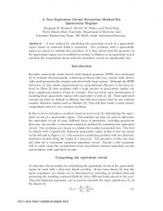
Fig. 3. Example extraction of pad capacitances for GaAs- and InP-HBTs using ( ), variation of junction capacitance with reverse bias [4]. GaAs-HBT: C C ( ); and InP-HBT: C (diamonds), C (o).
1
r
Fig. 2. Hybrid-� small-signal equivalent circuit of the HBT. The dashed box denotes the intrinsic bias-dependent part.
values of the elements removed from the circuit would increase the error in the extracted values of the internal circuit elements. Therefore the outer elements of the equivalent circuit must be extracted very accurately in order to obtain a good equivalent circuit. This paper first gives a description of the new method for determining the pad capacitances. Secondly, the derivation of equations for modeling the intrinsic device at each measured frequency point is given, before outlining the entire extraction procedure. A presentation and discussion of extraction results for InP/GaInAs HBTs conclude the paper. A short section giving approximate, but robust extraction equations for some intrinsic elements is included for comparison purposes.
II. ANALYSIS This section gives an analysis of the coplanar environment in which the device is characterized. It also gives a complete analysis for the T-topology. The T-topology, being directly related to device physics, allows checking of the physical relevance of the extracted parameters, and hence is not only useful for circuit design, but also for device optimization and technology development. The hybrid- model is included for completeness, and since it is useful in large-signal modeling [14]. A. Pad Capacitances The complete lumped-element equivalent circuit for the HBT appears in Figs. 1 and 2. This circuit includes all of the parasitic elements as well as the internal HBT equivalent circuit elements. As seen in the figures, the first step in the extraction and . An is the removal of the two pad capacitances open test structure [13] and variation of reverse bias across both the HBT junctions [4] have been suggested for determining the pad capacitance values. We, as well as other authors, have found these methods to be inaccurate [17], [18]. Measurement of the test structure assumes an open shunt stub for the complete pad structure while under active operation of the device a substantial part of the pad acts as a shorted transmission line, which, for the short pad lengths, is better modeled by a series inductance.
Fig. 4. The through test fixture and its lumped-elements equivalent circuit. The points touched by the RF coplanar probes are marked by arrow heads.
Therefore, the open test structure may overestimate the pad capacitance. In off-state capacitance measurements, on the other hand, a separation of the pad capacitance from the internal device capacitance is difficult [18]. This is demonstrated in Fig. 3 for a singlefinger GaInP/GaAs-HBT and a InP/GaInAs HBT. In case of the GaAs-HBT, the main problem lies in the large values of the measured capacitances. The pad capacitances are given by the small offset that occurs in addition to the pn-junction’s capacitances. Thereby, small changes in the other parameters lead to large relative errors in these capacitances. This is demonstrated in Fig. 3. The total base-collector capacitance can be fit well fF (solid lines) or (dashed lines). yielding is For the base–emitter capacitance, only a fit yielding shown. In the case of high-speed InP HBTs the narrow collector and emitter regions are fully depleted even at positive voltages, and the measured capacitances turn out to be constant. Hence, the assumption of bias-dependent intrinsic capacitance and constant pad capacitance is not valid. We suggest using measurements on a through test fixture as shown in Fig. 4 to extract the pad capacitances. In this structure, a short transmission line between the base and the collector pads replaces the active device. Therefore, the lines conducting current when an active device is connected also conduct current in the test fixture. The lumped-element equivalent circuit for the test fixture is also shown in the figure. The model consists of two capacitances for the open shunt stubs to the left of the left probe and to the right of the right probe and an inductance for the transmission line section between the probes.
2806
Fig. 5. Measured inductance L 50-MHz–100-GHz frequency range.
IEEE TRANSACTIONS ON MICROWAVE THEORY AND TECHNIQUES, VOL. 50, NO. 12, DECEMBER 2002
of the through test fixture over the
From the -parameters of the assumed model for the test fixture the value of the inductance can be found using the following expression: (1) The inductance extracted from S-parameter measurements of a through test fixture using (1) is shown in Fig. 5. As seen in the figure, the section between the probe tips can be approximated by a lumped value of inductance. For frequencies up to 60 GHz, is approximately 132 pH. As the frequency the value of decreases because of the skin effect. At rises, the value of drops to 110 pH. a frequency of 100 GHz, the value of can be found by examining the The pad capacitance , which should give the resonance imaginary part of condition for the LC model as (2) This function which is shown in Fig. 6 exhibits a resonance at . The resonance of the measured test fixture from is at a frequency of 89.5 GHz. Using the value for is found to be (1) at the resonance frequency, the value of 25 fF. is An alternative expression for
Fig. 6. Measured (1=! )Im (1=y ) data points. A distinct resonance can be observed. The continuous line was calculated from the lumped-elements circuit, assumed lossless.
equivalent circuit. For an accurate extraction, the RF probes should be placed very accurately on the pads. Any displacement of the probes can result in a substantial change of the parasitic inductance. In the setup used in this study, the parasitic inductance was found to be anywhere between 20–80 pH depending on the placement of the probes. Note that the length of the through test-fixture is approximately twice the length of each pad section for the actual transistor test pads, and therefore the lumped-element model is even more valid for the actual pad structure. The model and fitting extraction results also indicate that capacitive coupling between , should be located across the input and output ports, i.e., the actual device as shown in Figs. 1 and 2, and not across the pad structure as is often done, and, finally, for comparison purposes, the open test structure gives values of pad capacitances that are about 30% higher than those extracted here. B. Intrinsic Device The HBT T-topology equivalent circuit is shown in Fig. 1, with the intrinsic bias-dependent part shown within the dashed , , , , box. The internal T-network comprising , and can be expressed in -parameters as follows:
(4) (3) as that found using Equation (3) gives the same value for the equation for resonance, i.e., (2), and this confirms the validity of the model. Equation (3) can be used to find pad capacitances in measurement systems with a limited frequency range. using the resonance frequency of A similar calculation for yields a value of 24.5 fF for the second pad capacitance. The measurement of the through fixture not only gives accurate values for the capacitances but the fit to the lumped-element model also validates the model used for the pads in the HBT
where (5) (6) and (7) is the common-base high-frequency current gain. is the dc current gain, essentially models the collector transit time,
SHEINMAN et al.: PEELING ALGORITHM FOR EXTRACTION OF THE HBT SMALL-SIGNAL EQUIVALENT CIRCUIT
2807
whereas models the base transit time as well as the time constants due to the charging of the internal HBT capacitances. From (4)–(7), it follows that
The time constants and are calculated as follows. From (7) and (13), taking the reciprocal of the modulus of (7) and squaring both sides of the equation gives
(8)
(19)
(9)
(11)
vs. should from which it is clear that plotting -intercept gives and the give a linear graph. The and hence and can be determined, gradient gives and, finally, is calculated using
(12)
(20)
(10)
and C. Hybrid- Model (13) Note that
may also be computed using (14)
are the -parameters of the complete intrinsic equivawhere lent circuit. Simple algebraic manipulations show that this equation and (13) for are, in fact, completely identical. Now consider the -parameters of the intrinsic circuit, [ ]. gives De-embedding
where [ ] corresponds to . ] gives the -parameters of the internal The inverse of [ T-network as (15) with and Since (4) and (15) are equal, the intrinsic base resistance [see (8)] can be expressed as
where
(16) and, therefore, we can write (17) from which
is easily determined as (18)
where
.
and A similar analysis yields the same equations for for the hybrid- small-signal equivalent circuit. The equations for extracting the other intrinsic equivalent circuit parameters are identical to those given in [13]. III. PARAMETER EXTRACTION The preceding section has outlined a method for obtaining the pad capacitances and the intrinsic HBT using exact formulae. The extraction process starts by determining the pad capaciand using the through test structure. The series tances parasitic elements, i.e., , , , , , and , are determined from the open-collector measurements as has been done by many other authors, e.g., [4], [6], [17]. Note, however, that and from open collector measurede-embedding of ments is important for an accurate extraction of these elements. The series emitter resistance may also be extracted by the method proposed by Maas [5] which considers the variation of with emitter current. is essentially constant is estimated in the low-frequency range. The capacitance from an open test structure, but since it is small an estimate using , the device geometry should be adequate. The capacitance which models the overlapping area of the emitter runners and the collect mesa, is estimated from device geometry. For devices may be neglected. with an airbridge contact to the emitter, and The extraction procedure proceeds as follows. First, are peeled off. Next, , , and are removed, before and . Finally, , and are removed. peeling off The parasitic capacitances are de-embedded from -parameters, whereas the inductances and resistances from -parameters. Once all the parasitic elements are peeled off from the equivalent circuit, one is left only with measured parameters of the is computed using (18) and also intrinsic device. Next, peeled off. All other intrinsic parameters are then calculated are evaluated using using (8)–(13). The transit times and (19) and (20). A key advantage of calculating each individual element at each measured frequency is that the quality of the extraction can also be checked by looking at any frequency dependence exhibited by the elements. The linear graph used for deand the transit times also assists in further checks termining on the quality of the extraction.
2808
IEEE TRANSACTIONS ON MICROWAVE THEORY AND TECHNIQUES, VOL. 50, NO. 12, DECEMBER 2002
TABLE I EXTRACTED EXTRINSIC ELEMENTS. C ’S IN FEMTOFARADS, L’S PICOHENRYS, AND R’S IN OHMS
IN
TABLE II EXTRACTED INTRINSIC ELEMENTS AT V = 1:5 V I = 8:7 mA. C ’S IN FEMTOFARADS, R’S IN OHMS, AND � IN PICOSECONDS
Fig. 8. Extracted R , R and R at each measured frequency up to 100 GHz. V = 1:5 V, I = 8:7 mA. Arrows point to regions used to extract elements values. R i was extracted using [19].
Fig. 7. Extracted C , C , and � at each measured frequency up to 100 GHz. V = 1:5 V, I = 8:7 mA. The dashed lines show the average values of the elements.
Fig. 9. Measured (-) & simulated (1) S-parameters for the 1 2 10 InP/GaInAs HBT up to 100 GHz. V = 1:5 V, I = 8:7 mA.
IV. RESULTS AND DISCUSSION The outlined extraction procedure has been used to extract the parameters of InP/GaInAs HBTs (emitter area 1 10 m ) fabricated in-house at the Technion–Israel Institute of Technology, Haifa, Israel, and which are designed for the millimeter-wave GHz). A frequency-independent range ( is a good indication that the base–collector capacitance parasitic elements are accurate, and that the overall extraction is good. This capacitance is relatively independent to errors in emitter resistance and inductance, but sensitive to the other pardramatically influence extracted asitic elements. Errors in , and . The intrinsic base resistance values of is by far the most sensitive element in the extraction procedure, and a frequency-independent value is a sure sign of an excellent extraction. Tables I and II show the extracted equivalent-circuit elements. As an example, Figs. 7 and 8 show the frequency (in)dependence of some intrinsic elements over the entire measured frequency range. S-parameter fits are shown in Figs. 9 and 10, re-
Fig. 10. Measured (-) & simulated (1) S-parameters for the 1 2 10 InP/GaInAs HBT up to 100 GHz. V = 1:5 V, I = 8:7 mA.
spectively. The errors in the otherwise excellent fits may be atand tributed to some frequency dependence still shown by
SHEINMAN et al.: PEELING ALGORITHM FOR EXTRACTION OF THE HBT SMALL-SIGNAL EQUIVALENT CIRCUIT
2809
and the intrinsic base resistance
TABLE III DEVICE GEOMETRY, EXTRACTED BASE–COLLECTOR CAPACITANCES, C AND C FOR InP/GaInAs HBT IN THE ACTIVE REGION
approximated by [19]
(23) at high frequencies, and, finally, the dynamic emitter resistance by at low frequencies. REFERENCES
(see Fig. 8), which indicates existence of residual errors in some parasitic elements. The errors may also be attributed to the pad inductances which show a frequency dependence in the high-frequency range arising from skin effect. Using synthetic data, the influence of errors in the parasitics on the intrinsic elements was observed in terms of their variation is best with frequency. For instance, the output resistance taken from the lower frequency range (see Fig. 8 for actual extraction) since small errors in the parasitic elements cause it to fluctuate much at higher frequencies. The base–emitter junction cannot be distinguished from the base transit capacitance time and its extraction remains difficult. and for 3 10 and 4 10 The extracted values of devices are shown in Table III, and these agree well with the expected geometric ratio of the emitter mesa area to the (base mesa area–emitter mesa area). V. CONCLUSION A method for determining parasitic pad capacitances using a through test structure has been described. Exact equations for modeling of the intrinsic HBT have also been presented. Small-signal modeling of HBTs is reduced to an accurate determination of the parasitic element values. Extraction results on measurements up to 100 GHz show that the new formulation can be used for reliable and physically meaningful modeling of HBT’s. The results also demonstrate that an accurately determined lumped-element equivalent circuit can be used in the millimeter-wave range as well. APPENDIX SOME USEFUL EQUATIONS The modeling concept presented in this paper gives good small-signal models, and this is indirectly confirmed by frequency independence of the intrinsic elements. This section, nonetheless, gives some robust approximate equations which can be used to give a first-hand indication of some intrinsic elements. The equations are valid for the intrinsic equivalent circuit, i.e., measured data which is de-embedded of all parasitics. The sum of the base-collector capacitances may be approximated from [7], [8] (21) (22)
[1] E. Wasige, B. Sheinman, V. Sidorov, S. Cohen, and D. Ritter, “An analytic expression for the HBT extrinsic base-collector capacitance derived from S-parameter measurements,” in IEEE MTT-S Int. Microwave Symp. Dig., 2002, pp. 733–736. [2] M. Rudolph, R. Doerner, and P. Heymann, “Direct extraction of HBT equivalent-circuit elements,” IEEE Trans. Microwave Theory Tech., vol. 47, pp. 82–84, Jan. 1999. [3] G. Dambrine, A. Cappy, F. Heliodore, and E. Playez, “A new method for determining the FET small-signal equivalent circuit,” IEEE Trans. Microwave Theory Tech., vol. 36, pp. 1151–1159, July 1988. [4] Y. Gobert, P. J. Tasker, and K. H. Bachem, “A physical, yet simple, small-signal equivalent circuit for the heterojunction bipolar transistor,” IEEE Trans. Microwave Theory Tech., vol. 45, pp. 149–153, Jan. 1997. [5] S. A. Maas and D. Tait, “Parameter extraction method for heterojunction bipolar transistors,” IEEE Microwave Guided Wave Lett., vol. 2, pp. 502–504, Dec. 1992. [6] C.-J. Wei and J. C. M. Hwang, “Direct extraction of equivalent circuit paramters for heterojunction bipolar transistors,” IEEE Trans. Microwave Theory Tech., vol. 43, pp. 2035–2040, Sept. 1995. [7] S. J. Spiegel, D. Ritter, R. A. Hamm, A. Feygenson, and P. R. Smith, “Extraction of the InP/GaInAs heterojunction bipolar transistor smallsignal equivalent circuit,” IEEE Trans. Microwave Theory Tech., vol. 42, pp. 1059–1064, June 1995. [8] D. Peters, W. Daumann, W. Brockerhoff, R. Reuter, E. Koenig, and F. J. Tegude, “Direct calculation of the HBT small-signal equivalent circuit with special emphasis to the feedback capacitance,” in Proc. European Microwave Conf., vol. 2, 1995, pp. 1032–1036. [9] M. Sotoodeh, L. Sozzi, A. Vinay, A. Khalid, Z. Hu, A. Rezazadeh, and R. Mennozzi, “Stepping toward standard methods of small-signal parameter extraction for HBT’s,” IEEE Trans. Microwave Theory Tech., vol. 47, pp. 1139–1151, June 2000. [10] B. Li, S. Prasad, L.-W. Yang, and S. C. Wang, “A semianalytical parameter-extraction procedure for HBT equivalent circuit,” IEEE Trans. Microwave Theory Tech., vol. 46, pp. 1427–1435, Oct. 1998. [11] U. Schaper and B. Holzapfl, “Analytical parameter extraction of the HBT equivalent circuit with T-like topology from measured S-parameters,” IEEE Trans. Microwave Theory Tech., vol. 43, pp. 493–498, Mar. 1995. [12] D. R. Pehlke and D. Pavlidis, “Evaluation of the factors determining HBT high-frequency performance by direct analysis of S-parameter data,” IEEE Trans. Microwave Theory Tech., vol. 40, pp. 1139–1151, Dec. 1992. [13] D. Costa, W. U. Liu, and J. S. Harris, “Direct extraction of the AlGaAs/GaAs heterojunction bipolar transistor small-signal equivalent circuit,” IEEE Trans. Electron Devices, vol. 38, pp. 2018–2024, Sept. 1991. [14] D. A. Teeter and W. R. Curtice, “Comparison of hybrid Pi and Tee HBT circuit topologies and their relationship to large signal modeling,” in IEEE MTT-S Int. Microwave Symp. Dig., 1997, pp. 375–378. [15] T. S. Horng, J. M. Hu, and H. H. Huang, “An extrinsic-inductance independent approach for direct extraction of HBT intrinsic circuit parameters,” IEEE Trans. Microwave Theory Tech., vol. 49, pp. 1139–1151, Dec. 2001. [16] Y. Suh, E. Seok, J.-H. Shin, B. Kim, D. Heo, A. Raghavan, and J. Laskar, “Direct extraction method for internal equivalent circuit parameters of the HBT small-signal hybrid-� model,” in IEEE MTT-S Int. Microwave Symp. Dig., 2000, pp. 1401–1404. [17] S. Bousnina, P. Mandeville, A. B. Kouki, R. Surridge, and F. M. Ghannouchi, “Direct parameter-extraction method for HBT small-signal model,” IEEE Trans. Microwave Theory Tech., vol. 50, pp. 529–536, Feb. 2002. [18] A. Samelis and D. Pavlidis, “DC to high-frequency HBT-model parameter evaluation using impedance block conditioned optimization,” IEEE Trans. Microwave Theory Tech., vol. 45, pp. 886–897, June 1997.
2810
IEEE TRANSACTIONS ON MICROWAVE THEORY AND TECHNIQUES, VOL. 50, NO. 12, DECEMBER 2002
[19] F. Lenk and M. Rudolph, “New extraction algorithm for GaAs-HBT’s with low intrinsic base resistance,” in IEEE MTT-S Int. Microwave Symp. Dig., 2002, pp. 725–728. [20] W. Liu, Fundamentals of III-V Devices: HBT’s, MESFET’s, and HFETs/HEMT’s. New York: Wiley, 1999.
Benny Sheinman was born in Israel in 1969. He received the B.Sc. and M.Sc. degrees in electrical engineering in 1991 and 1998, respectively, from the Technion–Israel Institute of Technology, Haifa, Israel, where he is currently working toward the Ph.D degree in electrical engineering. His research focuses on design, growth, and modeling of InP-based HBTs and on microwave optoelectronic circuits.
Edward Wasige recieved the B.Sc.(Eng) degree from the University of Nairobi, Nairobi, Kenya, in 1988, the M.Sc.(Eng). degree from the University of Liverpool, Liverpool, U.K., in 1990, and the Dr.-Ing. degree from the University of Kassel, Kassel, Germany, in 1999, all in electrical engineering. In 1988, he became a member of staff in the Department of Electrical and Communications Engineering, Moi University, Eldoret, Kenya, where he later became a Senior Lecturer. He then visited the Technion–Israel Institute of Technology, Haifa, Israel, as a UNESCO Postdoctoral Fellow. He is currently with the Department of Electronics and Electrical Engineering, University of Glasgow, Glasgow, U.K. His current interests are in measurement-based modeling of ultrafast devices (HBTs, RTDs, and FETs) and associated circuit design for applications in optical as well as wireless communications.
Matthias Rudolph (M’99) was born in Stuttgart, Germany, in 1969. He received the Dipl.-Ing. degree in electrical engineering from the Technische Universität Berlin, Berlin, Germany, in 1996, and the Dr.-Ing. degree from the Technische Universität Darmstadt, Darmstadt, Germany, in 2001. In 1996, he joined the Ferdinand-Braun-Institut für Höchstfrequenztechnik, Berlin, Germany, where he currently is a Research Scientist. His research focuses on characterization and modeling of FETs and HBTs and on MMIC design.
Ralf Doerner (M’97) was born in Neindorf, Germany, in 1965. He received the Dipl.-Ing. degree in communications engineering from the Technische Universität Ilmenau, Ilmenau, Germany, in 1990. Since 1989, he has been working on microwave measuring techniques. In 1992, he joined the Ferdinand-Braun-Institut für Höchstfrequenztechnik, Berlin, Germany. His current research is focused on calibration problems in on-wafer millimeter-wave measurements of active and passive devices and circuits and on nonlinear characterization of microwave power transistors.
Victor Sidorov received the M. Sc. (Honors) degree in chemistry from Voronezh University, Voronezh, Russia, in 1985. Since 1995, he has been a Senior Research Assistant in the Microelectronics Research Center of the Technion–Israel Institute of Technology, Haifa, Israel, with primary responsibilities involve microwave and optoelectronic devices and circuits manufacturing based on III-V semiconductors processing. Prior to this, he held an Engineer–Researcher position at Mizur Micromechanics Technologies Ltd., where he was responsible for microsensors manufacturing and micromachinning. His current research interests are III-V semiconductor surface coatings and passivation.
Shimon Cohen received the practical engineering diploma in electrooptics from the Technion–Israel Institute of Technology, Haifa, Israel, in 1981. Since 1981, he has been working on epitaxial crystal growth at the Technion–Israel Institute of Technology. His work has included growth of hydrogenated amorphus silicon. Since 1991, he has been working on growth of InP-related materials using metal–organic molecular beam epitaxy . His main interests are physics and technology of epitaxial crystal growth.
Dan Ritter received the B.Sc., M.Sc., and Ph.D. degrees in electrical engineering from the Technion–Israel Institute of Technology, Haifa, Israel, in 1981, 1984, and 1989, respectively. He carried out postdoctoral research during three years at AT&T Bell Laboratories, Murray Hill, NJ. In 1992, he joined the Electrical Engineering Department of the Technion–Israel Institute of Technology, Haifa, Israel, where he is currently an Associate Professor. His main research interests are physics and modeling of indium-phosphide-based devices. His group has been using the metalorganic molecular beam epitaxy method to grow the epitaxial layers. The focus of his current activity is heterojunction bipolar transistors.