OpenGL and Direct3D contain many elements irrelevant to GPU computation, and failure to ensure that such elements are set properly can lead to confusing ...
A Performance-Oriented Data Parallel Virtual Machine for GPUs Mark Segal
Mark Peercy ATI Technologies, Inc.
Abstract Existing GPU programming interfaces require that applications employ a graphics-centric programming model exported by a device driver tuned for real-time graphics and games. This programming model impedes development of non-graphics applications by hiding hardware resources behind its graphics-oriented interface. We present a virtual machine abstraction for GPUs that provides policy-free, low-level access to the hardware and is designed for high-performance, data-parallel applications.
1. Overview GPUs make an attractive platform for numerically-intensive calculation because of their inexpensive high-performance SIMD arrays originally conceived to shade fragments. These arrays consist of up to several dozen processors connected to a high-bandwidth, latency-hiding memory system [ATI05]. This combination can outperform CPUs, sometimes by more than an order of magnitude, on numerically-intensive applications. Examples of algorithms that have been implemented with success on GPUs range from collision detection and response to medical image segmentation. Such implementations, unfortunately, must rely on either OpenGL [SA04] or Direct3D [Mic06] to access the hardware (or one of the many interfaces layered on top of these which must ultimately do the same). OpenGL and Direct3D contain many elements irrelevant to GPU computation, and failure to ensure that such elements are set properly can lead to confusing program bugs. More significant is that these APIs, by design, hide architectural details that are of importance to GPU programmers. As part of this hiding, graphics drivers make policy decisions, such as where data reside in memory and when they are copied, that may rob performance from a non-graphics application. Such a loss in performance undermines the motivation to implement a technique on the GPU in the first place. We present a new virtual machine abstraction for GPUs that hides irrelevant graphics components and exposes the GPU as a data-parallel processor array and a memory controller, fed by a simple command processor. This model c
2006 ATI Technologies, Inc.
presents a thin interface to the hardware, requiring practically no management on the CPU. The programmer makes decisions, for instance, about when and how data are copied. These capabilities allow programmers to obtain the maximum performance available from the hardware. 2. Related Work Previous work on programming interfaces specifically for GPU computation has focused on providing a layer above D3D or OpenGL. Such systems include Brook [Be04] and Sh [Me04], and even Cg [FK03]. These systems provide a higher-level abstraction designed to present a particular programming model that happens to fit GPUs well but may also be applicable to other hardware, such as CPUs. Our approach is to present the capabilities of modern GPUs with as little interference as possible and without assuming a graphics usage pattern, while maintaining an abstraction that can span GPU architectures. Higher-level abstractions can take advantage of the capabilities provided by this low-level interface, providing higher performance than would otherwise be achievable. 3. The Data Parallel Virtual Machine (DPVM) The data parallel processing array (fragment engines) in a GPU is embedded in a graphics pipeline that includes such components as vertex processing, rasterization, texture filtering, depth buffering, blending, and anti-aliasing. The graphics pipeline, in turn, is controlled by a harness that couples
2
M. Segal & M. Peercy / A Performance-Oriented Data Parallel Virtual Machine for GPUs
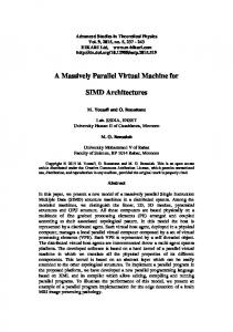
the GPU to a computer system through a system bus. This harness dispatches work requests, in the form of command buffers, to the graphics pipeline and services read and write requests to external memory. In modern GPUs, the control harness architecture is reasonably uniform from one GPU to another. The graphics pipeline and data parallel processing array, however, remain device-specific. Our platform, the Data Parallel Virtual Machine (DPVM), provides a device-independent control infrastructure (command buffer format and memory abstraction) that manages device-dependent binary executables for a given data parallel array. The DPVM control need not interpret this program data; it simply allows the array to access it [Khr05]. All other components of the graphics pipeline are hidden and managed by the DPVM implementation. This keeps the interface small and simplifies implementation on diverse GPU architectures. The DPVM splits the problem of computation on the GPU into one of code generation, which is device-dependent, and program execution, which, ideally, is device-independent. Code generation happens outside the DPVM. Naturally, with this model, a program can be made device-independent by compiling it from a higher-level language. A benefit of the virtual machine model is that an implementation can readily coexist with graphics drivers. A game, for example, could use a single GPU for both graphics and physical simulation: OpenGL or Direct3D can be used for the graphics rendering, while the DPVM can be used for computation. The same memory is accessible by both the graphics APIs and the DPVM. Additionally, multiple virtual machines can be instantiated on a single GPU or across more than one GPU. 3.1. DPVM Components The Data Parallel Virtual Machine presents the GPU as three major components: a command processor, a memory controller, and a data-parallel processor array (see Figure 1).
Figure 1: Block diagram of the DPVM.
pair within a domain set by the setDomain instruction. This is the equivalent of, in graphics, drawing a screen-aligned rectangle and having the fragment processors shade each of the resulting fragments. The DPVM provides the ability to skip processing for certain (x,y) points based on a conditional value associated with all points. This value is compared with the corresponding value stored in memory in a conditional buffer (a depth buffer, in graphics). A particular (x,y) point is processed only if the comparison succeeds. Thus, this feature provides a form of conditional execution. The comparison used is set using a DPVM command, as is the location of the conditional buffer in memory. Finally, the command processor is responsible for some DPVM system functionality. The waitForIdle command blocks the execution of subsequent commands in the buffer until all previous commands have taken effect. The PerfCounters commands allow setup and reading of basic performance counters: total GPU cycles and total non-idle clocks since last counter reset. 3.1.2. Memory Controller
The command processor accepts commands packaged by an application. The programmer sends these commands to the DPVM by filling a buffer with them and then calling a submit function to process them. The DPVM commands are listed in Table 1. Each command is a group of 32-bit words. The first word is the opcode of the command; subsequent words are parameters to the command. Together, the commands provide relatively direct control over the data parallel array and the memory controller.
In contrast to textures and render targets, the DPVM presents graphics memory directly to the application. Command buffers, program instructions, constants, and inputs and outputs are stored in GPU (video) or PCI-Express (CPU memory addressable by the GPU) memory locations specified by the application. The application also specifies input and output memory formats to the memory controller (before running a program that uses those inputs and outputs). Thus, the programmer must ensure that memory is being interpreted in the proper format, but an application may reinterpret values written in one format (e.g. a 4 component array) in another (e.g. a 1 component array of 4 times the length). Such casting can allow data reinterpretation without copying.
The command processor is responsible for scheduling processors to run when it receives a startProgram command. In the simple case, the program is run for every (x,y) index
Modern GPUs use tiling, in which values that are addressed linearly are actually stored as tightly packed small arrays (this is done to improve memory efficiency and cache
3.1.1. Command Processor
c
2006 ATI Technologies, Inc.
M. Segal & M. Peercy / A Performance-Oriented Data Parallel Virtual Machine for GPUs
Command setInpAddress [i, a, f, n]
setOutFormat [o, a, f, n]
setConstAddress [a] SetCondOutAddress [a, f]
SetProgramAddress [a] invInpCache invConstCache invCondOutCache flushOutCache flushCondOutCache SetCondTest [t] SetDomain [x0, y0, x1, y1]
startProgram waitForIdle resetPerfCounters ReadPerfCounters [a]
Description Set base address of input i to a, with format f and n components Set base address of output o to a, with format f and n components Set constant base address to a Set conditional output buffer base address to a with format f Set program base address to a Invalidate input caches Invalidate constant cache Invalidate cond. output cache Flush output cache Flush conditional output cache Set the conditional test to t Rectangle with corners (x0, y0) and (x1, y1) defines points to process Run DPA program over domain Wait until previous commands complete Reset performance counters Write performance counter values starting at address a
Table 1: Summary of DPVM commands.
behavior when working with 2D arrays). The DPVM exposes such tiling. The details of a how values are placed in memory under a particular tiled format may be GPUspecific. But an application may specify a tiled format without knowledge of how values are packed in memory for that format, and access the data by running a program that copies tiled to untiled. Additionally, exposing the tiling format makes intermediate results interpretable, simplifying debugging. The DPVM specifies data formats for inputs and outputs that consist of one, two, or four components per element. Only formats consisting of 32-bit floating-point values are currently exposed, even though the underlying hardware supports many more (such as fixed-point formats of 4, 8, or 16 bits per component). This restriction simplifies the c
2006 ATI Technologies, Inc.
3
DPVM, yet provides sufficient functionality for the majority of data-parallel applications. The memory controller uses caches to improve its performance. The size and structure of these caches is unspecified, but the programmer is responsible for flushing output caches and invalidating input caches when required (as when changing an address). Thus, the programmer is in control of these potentially expensive operations, rather than a graphics driver. 3.2. Data Parallel Array The data parallel array (DPA) is the computational element of the DPVM. It can access some number of inputs (textures) and can write some number of outputs (render targets and conditional buffer). Beyond this, the details of the processing capabilities of the array are machine-specific. The DPVM specifies an application binary interface (ABI) that exposes the native instruction set of the DPA (fragment) processors. The DPVM implementation includes a program loader that extracts binary executables from objects in the Executable and Linking Format (ELF). A programmer specifies where in memory, with a command in the command buffer, these ELF modules are located and when they are to be used by invalidating the instruction cache. Exposing the native instruction set of the data parallel array brings several benefits. First, once a program is compiled (or written directly in assembly language) it is immune to compiler changes resulting from driver updates that might affect its performance. Further, access to machine language simplifies debugging and performance tuning. Finally, if a compiler is failing to produce code of the desired efficiency, the programmer can always revert to assembly language. 4. DPVM Interface The DPVM interface consists of four function calls into a library. OpenConnection and CloseConnection, respectively, create and destroy instances of the DPVM. SubmitCommandBuffer submits the specified command buffer (of specified length) to the DPVM, returning an ID for that buffer, and CommandBufferConsumed tells whether the buffer with given ID has been completely scanned by the GPU, allowing its memory to be overwritten. OpenConnection returns a structure that contains information about the GPU’s memory layout. Included are the base addresses and sizes of GPU memory, as well as PCI-E memory, cached and uncached on the CPU. For GPU memory, GPU addresses are returned; for CPU memory, both GPU and CPU addresses are returned. Taken together, this information describes the GPU memory available to the application. All other control of the DPVM is achieved by submitting commands. The command buffer was chosen as the method
4
M. Segal & M. Peercy / A Performance-Oriented Data Parallel Virtual Machine for GPUs
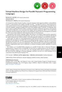
of control because the underlying hardware also works by being sent command buffers. Error checking can be added to the command interpreter on the CPU, but otherwise the correspondence between DPVM commands and hardware commands is nearly one-to-one. 5. Implementation We have implemented a DPVM on the ATI X1K architecture using low-level, internal, components from ATI’s OpenGL driver. We also developed an assembler/disassembler for the X1K DPA processor so that we could program the processor in its machine language. And we developed a compiler that generates X1K DPA ELF files from programs written in HLSL and Direct3D PS 3.0. 5.1. ATI X1K processor While the instruction set architecture of the processor array in a DPVM instantiation is GPU-specific, for concreteness we briefly describe the characteristics of the DPA processors found in the ATI X1K architecture. An individual processor (Figure 2) comprises a read/write register file for intermediate results, a read-only constant file (values of which can be written by the CPU before program execution), an ALU capable of simultaneously operating on a vector (3-tuple) and a scalar, an input unit that issues memory read requests, an output unit that issues memory write requests, and an instruction sequencer.
Name MAD DP3 DP4 D2A MIN MAX CND CMP FRC SOP
Description A*B + C A[0]*B[0]+A[1]*B[1]+A[2]*B[2] A[0]*B[0]+A[1]*B[1]+A[2]*B[2]+A[3]*B[3] A[0]*B[0]+A[1]*B[1]+C[2] min(A,B) max(A,B) C>0.5 ? A : B C>=0 ? A : B fractional part of A Replicate scalar math result Table 2: Vector ALU operations.
Name MAD VDP MIN MAX CND CMP FRC EX2 LN2 RCP RSQ SIN COS
Description A*B + C DP3, DP4, or D2A vector op result min(A,B) max(A,B) C>0.5 ? A : B C>=0 ? A : B fractional part of A 2A log2 (A) 1/A 1/sqrt(A) sin(A) cos(A)
Table 3: Scalar ALU operations.
Figure 2: Block diagram of an X1K DPA processor.
The vector and scalar components of the ALU each consist of two parts. The main portion of each ALU performs an operation on its three inputs (A, B, C) in a single clock cycle. The vector and scalar operations are summarized in Tables 2 and 3, respectively. The second portion can add or subtract inputs from one another before they are presented to the main ALU. All data values are IEEE floating-point single-precision, and calculations conform to the IEEE standard with the following exceptions: rounding cannot be controlled; denorms, except in certain pass-through operations, are treated as 0; 1/x is accurate to 1 lsb; and the trig and power functions have varying accuracy. Each register and constant consists of 4 values. The vector and scalar units each select registers or constants for each input independently. Once registers and constants are selected, any individual components within the selections may
be routed to any of the vector component or scalar inputs. The result of an ALU operation may be sent to a register, the output, or both; masking may be specified to cause only certain of the 4 components to actually be written. In addition, predication based on a previous ALU result is available to enable data-dependent conditional writing of a register. The ATI X1K DPA may submit a request for a memory read to the memory controller by passing it an (i,j) index pair. This index pair is used to retrieve data within a 2D array whose dimensions and format are set in the command buffer. The value(s) read by the memory controller are placed in a return register specified in the input instruction; this placement may include rearrangement or duplication of the components obtained from memory. The DPA may also submit a request to the memory controller to write memory by passing it the (x,y) index pair identifying the current processor, and specifying one of four outputs. Each output holds 4 values, specified as the result of an ALU instruction. In addition, a value can be output by a processor to the conditional output buffer. The sequencer reads instructions from memory, decodes them, and causes each instruction to be executed. Each inc
2006 ATI Technologies, Inc.
M. Segal & M. Peercy / A Performance-Oriented Data Parallel Virtual Machine for GPUs
struction comprises 6 32-bit words, and there can be up to 512 of them. There are three kinds of instructions: ALU, input read, and flow control. The operation of ALU and input read instructions has already been described. Flow control instructions allow conditional branching based on conditions generated by the ALU as well as the value of constant flags, looping using dedicated integer loop limit registers (set by the CPU only), and subroutine calls. Nested conditionals, loops, and subroutine calls are allowed up to 4 deep.
SetInstFormat: progGPU InvalidateInstCache SetDomain: 0, 0, 511, 511 StartProgram
6. Usage Example
while (CommandBufferConsumed(id) == 0);
Consider a simple DPA program to copy input to output. The X1K assembly language for such a program consists of just two instructions: TEX r1 r0 in0 MAD out0 r1 1 0
mad out0 r1 1 0
The first instruction says to use register r0 as the (i,j) index to obtain the value stored in input 0 (only the first two components of r0 are used); the result is placed in r1. (In the X1K DPA processor, when a program is started, the (x,y) values of the point being processed are placed in the first two components of r0). The second instruction has two parts: the uppercase MAD controls the vector unit, processing the first three components, and the lowercase one controls the scalar unit. Each multiplies the corresponding values in r1 by 1 and adds zero to them, placing the results in output 0. To set up the DPVM so that it can execute this program, a connection is opened to the DPVM: info = uint32 uint32 uint32 uint32 uint32 uint32 uint32
OpenConnection(); cbufGPU = info.baseAddressPCIE; cbufCPU = info.CPUbaseAddressPCIE; progGPU = cbufGPU + 2048; progCPU = cbufCPU + 2048; inputGPU = progGPU + 2048; inputCPU = progCPU + 2048; outputGPU = info.baseAddressGPU;
This code reserves space in PCI-E memory for a command buffer, program instructions, and input. Both GPU and CPU addresses are derived (the latter are required so the CPU can write data into each of these areas). The last line indicates that the output is to go in GPU memory. Assume the CPU has assembled the DPA program and placed it in its proper location in memory, and that the CPU has initialized the input. If the input and output both have dimensions of 512 x 512, then the following DPVM commands are placed in memory (represented here in a functional shorthand) starting at cbufCPU: FlushOutCache SetOutFormat: 0, outputGPU, FLOAT4\_UNTILED, 512, 512 InvalidateInpCache SetInpFormat: 0, inputGPU, FLOAT4\_UNTILED, 512, 512 c
2006 ATI Technologies, Inc.
5
This command buffer is submitted: id = SubmitCommandBuffer(cbufGPU, length);
Then the application waits for the command buffer to be consumed:
When this while loop terminates, the commands have all been read. If, in addition, the DPA program should have completed running on all (x,y) points, then the submitted command buffer should have a WaitForIdle command appended to it.
7. Experience We have implemented several basic applications using the DPVM, including dense matrix-matrix multiply and 1D FFT. For matrix-matrix multiply, we use block multiplication to reduce the number of redundant reads (thus improving performance) of the input matrix elements as described in [FSH04]. Their method uses a single 4 component output and 2x2 blocking. Our implementation uses all 4 outputs to achieve 4x4 blocking, halving the number of reads. Using this technique, we have been able to achieve performance on an ATI X1900 XTX of 110 Gflops/sec for 512 x 512 matrices. While matrix-matrix multiply is a relatively straightforward algorithm, using the DPVM to implement it provided several advantages that aided development. Using assembly language for the DPA program instead of a higher-level language allowed us to understand the program’s performance clearly, since we directly described the hardware instructions being executed; it also made it simple to try different instruction orderings to determine their effect on performance. The CPU program is short and simple because required computational elements were accessed directly instead of mapping them to graphical constructs provided by OpenGL or D3D. Finally, the ability to read and write matrices in PCI-E memory directly eased debugging, since the CPU can examine the results written by the GPU directly. The FFT implementation is complicated; we will not describe it here. But the same features that helped in the development of the matrix-matrix multiply code were even more helpful in this more complicated case. In addition, the ability to write data in one format and read it in another without copying (Section 3.1.2) proved invaluable in obtaining the maximum performance. On a 1D 4K complex FFT, we obtained performance of 12 Gflops/sec on an ATI X1900 XTX.
6
M. Segal & M. Peercy / A Performance-Oriented Data Parallel Virtual Machine for GPUs
8. Conclusion The DPVM provides a straightforward programming model for data parallel applications. It gives access to essential low-level functionality, yet presents a simplified target more palatable for tool development than the full hardware specification. As a result, developers can focus on compilers, debuggers, and utility libraries that target the dataparallel array of fragment processors without the burden of a graphics-centric driver. This is essential for developing highperformance data parallel applications that use the GPU for computation. In the future, we would like to augment the DPVM with at least some of the GPU capabilities that were left out (described in Section 3) in the interests of expediency and simplicity. Adding some of these features simply amounts to adding commands to control them (examples include the per-pixel operations), while others require more care and perhaps some changes to the DPVM model (vertex processing and rasterization are examples). References [ATI05] ATI R ESEARCH , I NC .: The Radeon X1x00 Programming Guide. www.ati.com, 2005. [Be04] B UCK I., ET AL : Brook for gpus. In Proc. SIGGRAPH ’04 (2004), pp. 777–786. [FK03] F ERNANDO R., K ILGARD M.: The Cg Tutorial: The Definitive Guide to Programmable Real-Time Graphics. Addison-Wesley, 2003. [FSH04] FATAHALIAN K., S UGARMAN J., H ANRAHAN P.: Understanding the efficiency of gpu algorithms for matrix-matrix multiply. In Proc. Graphics Hardware ’05 (2004), pp. 89–94. [Khr05] K HRONOS G ROUP: OpenGL ES 2.0 Specification. www.khronos.org, 2005. [Me04] M C C OOL M., ET AL : Shader algebra. In Proc. SIGGRAPH ’04 (2004), pp. 787–795. [Mic06] M ICROSOFT I.: msdn.microsoft.org, 2006.
Direct3D
Reference.
[SA04] S EGAL M., A KELEY K.: The OpenGL Graphics System: A Specification, Version 2.0. www.opengl.org, 2004.
c
2006 ATI Technologies, Inc.