Hindawi Publishing Corporation Journal of Computer Networks and Communications Volume 2016, Article ID 5191405, 15 pages http://dx.doi.org/10.1155/2016/5191405
Research Article A Persistent Structured Hierarchical Overlay Network to Counter Intentional Churn Attack Ramanpreet Kaur,1,2 Amrit Lal Sangal,1 and Krishan Kumar3 1
Department of Computer Science and Engineering, National Institute of Technology, Jalandhar, Punjab, India Department of Information Technology, Jaypee University of Information Technology, Solan, Himachal Pradesh, India 3 Department of Computer Science and Engineering, Shaheed Bhagat Singh State Technical Campus, Ferozepur, Punjab, India 2
Correspondence should be addressed to Ramanpreet Kaur;
[email protected] Received 23 February 2016; Revised 12 August 2016; Accepted 5 September 2016 Academic Editor: Rui Zhang Copyright © 2016 Ramanpreet Kaur et al. This is an open access article distributed under the Creative Commons Attribution License, which permits unrestricted use, distribution, and reproduction in any medium, provided the original work is properly cited. The increased use of structured overlay network for a variety of applications has attracted a lot of attention from both research community and attackers. However, the structural constraints, open nature (anybody can join and anybody may leave), and unreliability of its participant nodes significantly affect the performance of these applications and make it vulnerable to a variety of attacks such as eclipse, Sybil, and churn. One attack to compromise the service availability in overlay network is intentional churn (join/leave) attack, where a large number of malicious users will join and leave the overlay network so frequently that the entire structure collapses and becomes unavailable. The focus of this paper is to provide a new robust, efficient, and scalable hierarchical overlay architecture that will counter these attacks by providing a structure that can accommodate the fleeting behaviour of nodes without causing much structural inconsistencies. The performance evaluation showed that the proposed architecture has more failure resilience and self-organization as compared to chord based architecture. Experimental results have demonstrated that the effect of failures on an overlay is proportional to the size of failure.
1. Introduction In the past two decades, structured overlay networks have emerged as a suitable architecture for implementation of various content sharing and internet service support system applications. An overlay network is defined as a layer of virtual network topology on the top of physical network, where a large number of users are pooled in order to share their resources and to provide distributed points of service. The significant scale, fault tolerance, and cost advantages of overlay networks make them very popular in the present internet scenario. Although these structures are very efficient and popular, they are not developed by keeping security in mind and are susceptible to many attacks. They can serve as a vehicle for attackers on the internet as they are vulnerable to many attacks because of the fleeting behaviour of nodes forming the overlay network. There are two types of overlay networks available: structured and unstructured overlay networks. The structured
overlay networks impose constraints on the structure of the overlay. So, if a significant number of nodes join and leave the network at an extremely rapid rate the overhead (maintenance messages) associated with this dynamism can become significant, thus degrading the performance of the system. This requirement makes structured overlay network more sensitive to the fleeting behaviour of nodes. The sensitivity of participants serves as a weapon for attackers to launch churn attack in order to bring the entire overlay structure down. An ideal overlay network should be fault-tolerant and self-organized against the dynamic behaviour of nodes (also known as churn). However, the initial design of overlay structures does not take into consideration the notorious fleeting behaviour of their nodes and thus has the limited fault tolerance and self-organization. Security is an important issue that needs to be considered when choosing architecture to design an overlay system. Since overlay nodes are potentially unreliable and expected to behave in malicious ways, thus providing an
2
Journal of Computer Networks and Communications
acceptable level of security in overlay based applications is quite challenging. Till date, researchers [1–8] have uncovered the various security issues in structured overlay networks. The major security issues include eclipse attack (colluding nodes attempt to partition the network) [9–12], Sybil attack (where nodes forge identities) [13–15], and churn attack [6, 16–18]. Although a lot of research has been done on eclipse and Sybil attacks, surprisingly churn induced attacks are not widely studied. Most of the proposed structures [19– 24] guarantee the performance of structured overlays in controlled environments only and do not consider induced dynamics of malicious peers. Although some researchers [25–29] have studied the criticality of peer dynamics and churn induced attacks, none of the proposed work can cope with these attacks without affecting the openness of overlay networks. So, in this paper, we design a new robust structured hierarchical overlay architecture that will counter these attacks by providing a structure that can accommodate the fleeting behaviour of nodes without causing much structural inconsistencies. In this architecture certain nodes (highly stable nodes with always on characteristic) have assigned special roles to manage the arrangement of less stable and new nodes. The proposed architecture is a robust, self-modifying, and scalable structure based on a hierarchical combination of chord and robust m-child family tree with its nodes spread over multiple peers. A peer can be mapped to a node based on hash based uniform mapping. From the above analysis, it is clear that, in a dynamic large scale network, the problem of node dynamicity must be addressed without causing routing inconsistency. In this paper, we propose structured hierarchical overlay architecture by using a super peer concept [30–35]. In the proposed approach, we use a combination of ring and robust m-child family tree and explore the dynamicity handling by localizing the effect of churn attack in subtree and cause minimum structural or routing inconsistencies. The use of robust mchild family tree architecture is powerful not just because it supports key based lookup, but because they work even when the network is highly dynamic with nodes constantly joining and leaving the network. That is, robust m-child family tree structure can handle the churn attack scenario without causing much structural inconsistencies as most updates and structural transformations (new key is always inserted at the leaf node) of robust m-child family trees are limited to the leaves and lower levels of the tree. In the proposed hierarchical design, super peer nodes are selected based on some predefined performance criteria such as performance and reliability. These super peer nodes will serve as a root node for individual m-child family trees and will be arranged in ring architecture according to their peer IDs. As we explain in this paper, the proposed architecture has the following advantages over basic chord architecture: (i) The proposed architecture provides more stability, as dynamic population changes in this architecture have limited interference to a tree rather than to the whole network. So, this architecture provides “isolation of churn” as node join or leave within a tree will not affect the top level chord overlay.
(ii) Most of the available tree structures suffer from lack of redundancy and therefore their structure is sensitive to single node and link failures. In the robust mchild family tree this limitation is overcome by storing additional pointers to parent and uncles along with the child information to make it robust to node and link failures. (iii) The m-child family tree structure ensures that new unreliable node will always join as the leaf node and as we know in the tree topology the effect of failure is much higher for nodes close to the root node. So, our proposed tree structure is robust to churn attack where an attacker will trigger a large number of new nodes to join and leave the overlay in a short time span, because all these nodes irrespective of their node ID values will always join as leaf nodes and minimize the topology changes resulting from the new nodes joining and leaving the overlay. (iv) In order to ensure fault tolerance, each super peer node has a backup node, which periodically pings the super peer and makes checkpoints on its status. The remainder of this paper is organized as follows. Section 2 introduces the basic concepts and the most important contributions in this area. In Section 3, we provide abstract system model and adversarial model. Section 4 introduces our proposed structured hierarchical overlay network model. In Section 5, we discuss the basic algorithms for the proposed overlay architecture. Section 6 outlines the design of our experiments and covers the results and discussions.
2. Background and Related Work In this section, we first introduce the basic concepts to aid the better understanding of our research work. Then, we discuss the important research contributions in the field of robust structured overlay networks that can handle a large fraction of malicious peers that frequently join/leave the overlay network to consume most of the network bandwidth for structure management purposes and make the network unstable. 2.1. Basic Concepts. Before discussing the value of proposed architecture, we first introduce the hierarchical overlay networks and then examine the churn, both as legitimate and as malicious behavior. This section will highlight the need of robust overlay architectures to maintain the health and security of the overlay networks in the face of churn. 2.1.1. Structured Hierarchical Overlay Networks. Structured overlay networks are a self-organized, distributed architecture of a large number of heterogeneous and unreliable machines arranged in a specialized structure to share a set of resources with reasonable performance guarantees. In traditional structured overlay networks all the participants are considered equal in the sense that they share the same set of responsibilities and use the same set of rules for determining the lookup routes for the messages [38]. Searching is one of the most important services provided
Journal of Computer Networks and Communications by the structured overlay networks. The desired features of searching are high quality query results, minimum query overhead, high routing efficiency, and resilience to node failures. Structured overlay networks have poor searching performance in dynamic environments, where nodes join and leave the overlay network frequently. To capture the heterogeneity of overlay participants and to improve the performance and scalability, overlay networks utilize the multiple levels of hierarchy in the form of hierarchical overlay networks. In these architectures, different overlay participants are given different roles (super peers and regular nodes) based on their reliability and capability. Structured hierarchical overlay networks use only structured topology at each level. The main aim behind the use of hierarchical overlay networks is to group the overlay nodes logically and each group then utilizes its intragroup overlay protocol for maintenance and lookup operation. This logical grouping of nodes is done in the top layer overlay network, where one or more nodes have been assigned the responsibility of super nodes and act as the gateway to the next level of nodes. 2.1.2. Churn. The correctness and the performance of structured overlay networks mainly depend on its up to date routing table entries that together form an overlay topology with specific structural constraints (e.g., ring structure in the chord overlay network). But, due to their open nature in the real world, where nodes may join or leave the overlay network at any time, this continuous dynamism of peer participants in the form of continuous joining, leaving, and failure from the overlay network is known as churn. Churn has significant impact on the performance of structured overlay networks as it may generate a considerable traffic to accommodate the rebalancing of data among overlay participants and to update the routing table entries accordingly. Thus, significant churn may result in blocking of the normal search operation and result in lookup failures or inconsistent lookups. The most common causes of node’s unavailability are network failures, mobility, overload, crashes, or a nightly-shutoff schedule. 2.1.3. Churn: Inherent Weakness to Intentional Attack. Churn is studied as a dynamic legitimate behaviour of overlay participants that degrade the overlay network performance; until 2004, it has been regarded as a potential security threat by Linga et al. [39] to attack the availability of the overlay network. Due to the open nature of overlay networks, it is very difficult to avoid the participation of malicious nodes. Thus, researchers should concentrate on the development of robust overlay networks that can tolerate churn attack while still providing the services to the overlay users. (1) Different Models of Churn Attack: Random and Strategic. Churn can be exploited as a tool to attack the availability of overlay network by generating peers, joining and leaving the network quickly in order to corrupt the functionality of the overlay network. Churn attack is a peer to peer version of Denial of services (DoS) attacks in which malicious peers frequently join and leave the overlay network to induce a large amount of communication and processing overhead to make it incapable of serving legitimate overlay participants.
3 These efforts of malicious attackers can be categorized into two main categories based on attacker’s capability: random churn attack and strategic churn attack. Random Intentional Churn Attack. An attacker can exploit the churn effect by triggering the fast join/leave of a number of slave nodes to destabilize the routing infrastructure. This attack is a type of DDoS attack on overlay networks and its impact can be amplified by Sybil nodes. Strategic Churn Attack. An intelligent adversary can plan a strategic attack against structured overlay network by continuously attacking its weakest part or pinpointing the attack to specified targets only. Such an attacker learns the topology of the overlay by inserting a crawler and then plans its attack accordingly to partition the overlay network. Churn attacks are an artificially induced churn with potentially high rates to cause bandwidth consumption due to overlay maintenance. This leads to the worst case of denial of service or service degradation. Cooperative web caching [39] is an attractive application of structured overlay networks to eliminate the use of proxy servers by storing metainformation in the overlay nodes. However, this application is vulnerable to churn attack as an attacker can easily mount a distributed denial of service attack by crippling the sharing mechanism. For this, attackers can pose extreme stress in the form of maintenance overhead generated by a large number of concurrent nodes join/leave procedures, which otherwise are considered nonmalicious. In this paper, we have proposed an efficient structured hierarchical overlay network to survive churn attack. 2.2. Related Work. Churn is an attractive tool for an adversary to destabilize the structured overlay network [39]. In this attack, a large number of malicious users will join and leave the network frequently in order to increase the bandwidth consumption due to overlay maintenance. The state-of-theart structured overlay network architecture [20, 24, 40–43] considers churn as a legitimate node behaviour and provides simple maintenance mechanisms with significant recovery time to handle a set of node failures [44–46]. Researchers have been aware of this attack for quite a while [2, 6–8, 17] and various solutions have been presented to thwart this attack [25, 27, 47–49] but until recently no solution can provably cope with this attack without compromising the openness of the overlay network. Moreover, most of the proposed solutions [27, 48] are static as they can handle only bounded number of node failures. Kuhn et al. [27] have proposed an efficient but a complex architecture to counter an intelligent adversary by continuously shifting newly joined nodes to less sparse areas. In contrast, our proposed technique is simpler and addresses more realistic random intentional churn attack by allowing the new nodes to join as a leaf node thereby isolating the effect of leave of malicious nodes without affecting the rest of the overlay. A large number of researchers are currently working on structuring the overlay networks in a hierarchical manner [31, 33–35, 37, 50–54] in order to achieve better efficiency, performance, maintenance cost, and load balancing. In [53], Rocamora and Pedrasa have
4
Journal of Computer Networks and Communications Table 1: Comparison of performance of different overlay architectures.
Technique CHORD [24] Pastry [20] TLS [36] BATON [19]
Topology Flat Flat Flat Flat
Chordella [37]
Hierarchical
This paper
Hierarchical
Join Leave 2 𝑂(log 𝑛) 𝑂(log2 𝑛) 𝑂(log2 𝑛) 𝑂(log2 𝑛) 𝑂(log 𝑛) 𝑂(log 𝑛) 𝑂(6 log 𝑛) 𝑂(log 𝑛) 𝑂(log2 𝑁) 𝑂(log2 𝑁) In case of super peer failure, where 𝑁 is the number of super peers 𝑂 (2) + 2𝑂 (𝑚(𝑚 − 1)) 𝑂(𝑚2 − 𝑚 + 1)
evaluated the hierarchical DHTs in the churn scenario of mobile nodes and clearly state the effectiveness of hierarchical DHTs as compared to flat DHTs. However, they have not considered the effect of malicious adversary, who maliciously triggers a large number of join requests for limited lifetime to bring the entire system down. Table 1 summarizes the comparison of performance of different overlay networks and our proposed architecture. In this table, we have compared the performance of different state-of-the-art flat and hierarchical structured overlay networks in terms of lookup hop count and cost of join and leave in the form of messages sent per join/leave event. The major advantage of our proposed work is that the cost of insertion and deletion will not increase with the increase in the network size as the nodes do not need to make its place in the overlay structure; rather they will always join as leaf nodes. The cost of node join or leave will depend on the degree of m-child family tree as it will define the number of redundant pointers to the target node.
3. Model 3.1. System Model. A dynamic structured overlay network is composed, at any time, of a finite set 𝑛 of nodes due to continuous arrival and departure of overlay nodes. These nodes have assigned a unique identifier derived by using the standard SHA [55] on the IP address of a node from a k-bit identifier space. Each node of the tree will store a range of values by splitting this range into four equal parts and maintain m-child pointers to store the address of the subtree responsible for storage of these ranges. The nodes are organized into trees, and each tree has its autonomous overlay network with a reliable root node. The overall overlay tree organization is provided by top level chord [24] based overlay network. Each tree has its root node (super peer) in the top level overlay network. Super peer nodes act as a gateway between different trees to provide intertree communication. The top layer overlay (chord) is responsible for overall connectivity of different peers. So, chord ring is formed with more stable and powerful nodes. The tree nodes will communicate with each other through message passing using the hierarchical overlay network. This message passing is possible by maintaining a neighbourhood table at each node and this table will define the topology of the lower tier overlay network. The neighbourhood table of each
Hops 𝑂(log 𝑛) 𝑂(𝑛 log 𝑛) 𝑂(log 𝑛) 𝑂(log 𝑛) 𝑂(log 𝑛) 𝑂(log 𝑛)
node will store the address of its immediate descendants, its parent, and its uncles (siblings of its parent). The top level overlay will determine the tree responsible for the key and then the responsible tree will use its overlay to determine the specific node responsible for the desired key. The routing mechanism of our tree structure is similar to searching in a tree. The dynamicity of envisioned system will cause topological inconsistencies and communication failure due to invalid entries in the neighbourhood table. Our envisioned system is robust to the joining of a new node as the new node will always join as the leaf node of the appropriate subtree based on its node ID. So, the joining of a new node and its unreliable behaviour will not affect the rest of the structure of the tree. But, the uninformed leave of a tree node causes disconnection of its descendants from the rest of the tree. So, an efficient recovery mechanism should be in place to fix the network. That is why dynamicity can be used by an attacker as a weapon to collapse the entire structure of overlay networks. The communication failure caused by these topological inconsistencies is the focus of this paper. 3.2. Adversary Model. A fundamental issue faced with an open system is that any new node can join the network at any time and existing nodes can leave the network without informing. The attacker can exploit this dynamic behaviour of nodes, to launch an availability attack against structured overlay networks. In our work, we consider an adversary 𝐴 adv that can launch a churn attack against the overlay network by performing frequent join and leave of a number of nodes per unit time and results in a drastic change in the population of an overlay. Here, node population 𝑛 comprises nodes currently participating in overlay 𝑛 = (𝑗1 , 𝑗2 , . . . , 𝑗𝑛 ). In this model, we assume that nodes will depart or crash without notice, hence causing communication failure due to invalid neighbourhood table entries. In the intentional churn attack model the attacker will generate a polynomial number of join requests from a large number of nodes with random node IDs and enforce a limited lifetime of each node. The main aim of joining attacker is to ruin the whole system. In our model external adversary controls the churn, but not the behaviour of internal nodes. In traditional DHTs, these newly joined nodes will take their place in the DHT and after an enforced time they all will leave the overlay to break the entire structure and make the overlay network unable to serve queries.
Journal of Computer Networks and Communications
5
S1
S40 S200
Finger table
Keys
Start Successor
S70
S160
S120
Neighbourhood table Node
Pointer
Lower bound
Upper bound
Parent Child 1 Child 2 Child 3 Child 4 Uncle 1 Uncle 2
Figure 1: Proposed hierarchical overlay network.
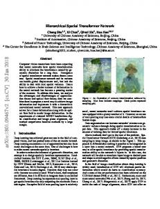
4. Proposed Robust m-Child Family Tree Based Structured Hierarchical Overlay Network Architecture In a structured overlay system, finding an efficient and scalable solution for content discovery in the presence of massive churn is a challenging problem. In this section, we present a robust and fault-tolerant structured hierarchical overlay structure to counter churn attack. The basic mechanism behind our approach is to give a noncritical role to newly joined nodes so that their failure will have no or short range effect. Figure 1 represents the structure of the proposed overlay network. The proposed architecture is built on a two-tier hierarchical architecture, where the higher tier consists of super peer nodes representing ring nodes and forming the root of the family tree and lower tier represent the remaining family tree. The key idea behind using family tree structure is to create a scalable and robust overlay network, where each node
can store at the max 𝑁 files. Every family tree has a super peer as its root node. Local peers in the same family tree are connected to other family trees through their root node and are arranged. In case of a query message, the local node will calculate the given key using uniform mapping rule. If a key lies in its own jurisdiction, it will find the node responsible; otherwise query will be moved upward until it finds the node responsible or it reaches the root node. At the root node, it will check whether required key lies in the local m-child family tree or not. If it lies there, then request will be sent to local m-child family subtree; otherwise root will find the super peer responsible for holding the key and forward the query to appropriate super peer in the ring topology. Definition 1. Each regular peer 𝑝 will be a member of local m-child family tree with root node 𝑆𝑛 (member of the layer 1 chord ring), if 𝑆𝑛 is the first node whose ID is followed by the ID of the peer 𝑝. To provide a better understanding of the proposed hierarchical model, we first provide an overview of working of
6
Journal of Computer Networks and Communications Node id = 400
1
2 · · · 99
C1
2
C1
100
C3
C2
C2
101 · · · 199
C4
C3
201 · · · 299
200
C1
301
99
C4
301 · · · 399
300
400
C3
C2
C4
399
Node id = 211 201
C3
C2
C1
C4
299
Node id = 121 C1
101
C2
126
C3
150
C4
174
199 Node id = 185
Node id = 111 102
C1
C2
C3
C4
125
175
C1
C2
Node id = 132 127
C1
C2
C3
C4
C3
C4
198
Node id = 166 149
151
C1
C2
C3
C4 173
Figure 2: Anatomy of robust m-child family tree.
robust m-child family tree and how overlay peers will be organized into robust m-child family tree topology. 4.1. Basic m-Child Family Tree. We consider trees that store a finite set 𝐾 of keys in the range (𝐾𝑖 , 𝐾𝑖+1 , . . . , 𝐾𝑛 ), where 𝐾𝑖 is the node ID of the root node (super peer) and 𝐾𝑛+1 is the node ID of immediate successor of the root node in the top layer chord ring as shown in Figure 2. Each node 𝑁 of the tree contains a sequence of keys 𝐾𝑖 split into four equal ranges separated by pointers 𝑐[𝑥] referring to its child node. For the leaf nodes all the child pointers are null. Initially, all the keys are stored by the root node. As a new node joins the tree, it will be added as a leaf node of a subtree based on its node ID value. The child pointer of the parent node will be updated accordingly and the parent will delegate the key storage responsibility of appropriate range (the range in which joining node’s ID is falling) to its child node. The values of keys of separate ranges are stored in each subtree. 4.2. Anatomy of Robust m-Child Family Tree. The creation and maintenance of family tree structure is quite simple. This tree structure fulfils the property that insertions are restricted to be as leaf nodes. So, new nodes can join or leave the data structure without causing much inconsistency and make this system suitable for dynamic environments by decreasing the cost of insertion and deletion. In the proposed architecture, family tree with the fixed root and additional robust pointer structure and robust representation of stored keys is used. An m-child family tree is the one in which a tree can have 𝑚 children.
Definition 2 (proposed m-child family tree). This is a self-modifying, multiway structure of order 𝑚, where each node 𝑁 is defined as a tuple of [(Range1 , 𝐶1 ), (Range2 , 𝐶2 ), (Range3 , 𝐶3 ), . . . , (Range𝑚 , 𝐶𝑚 ), bool, 𝑈[𝑥], 𝑝], where Range𝑖 is the set of key values stored by the specific subtree in the ascending order (1 ≤ 𝑖 ≤ 𝑚), 𝐶𝑖 is the pointer from node 𝑁 to its child (1 ≤ 𝑖 ≤ 𝑚), bool is a Boolean variable, which will be true if 𝑁 is a leaf node and false otherwise, and 𝑝 and 𝑈[𝑥] are the pointers from the node 𝑡 to its parent and uncle (parent’s sibling), respectively. The values of keys separate the ranges stored in each subtree. The robust pointer structure and new insertion as leaf node make this structure suitable for implementation of overlay network in which new nodes are usually unreliable. In robust m-child family tree structure nodes promptly react to node failure to maintain connectivity. The structured hierarchical overlay network implements the network as a combination of chord and robust m-child family tree. The information sharing between different peers will be implemented using this combination, where chord network will identify the m-child family tree responsible for storage of a particular range of data and this m-child family tree will then find the particular node responsible for it. This m-child family tree is the basic data structure for a structured hierarchical overlay network with a hash table distributed on it. There is a node in an m-child family tree for each peer in the system. An m-child family tree has spread its nodes over different peers and these values are mapped to hash of an IP address of these peers.
Journal of Computer Networks and Communications
5. Proposed Structured Hierarchical Overlay Network Algorithms In this section, we introduce different algorithms for creating, maintaining, and querying an m-child family tree based hierarchical structured overlay network that derives its characteristics from the working of general real time family tree structure. Our goal is to create an m-child family tree rooted on super node to store a range of values on different nodes in an effective, fault-tolerant, and efficient manner. In this architecture, top level chord architecture is formed by most reliable (high expected life time) nodes and reduces the expected number of hops and failures. 5.1. Super Peer Selection. In order to create the hierarchical overlay, first, we need to select top layer overlay nodes. More stable nodes will be selected as super peers to minimize the churn effects in the top layer overlay. Various researchers [33– 35, 56] have proposed different techniques to select stable peers and designate them as super peers of hierarchical overlays. In our architecture, we have used a gradient search algorithm [35] to discover highly stable peers for the top layer chord overlay network. In this algorithm peer’s uptime is used as a metric to compute the stability of the peer to check whether the node is the suitable candidate to take the responsibility of a super peer. Each super peer node will maintain two tables: finger table for top layer chord overlay and routing table for local m-child family tree. The routing table at each node of m-child family tree will store entries for its immediate descendants and its parent and uncles (siblings of the parent node). 5.2. Tree Creation. The initialization of m-child family tree involves the steps mentioned in algorithm explained in Algorithm 1. In our algorithm; we first designate the top layer chord overlay node (super peer) as the root node of the m-child family tree. As we know, every chord node with ID m is responsible for the storage of a range of keys between 𝑚 and 𝑀, where 𝑀 + 1 is the ID of its immediate successor in the chord overlay. So, we divide this range into separate chunks, so that layer 2 overlay nodes that have to join the overlay network will choose their subtree according to their ID in the appropriate chunk. As already specified in Section 4, every m-child family tree node is a tuple of [(Range1 , 𝐶1 ), (Range2 , 𝐶2 ), (Range3 , 𝐶3 ), . . . , (Range𝑚 , 𝐶𝑚 ), bool, 𝑈[𝑥], 𝑝], so we have to set the pointers for the child, parent, and uncle nodes of the root nodes. Initially they all are NULL pointers and their corresponding entry will be made in the neighbourhood table of the node. These pointers and neighbourhood table will be updated as the new nodes will join the overlay network. 5.3. Peer Join. In order to join an overlay, a requesting node must know at least one peer, who is already registered in the overlay network. That registered peer can be a super peer or
7
Create Tree(T) { (1) 𝑥 = allocate node() (2) Parent = NULL (3) 𝑥[𝑛] = Range(𝑚, 𝑀) (4) Set Root(𝑇) = 𝑥 (5) Divide in chunk(𝑥[𝑛], 𝑡, ch[𝑝]) (6) Repeat for 𝑖 = 1 to 𝑡 (7) 𝑐[𝑖] = Null (8) Uncle[𝑖] = Null (9) End for (10) Return } Divide in chunk(x[n], t, ch[p]) { (1) ch.size = roundoff(𝑛/𝑡) (2) Repeat for 𝑖 = 1 to 𝑡 (3) size = 𝑚 + ch.size (4) ch[𝑖] = Range(𝑚 ⋅ ⋅ ⋅ size) (5) 𝑚 = size (6) end for } Algorithm 1: M-child family tree creation.
a lower tier peer. The steps of joining process are explained with the help of an algorithm in Algorithms 2 and 3. 5.3.1. Impact of Node Join. The impact of joining of a node on the performance of the proposed architecture is negligible. Because, regardless of the ID of joining node, it will always be inserted as a leaf node and its parent will delegate its load to this newly joined node and set its pointer accordingly. So, all the routing table entries will be correct and thus queries can be routed to appropriate nodes without disruption. Theorem 3. In a proposed network of 𝑁 nodes, the expected number of hops for a join operation is 𝑂(log 𝑛), where n is the total number of nodes in the overlay and (𝑂(1) + 𝑂(𝑚(𝑚 − 1))) neighbourhood tables get updated after this join operation, where m is the degree of m-child family tree. 5.4. Maintenance of Failure of Peers and Super Peers. Maintenance of the proposed approach is mainly of two types: intratree and intertree maintenance. Intratree maintenance handles the impact of normal (informed leave) or abnormal failure on the structure of B-tree. Intertree maintenance aims to preserve super peer’s chord structure in the event of super peer failure or informed leave. 5.4.1. Intertree Maintenance (Top Layer Maintenance). In order to withstand churn attack, top layer overlay architecture is made up of highly stable super peer. In order to provide reliability, each super peer is associated with a backup node. In case of informed leave, super peer will inform the backup node about its status and delegate the responsibility. Whereas, in order to handle failure of super peer, a background periodic stabilization process is used. In this stabilization process,
8
Journal of Computer Networks and Communications
Join (n1 , n2 ) { // node 𝑛1 wants to join the overlay network and knows a node 𝑛2 that is currently a member of overlay network. (1) If 𝑛2 is a super node(top layer node), then (2) If host tree is responsible for 𝑛1 , then (3) Go to step (6). (4) Else (5) 𝑇 = Find Tree(𝑛1 ) // joining node perform a tree lookup, which is routed in the top level overlay to the super node responsible for the key. (6) 𝑛1 .Join Tree(𝑇) (7) else // if 𝑛2 is not a super node (8) 𝑛2 .Forward Request(root) // node 𝑛2 will forward the 𝑛1 ’s join request to its root (9) if root node(host tree) is the super node responsible for the key, then (10) 𝑛1 .Join Tree(𝑇) (11) else //if root node(host tree) is not responsible for the key (12) 𝑇 = Find Tree(𝑛1 ) (13) 𝑛1 .Join Tree(𝑇) (14) Return. } n2 .Find Tree (n1 ) { // node 𝑛2 will find the super node responsible for node 𝑛1 (1) 𝑇 = (𝑛2 , successor) (2) if 𝑛1 ∈ 𝑇 // super node responsible for the key is found (3) return 𝑇 (4) else // forward the query to next node of the ring (5) 𝑇.Find Tree (𝑛1 ) } n2 .Forward Request (n1 , Root) { // Forward the join request from node 𝑛2 to the root of the tree (1) If (𝑛2 is not a root node), then (2) 𝑛2 = parent(𝑛2 ) (3) 𝑛2 .Forward Request(𝑘1 , Root) (4) else (5) Root = 𝑛2 (6) return } Algorithm 2: Peer join operation in proposed architecture.
backup node will ping the corresponding node after regular interval and take its responsibility in case of failure detection. 5.4.2. Intratree Maintenance (Tier 2 Maintenance). Intratree maintenance mechanism is responsible for maintaining the structure of robust m-child family tree in case of node failure or informed leave. In a general tree structure with the loss of the parent node the descendants will be disconnected from the tree. But, in case of an m-child family tree structure after parent loss, they will connect to their grandparents through their uncle (each node will store its parent’s address) and grandparent will delegate the parent’s responsibility to the appropriate grandchild. In case of failure of nodes, the periodic stabilization mechanism will detect the node failure and take the following corrective measures: (1) Every child will perform a periodic check to find whether its parent is alive or not. So, child node will identify the node failure.
(2) After failure identification, the child will contact its uncle to inform the grandparent about the failure of their parent node 𝑥. (3) After receiving intimation about failure, a grandparent will apply the informed leave mechanism to arrange the graceful leave of its failed child. The informed leave mechanism is explained as shown in Algorithm 4. 5.4.3. Impact of Node Failure. The impact of failure of nodes lying on m-child family tree is very little in the local subtree only. When a lower tier node fails either its parent or child nodes will trigger a recovery mechanism similar to informed leave mechanism to restore their network connectivity with the rest of the overlay. Each node will also maintain pointers to their uncles, so that in case of cascade failures in a single subtree they can restore the connectivity by contacting their common alive parent with other subtrees (rooted at the same super peer) by contacting their uncle. The additional sets
Journal of Computer Networks and Communications
9
n1 .Join Tree (T) { Input: Tree 𝑇 has a root 𝑅(Super peer), : 𝑅 is responsible for a range of keys (𝑚 to 𝑀), where 𝑚 is the minimum key value and 𝑀 is the maximum key value : Range is divided into 4 almost equal chunks: (ch[1], ch[2], ch[3] and ch[4]) (1) Repeat for 𝑖 = 1 to 4 (2) If 𝑛1 ∈ ch[𝑖], then (3) If 𝑐[𝑖] == NuLL, then (4) Set 𝑐[𝑖] = 𝑛1 (5) Delegate ch[𝑖] values to node 𝑛1 . (6) parent = 𝑇 (7) 𝐿 = parent(𝑇) // 𝐿 is the grandparent of newly joined node (8) Initialize fingers (𝑛1 , 𝐿) // initialize all the child, parent and uncle’s pointer values (9) break (10) Else (11) Set 𝑇 = 𝑐[𝑖] (12) break. (13) End For. (14) 𝑛1 .Join Tree(𝑇) (15) Return } Initialize fingers (n1 , L) { (1) Divide in chunk(𝑥[𝑛], 4, ch[4]) (2) Repeat for 𝑖 = 1 to 4 (3) 𝑐[𝑖] = Null (4) 𝑈[𝑖] = 𝐿(𝑐[𝑖]) (5) End for } Algorithm 3: Peer join operation in the responsible tree of the proposed architecture.
Leave(n1 ) { // node 𝑛1 wants to leave the overlay network. (1) If 𝑛1 is a leaf node, then (2) 𝑛1 delegates its range to its parent and inform its leaving to all neighbours. (3) Else // 𝑛1 is not a leaf node (4) PR = Predecessor(𝑛1 ) // predecessor of the node in its local subtree (5) PTR = Parent(PR) (6) PT = Parent(𝑛1 ) (7) PR delegates its load to PTR (8) 𝑁1 delegates its load to PR. (9) PT now points to PR and node 𝑛1 can leave now. (10) Return } Algorithm 4: Peer leave mechanism of proposed architecture.
of links maintained in neighbourhood table apart from the standard links of overlay aid robustness of the proposed architecture. Theorem 4. The maintenance operation for failed node 𝑛1 will affect 𝑂(log 𝑡) nodes with (𝑂(2) + 2𝑂(𝑚(𝑚 − 1))) neighbourhood tables updates, where 𝑡 is the number of nodes in a subtree rooted on parent of failed node and m is the degree of m-child family tree.
5.5. Lookup Algorithm. Any node from top tier or lower tier can issue a lookup request. In the second case, query should first be forwarded to the connected super peer in order to process it. Super peer will find the tree responsible for answering it, by routing the lookup request in the top tier chord overlay. After successfully finding the tree responsible, the root node will search for the node actually responsible for storing the key as shown in Algorithms 5 and 6.
10
Journal of Computer Networks and Communications
Key Lookup (n1 , k1 ) { // lookup algorithm for key 𝑘1 issued by node 𝑛1 (1) If 𝑛1 is a super node of tree 𝑇, then (2) If (𝑛1 can answer query) then // if issued query lies in local tree (3) Node = 𝑘1 .Search Tree(𝑇) (4) Else // if 𝑛1 cannot answer the query (5) 𝑇 = 𝑛1 .Find Tree(𝑘1 ) // query is routed in the top layer overlay to find the super node responsible for the key (6) Node = 𝑘1 .Search Tree(𝑇) // find the node responsible for the storage of key 𝑘1 in tree 𝑇 (7) Else // 𝑛1 is not a super node (8) If (𝑛1 can answer query) then // if issued query lies in local sub tree range (9) 𝑇 = 𝑛1 (10) Node = 𝑘1 .Search Tree(𝑇) (11) Else // if query is not in local subtree (12) 𝑛1 .Forward Request(𝑘1 , root) // node 𝑛1 will forward the key lookup request to its root (13) Go to step (2). (14) Return } n1 .Find Tree (k1 ) { // node 𝑛1 will find the super node responsible for node 𝑘1 (1) 𝑇 = (𝑘1 , successor) (2) if (𝑘1 ∈ 𝑇) // super node responsible for the key is found (3) return 𝑇 (4) else // forward the query to next node of the ring (5) 𝑇.Find Tree (𝑘1 ) } n1 .Forward Request (k1 , Root) { // Forward the request from node 𝑛1 to the root of the tree (1) If (𝑛1 is not a root node), then (2) 𝑛1 = parent(𝑛1 ) (3) 𝑛1 .Forward Request(𝑘1 , Root) (4) else (5) Root = 𝑛1 Return } Algorithm 5: Key lookup operation in proposed architecture.
k1 .Search Tree (T) { //After finding the responsible tree, query will be forwarded towards the appropriate child of tree (1) If 𝑘1 lies on the root node, then (2) Return 𝑘1 (3) Else // if key lies on one of its child (4) Repeat for 𝑖 = 1 to 4 (5) if (𝑘1 ∈ ch[𝑖]), then (6) 𝑇 = 𝑐[𝑖] (7) Break (8) End for (9) 𝑘1 .Search Tree(𝑇) (10) Return. } Algorithm 6: Key lookup operation in the responsible tree of the proposed architecture.
Journal of Computer Networks and Communications
11
Table 2: Simulation parameters. Type
Simulation parameters
Parameters
Values
Network Size
Max 10000 Multiple churn generators (no churn initially, Pareto churn for normal failure, and lifetime churn for intentional attack) For lifetime churn 1600 s 1300 s 1000 s 700 s (churn attack) For Pareto churn 2,000 s
Churn generator Mean node lifetime
Common architecture parameters
Fix finger delay Stabilization delay Successor list size
120 s 60 s 4
Node distribution
Percentage of super peers Percentage of regular peers Percentage of malicious peers in regular peers for churn attack scenario only
5 95
Degree of m-child family tree
For basic proposed architecture
10
20
2
Theorem 5. In a proposed network of 𝑁 nodes, the search for key 𝑘1 is carried out in 𝑂(log 𝑁) steps.
6. Experiments and Results To prove and verify the proposed hierarchical structure, the omnet++ based overlay simulation framework OverSim [57] is used. The OverSim is an event based simulator with a layered architecture to provide a common API for application development. Its simulation framework is suitable for the design, evaluation, and comparison of different overlay network models at a large scale with support of different underlay networks. The new overlay modules are declared using NED language and their behaviour is customized using C++. The OverSim architecture provides a variety of underlay networks varying from simple underlay to more real IPV4 underlay. 6.1. Experimental Settings. The main parameters of our simulation are listed in Table 2. The simulations are performed using and updating the existing chord architecture in the OverSim simulator. All simulations are conducted on a network of varying size from 500 to 10000 nodes; each node assigned random 160-bit node ID. The network size defines the total number of overlay nodes in the simulation. In our proposed architecture, we have three types of nodes: super peer nodes (stable nodes in chord ring), regular peers (legitimate peers in tree topology), and malicious nodes (nodes with a short life span). As most of the existing analytical and numerical results indicate the presence of a small number of stable nodes in an overlay network, thus, in our proposed architecture, layer 1 overlay comprises about 5% of the total overlay population [58] and the remaining 95% of population comprises a mix of regular and malicious peers for different churn attack scenarios as specified in Table 2. The selection of churn generator is mainly based on the type of churn behaviour simulation. For legitimate churn
30
4
40
400 s
50
6
behaviour, a Pareto churn model is used, which will generate heavy tailed session times similar to real results from many real time peer to peer systems. But, if an attacker wants to insert many short lived peers in the overlay network, then the lifetime churn generator is the most appropriate churn attack generator as it is based on the Weibull distribution, which is known to be best for modelling a variety of life behaviour. The level of churn is simulated by varying the values of mean node lifetime between 400 seconds and 1,600 seconds. A shorter lifetime means a higher level of churn [16]. The stabilization delay and the fix finger delay refer to the duration between periodic ping to make sure that the neighbour and the exponential neighbours (finger table entries) are alive and successor table and finger table pointers are up to date. Each node on the chord ring maintains a successor list of size 4. The value of these parameters is chosen based on the most recent studies for the performance of chord based overlay networks. The degree of m-child family tree describes the maximum number of children for a node. The fixed value of degree of proposed m-child family tree based overlay architecture used in the experimental settings is emphasized in bold typeface. 6.2. Simulation Results. Two things are evaluated here: first proving that the hierarchy introduced in the proposed architecture added value in terms of performance and scalability; second, proving the robustness of the proposed architecture to the intentional churn attack. 6.2.1. Performance of Proposed Hierarchical Architecture. To evaluate the performance of proposed hierarchical overlay architecture, we simulate it with nodes having legitimate churn behaviour. The following parameters are used for performance assessment of the proposed structure.
12
Journal of Computer Networks and Communications 10 10
Average lookup hop
Average lookup hop
8 8
6
4
4
2
6
0
2000
4000
6000
8000
2
10000
Number of nodes
0
Average message delivery hop with proposed architecture Average message delivery hop chord Average message delivery hop BATON Average message delivery hop m-way tree
Figure 3: Comparison of different overlay network architectures with varying population.
2000
6000 4000 Number of nodes
8000
10000
Average message delivery hop with 6-child family tree Average message delivery hop with 4-child family tree Average message delivery hop with 2-child family tree
Figure 4: Average lookup hop count with different degree of family tree. 200
(i) Average Lookup Hop Count. The average search hop count measures the performance of a system as the number of average hops needed for search. Figure 3 represents the performance of different overlay networks with respect to different overlay network sizes. The results clearly show that the proposed hierarchical architecture has better results as compared to other architectures due to stable super peer based top layer and the divide and conquer principle for message forwarding in the appropriate subtree with the use of tree based architecture in layer 2. From Figure 3, it is clear that the tree based architectures with fault tolerance capability (redundant pointers) such as BATON [19] perform better than chord architecture [24] due to underlying divide and conquer approach, but lack of redundancy in multiway trees [59] will make the situation worse by failure of the whole subtree in case of the parent failure. We also measure the average hop count by varying the degree of m-child family tree with 𝑚 = 2, 4, 6, respectively, with respect to same set of participants as shown in Figure 4. From Figure 4, it is evident that the lookup hop count is reduced by increasing the degree of m-child family tree. Because, by increasing the degree of m-child family tree, the height of the tree will be reduced and ultimately it will decrease the number of hops to search a particular key. Thus, these results verify our first claim that our proposed architecture is efficient as compared to existing architectures in terms of minimum lookup delay. However, with the increase in the degree of m-child family tree, the number of pointers to be maintained at each node will also increase. Thus, designers have to select the degree of m-child family tree by taking this additional overhead in consideration.
Routing table update messages
180 160 140 120 100 80 60 40 20 0
0
2000
4000
6000
8000
10000
Number of nodes Stabilization messages for join in proposed architecture Stabilization messages for join in m-way tree Stabilization messages for join in BATON Stabilization messages for join in chord Stabilization messages for leave in proposed architecture
Figure 5: Average stabilization messages for single node join/leave.
(ii) Stabilization Messages for Single Node Join and Failure. The purpose of this set of experiments is to measure the overhead caused by the open and dynamic behaviour of overlay network nodes. Figure 5 presents the average number of stabilization messages required for a single join and leave operation. Our experiment confirms that the overhead associated with join operations in proposed architecture is quite low as compared to other systems as a new node always
Journal of Computer Networks and Communications
13
100 3000 2500
90 85 80 75 70 0.1
0.2
0.3
0.4
0.5
Churn rate Success ratio_chord Success ratio_proposed architecture
Figure 6: Lookup success ratio with varying levels of churn attack.
has to join as a leaf node and needs to update the pointer of its parent node and uncles (sibling of the parent node), whereas, in case of BATON [19] and multiway tree [59], a new node can join at any position based on its node ID and has to update a large number of pointers to their parent node, siblings, child nodes, and so forth. The join operation of BATON [19] architecture is more costly as compared to multiway tree [59] due to its need to store a large number of redundant pointers for fault tolerance. Moreover, as compared to other architectures, the proposed architecture partitions the overlay into multiple suboverlays and in turn reduces the number of routing table updates per node in case of join and failure. 6.2.2. Robustness of Proposed Hierarchical Architecture. In order to evaluate the effect of the intentional churn attack, we performed simulations starting with a number of honest peers only. We implemented a simple churn attack, where a significant number of nodes are added and removed from the network in each round. In our simulation model first intentional churn attack begins after the super peer topology has been constructed and has stabilized with the tree nodes. The performance of our proposed architecture is expected to remain consistent under intentional churn attack where a significant number of nodes are added and removed from the system within short time duration. We also evaluate the robustness of the proposed architecture under varying levels (represents the percentage of nodes that join/leave the system at each round) of churn attack. (i) Lookup Success Ratio under Churn Attack. In this set of experiments, we measure the ability of proposed approach to achieve robust lookup operations despite the presence of heavy intentional churn attack. The robust lookup is realized by forcing the unreliable new nodes to get inserted at leaf levels. Figure 6 clearly represents the robust behaviour of proposed architecture: for 25% churn, lookup success ratio is almost 98% and for 50% churn 88% of the queries are correctly answered. These results clearly indicate the robustness of the proposed architecture under intentional churn attack as our
Number of disconnections
Lookup success ratio
95
2000 1500 1000 500 0
0
0.1
0.2
0.3
0.4
0.5
Churn rate Number of disconnections for chord Number of disconnections for proposed architecture
Figure 7: Effects of varying levels of churn on overlay network structure.
architecture can provide lookup performance guarantees even when 50% of nodes are malicious. (ii) Number of Disconnections under Churn Attack. It is the number of peers that lose their connections to the rest of the overlay due to churn attack. The experimental results show that the proposed architecture remains well connected under churn attack. Figure 7 shows that the proposed architecture reduces the large number of disconnections as compared to chord [24] overlay network under varying levels of churn attack. The number of disconnections will be reduced due to the isolation of the churn property of hierarchical network; along with this, our attack model usually triggers the malicious users to join the overlay network in rounds and all these malicious users will join as leaf nodes of the suboverlay. Thus, it will not impact the working of legitimate nodes and results in less number of disconnections.
7. Conclusion The overlay networks emerge as a popular platform for the construction of large scale distributed systems; however the attackers can unleash the various attacks against overlay networks by exploiting their open nature. We presented a robust hierarchical overlay network to counter the intentional churn attack by adding the newly joined nodes at the leaf levels only with limited connectivity. The proposed architecture offers more stability, lookup efficiency, and less maintenance overhead by using more reliable peers at the top layer chord ring and regular peers inside m-child family tree at layer 2. The m-child family tree architecture reduces the lookup and maintenance message overhead by using divide and conquer principle for message forwarding in the appropriate subtree. But, this efficiency comes at a cost of retaining redundant
14 uncle pointers at each node and incorporation of some sort of centrality in the distributed overlay architecture. Our simulation results demonstrate the effectiveness of the proposed hierarchical architecture to counter different churn attack levels without affecting the performance and connectivity of live peers with minimum maintenance message overhead.
Journal of Computer Networks and Communications
[14]
[15]
Competing Interests The authors declare that they have no competing interests.
[16]
References [1] J. Buford, H. Yu, and E. K. Lua, P2P Networking and Applications, USA Morgan Kuafmann, 2009. [2] M. Srivatsa and L. Liu, “Vulnerabilities and security threats in structured overlay networks: a quantitative analysis,” in Proceedings of the 20th Annual Computer Security Applications Conference (ACSAC ’04), pp. 252–261, December 2004. [3] L. Ganesh and B. Y. Zhao, “Identity theft protection in structured overlays,” in Proceedings of the 1st International Conference on Secure Network Protocols (NPSEC ’05), pp. 49–54, IEEE, Washington, DC, USA, 2005. [4] R. Kaur, A. L. Sangal, and K. Kumar, “Secure Overlay Services (SOS): a critical analysis,” in Proceedings of the 2nd IEEE International Conference on Parallel, Distributed and Grid Computing (PDGC ’12), pp. 457–462, December 2012. [5] E. K. Lua, J. Crowcroft, M. Pias, R. Sharma, and S. Lim, “A survey and comparison of peer-to-peer overlay network schemes,” IEEE Communications Surveys and Tutorials, vol. 7, no. 2, pp. 72–93, 2005. [6] E. Sit and R. Morris, “Security considerations for peer-to-peer distributed hash tables,” in Proceedings of the 1st International Workshop on Peer-to-Peer Systems (IPTPS ’01), pp. 261–226, London, UK, 2002. [7] D. S. Wallach, “A survey of peer-to-peer security issues,” in Proceedings of the International Conference on Software Security: Theories and Systems, pp. 42–57, Berlin, Germany, 2002. [8] B. Pretre, Attacks on peer-to-peer networks [Ph.D. thesis], Department of Computer Science Swiss Federal Institute of Technology (ETH), Z¨urich, Switzerland, 2005. [9] A. Singh, T.-W. Johnny Ngan, P. Druschel, and D. S. Wallach, “Eclipse attacks on overlay networks: threats and defenses,” in Proceedings of the 25th IEEE International Conference on Computer Communications (INFOCOM ’06), Barcelona, Spain, April 2006. [10] A. Singh, M. Castro, P. Druschel, and A. Rowstron, “Defending against eclipse attacks on overlay networks,” in Proceedings of the 11th Workshop on ACM SIGOPS European Workshop (EW ’11), Leuven, Belgium, September 2004. [11] D. Germanus, S. Roos, T. Strufe, and N. Suri, “Mitigating eclipse attacks in peer-to-peer networks,” in Proceedings of the IEEE Conference on Communications and Network Security (CNS ’14), pp. 400–408, San Francisco, Calif, USA, October 2014. [12] F. D. L´opez-Fuentes, I. Eugui-De-Alba, and O. M. Ort´ız-Ruiz, “Evaluating P2P networks against eclipse attacks,” in Proceedings of the Iberoamerican Conference on Electronics Engineering and Computer Science, vol. 3, pp. 61–68, Guadalajara, Mexico, May 2012. [13] Z. Trifa and M. Khemakhem, “Mitigation of sybil attacks in structured P2P overlay networks,” in Proceedings of the 8th
[17]
[18]
[19]
[20]
[21]
[22] [23]
[24]
[25]
[26]
[27]
[28]
[29]
International Conference on Semantics, Knowledge and Grids (SKG ’12), pp. 245–248, Beijing, China, 2012. K. Aberer, A. Datta, and M. Hauswirth, “Efficient, selfcontained handling of identity in peer-to-peer systems,” IEEE Transactions on Knowledge and Data Engineering, vol. 16, no. 7, pp. 858–869, 2004. H. Rowaihy, W. Enck, P. McDaniel, and T. La Porta, “Limiting sybil attacks in structured P2P networks,” in Proceedings of the 26th IEEE International Conference on Computer Communications (INFOCOM ’07), pp. 2596–2600, May 2007. R. Kaur, A. L. Sangal, and K. Kumar, “Analysis of different churn models in chord based overlay networks,” in Proceedings of the Recent Advances in Engineering and Computational Sciences (RAECS ’14), pp. 1–6, March 2014. Y.-K. Kwok, “Autonomic peer-to-peer systems: incentive and security issues,” in Autonomic Computing and Networking, pp. 205–236, Springer, New York, NY, USA, 2009. B. Awerbuch and C. Scheideler, “Towards a scalable and robust DHT,” Theory of Computing Systems, vol. 45, no. 2, pp. 244–260, 2009. H. V. Jagadish, B. C. Ooi, and Q. H. Vu, “BATON: a balanced tree structure for peer-to-peer networks,” in Proceedings of the 31st International Conference on Very Large Data Bases (VLDB ’05), pp. 661–672, September 2005. A. Rowstron and P. Druschel, “Pastry: scalable, decentralized object location and routing for large-scale peer-to-peer systems,” in Proceedings of the 18th IFIP/ACM International Conference on Distributed Systems Platforms (Middleware ’01), Heidelberg, Germany, 2001. K. Hildrum, J. D. Kubiatowicz, S. Rao, and B. Y. Zhao, “Distributed object location in a dynamic network,” in Proceedings of the 14th Annual ACM Symposium on Parallel Algorithms and Architectures, pp. 41–52, Winnipeg, Canada, August 2002. C. Rhea, Open DHT: a public DHT service [Ph.D. thesis], University of California, Berkeley, Calif, USA, 2005. M. Castro, M. Costa, and A. Rowstron, “Performance and dependability of structured peer-to-peer overlays,” in Proceedings of the International Conference on Dependable Systems and Networks, pp. 9–18, July 2004. I. Stoica, R. Morris, D. Liben-Nowell et al., “Chord: a scalable peer-to-peer lookup protocol for Internet applications,” IEEE/ACM Transactions on Networking, vol. 11, no. 1, pp. 17–32, 2003. S. Rhea, D. Geels, T. Roscoe, and J. Kubiatowicz, “Handling churn in a DHT,” in Proceedings of the USENIX Annual Technical Conference, Boston, Mass, USA, June 2004. D. Stutzbach and R. Rejaie, “Understanding churn in peerto-peer networks,” in Proceedings of the 6th ACM SIGCOMM on Internet Measurement Conference (IMC ’06), pp. 189–202, October 2006. F. Kuhn, S. Schmid, and R. Wattenhofer, “Towards worst-case churn resistant peer-to-peer systems,” Distributed Computing, vol. 22, no. 4, pp. 249–267, 2010. Z. Liu, R. Yuan, Z. Li, H. Li, and G. Chen, “Survive under high churn in structured P2P systems: evaluation and strategy,” in Proceedings of the 6th International Conference on Computational Science, pp. 404–411, Reading, UK, May 2006. F. Kuhn, S. Schmid, and R. Wattenhofe, “A self-repairing peerto-peer system resilient to dynamic adversarial churn,” in Proceedings of the 4th International Conference on Peer-to-Peer Systems, pp. 13–23, Berlin, Germany, 2005.
Journal of Computer Networks and Communications [30] J. Liang, R. Kumar, and K. W. Ross, “The kazaa overlay: a measurement study,” Computer Networks Journal, Elsevier, vol. 49, no. 6, 2005. [31] B. Yang and H. Garcia-Molina, “Designing a super-peer network,” Tech. Rep., Stanford University, Stanford, Calif, USA, 2002, http://infolab.stanford.edu/∼byang/pubs/superpeer.pdf. [32] S.-J. Zhou, Study on the distributed routing algorithm and its security for Peer-to-Peer computing [Ph.D. thesis], University of Electronic Science and Technology of China, Chengdu, China, 2004. [33] L. Garces-Erice, E. Biersack, P. Felber, K. Ross, and G. Urvoy Keller, “Hierarchical peer-to-peer systems,” in Euro-Par 2003 Parallel Processing: 9th International Euro-Par Conference Klagenfurt, Austria, August 26–29, 2003 Proceedings, vol. 2790 of Lecture Notes in Computer Science, pp. 1230–1239, Springer, Berlin, Germany, 2003. [34] W. Nejdl, M. Wolpers, W. Siberski et al., “Super-peer-based routing and clustering strategies for RDF-based peer-to-peer networks,” in Proceedings of the 12th International Conference on World Wide Web (WWW ’03), pp. 536–543, Budapest, Hungary, May 2003. [35] J. Sacha, J. Dowling, R. Cunningham, and R. Meier, “Discovery of stable peers in a self organizing peer-to-peer gradient topology,” in Proceedings of the 6th IFIP WG 6.1 International Conference on Distributed Applications and Interoperable Systems (DAIS ’06), pp. 70–83, Athens, Greece, June 2006. [36] F. Buccafurri and G. Lax, “TLS: a tree-based DHT lookup service for highly dynamic networks,” in Proceedings of the OTM Confederated International Conferences, CoopIS, DOA, and ODBASE, Agia Napa, Cyprus, October 2004. [37] S. Z¨ols, Q. Hofst¨atter, Z. Despotovic, and W. Kellerer, “Achieving and maintaining cost-optimal operation of a hierarchical DHT system,” in Proceedings of the IEEE International Conference on Communications (ICC ’09), pp. 1–6, June 2009. [38] R. Kaur, A. L. Sangal, and K. Kumar, “Modelling and simulation of adaptive neuro-fuzzy based intelligent system for predictive stabilization in structured overlay networks,” Engineering Science and Technology, an International Journal, 2016. [39] P. Linga, I. Gupta, and K. Birman, “A churn-resistant peer-topeer web caching system,” in Proceedings of the 2nd International Workshop on Peer-to-Peer Systems (IPTPS ’04), February 2004. [40] M. Castro, M. Costa, and A. Rowstron, “Performance and dependability of structured peer to-peer overlays,” Tech. Rep., Microsoft Research, 2003. [41] K. Hildrum, J. D. Kubiatowicz, S. Rao, and B. Y. Zhao, “Distributed object location in a dynamic network,” in Proceedings of the 14th Annual ACM Symposium on Parallel Algorithms and Architectures (SPAA ’02), pp. 41–52, August 2002. [42] S. Rhea, D. Geels, T. Roscoe, and J. Kubiatowicz, “Handling churn in a dht,” Tech. Rep. ucb/csd-3-1299, UC Berkeley, Computer Science Division, Berkeley, Calif, USA, 2003. [43] J. Saia, A. Fiat, S. Gribble, A. R. Karlin, and S. Saroiu, “Dynamically fault-tolerant content addressable networks,” in Proceedings of the 1st International Workshop on Peer-to-Peer Systems (IPTPS ’02), Cambridge, Mass, USA, March 2002. [44] P. Brighten Godfrey, S. Shenker, and I. Stoica, “Minimizing churn in distributed systems,” in Proceedings of the Conference on Applications, Technologies, Architectures, and Protocols for Computer Communications, pp. 147–158, 2006.
15 [45] F. E. Bustamante and Y. Qiao, “Designing less-structured P2P systems for the expected high churn,” IEEE/ACM Transactions on Networking, vol. 16, no. 3, pp. 617–627, 2008. [46] X. Meng, X. Chen, and Y. Ding, “Using the complementary nature of node joining and leaving to handle churn problem in P2P networks,” Computers and Electrical Engineering, vol. 39, no. 2, pp. 326–337, 2013. [47] B. Y. Zhao, J. Kubiatowicz, and A. D. Joseph, “Tapestry: an infrastructure for Fault-tolerant wide-area location and routing,” Tech. Rep. UCB/CSD-01-1141, Computer Science Division, UC Berkeley, Berkeley, Calif, USA, 2001. [48] X. Li, J. Misra, and C. G. Plaxton, “Active and concurrent topology maintenance,” in Proceedings of the 18th International Conference on Distributed Computing (DISC ’04), pp. 320–334, Amsterdam, Netherlands, 2004. [49] M. El Dick, E. Pacitti, R. Akbarinia, and B. Kemme, “Building a peer-to-peer content distribution network with high performance, scalability and robustness,” Information Systems, vol. 36, no. 2, pp. 222–247, 2011. [50] Z. Trifa and M. Khemakhem, “A novel replication technique to attenuate churn effects,” Peer-to-Peer Networking and Applications, vol. 9, no. 2, pp. 344–355, 2016. [51] D. Korzun and A. Gurtov, “Hierarchical architectures in structured peer-to-peer overlay networks,” Peer-to-Peer Networking and Applications, vol. 7, no. 4, pp. 359–395, 2014. [52] T. Koskela, E. Harjula, O. Kassinen, and M. Ylianttila, “Robustness of a P2P community management system based on twolevel hierarchical DHT overlays,” in Proceedings of the 16th IEEE Symposium on Computers and Communications (ISCC ’11), pp. 881–886, July 2011. [53] J. M. B. Rocamora and J. R. I. Pedrasa, “Evaluation of hierarchical DHTs to mitigate churn effects in mobile networks,” Computer Communications, vol. 85, pp. 41–57, 2016. [54] P. Ganesan, K. Gummadi, and H. Garcia-Molina, “Canon in G major: designing DHTs with hierarchical structure,” in Proceedings of the 24th International Conference on Distributed Computing Systems (ICDCS ’04), pp. 263–272, March 2004. [55] FIPS 180-1, Secure Hash Standard, US Department of Commerce/National Technical Information Service (NIST), Springfield, Va, USA, 1995. [56] B. Yang and H. Garcia-Molina, “Designing a super-peer network,” Tech. Rep., Designing a Super-Peer Network, 2002, http://wwwdb.stanford.edu/∼byang/pubs/superpeer.pdf. [57] I. Baumgart, B. Heep, and S. Krause, “OverSim: a flexible overlay network simulation framework,” in Proceedings of the IEEE Global Internet Symposium (GI ’07), pp. 79–84, Anchorage, Alaska, USA, May 2007. [58] B. Mitra, F. Peruani, S. Ghose, and N. Ganguly, “Brief announcement: measuring robustness of superpeer topologies,” in Proceedings of the 26th Annual ACM Symposium on Principles of Distributed Computing (PODC ’07), pp. 372–373, ACM, August 2007. [59] H. V. Jagadish, B. C. Ooi, K.-L. Tan, Q. H. Vu, and R. Zhang, “Speeding up search in peer-to-peer networks with a multi-way tree structure,” in Proceedings of the ACM SIGMOD International Conference on Management of Data, pp. 1–12, ACM, June 2006.
International Journal of
Rotating Machinery
Engineering Journal of
Hindawi Publishing Corporation http://www.hindawi.com
Volume 2014
The Scientific World Journal Hindawi Publishing Corporation http://www.hindawi.com
Volume 2014
International Journal of
Distributed Sensor Networks
Journal of
Sensors Hindawi Publishing Corporation http://www.hindawi.com
Volume 2014
Hindawi Publishing Corporation http://www.hindawi.com
Volume 2014
Hindawi Publishing Corporation http://www.hindawi.com
Volume 2014
Journal of
Control Science and Engineering
Advances in
Civil Engineering Hindawi Publishing Corporation http://www.hindawi.com
Hindawi Publishing Corporation http://www.hindawi.com
Volume 2014
Volume 2014
Submit your manuscripts at http://www.hindawi.com Journal of
Journal of
Electrical and Computer Engineering
Robotics Hindawi Publishing Corporation http://www.hindawi.com
Hindawi Publishing Corporation http://www.hindawi.com
Volume 2014
Volume 2014
VLSI Design Advances in OptoElectronics
International Journal of
Navigation and Observation Hindawi Publishing Corporation http://www.hindawi.com
Volume 2014
Hindawi Publishing Corporation http://www.hindawi.com
Hindawi Publishing Corporation http://www.hindawi.com
Chemical Engineering Hindawi Publishing Corporation http://www.hindawi.com
Volume 2014
Volume 2014
Active and Passive Electronic Components
Antennas and Propagation Hindawi Publishing Corporation http://www.hindawi.com
Aerospace Engineering
Hindawi Publishing Corporation http://www.hindawi.com
Volume 2014
Hindawi Publishing Corporation http://www.hindawi.com
Volume 2014
Volume 2014
International Journal of
International Journal of
International Journal of
Modelling & Simulation in Engineering
Volume 2014
Hindawi Publishing Corporation http://www.hindawi.com
Volume 2014
Shock and Vibration Hindawi Publishing Corporation http://www.hindawi.com
Volume 2014
Advances in
Acoustics and Vibration Hindawi Publishing Corporation http://www.hindawi.com
Volume 2014