A Physically-Based Virtual Environment dedicated to Surgical Simulation Philippe Meseure1, Jérôme Davanne1, Laurent Hilde1, Julien Lenoir1, Laure France2, Frédéric Triquet1 and Christophe Chaillou1 1
ALCOVE, INRIA Futurs LIFL (Computer Science Laboratory), CNRS UMR 8022, Bât M3 Université des Sciences et Technologies de Lille 59655 Villeneuve d’Ascq CEDEX, France 2
SYSCOM, Université de Savoie, Chambéry
[email protected] http://www.lifl.fr/~meseure/SPORE
Abstract. In this paper, we present a system dedicated to the simulation of various physically-based and mainly deformable objects. Its main purpose is surgical simulation where many models are necessary to simulate the organs and the user’s tools. In our system, we found convenient to decompose each simulated model in three units: The mechanical, the visual and the collision units. In practice, only the third unit is actually constrained, since we want to process collisions in a unified way. We choose to rely on a fast penalty-based method which uses approximation of the objects depth map by spheres. The simulation is sufficiently fast to control force feedback devices.
1. Introduction Physics can greatly enhance realism in virtual environments and is necessary in surgical simulations. Whereas systems for manipulating rigid bodies exist (and some are marketed1), no system, to our knowledge can handle together different deformable models such as tissue, finite elements, mass/spring nets and particles. Surgical environments require the use of very different models to represent both the biologic tissue (organs, membranes, fluids such as blood or water) and the tools (bag, thread). We intend to design a flexible environment able to simulate the bodies required in a simulation. Two main problems appear. First, we have to unify all the models in a common interface for the simulation to process them transparently. Second, we have to deal with Collision Detection (CD) between models in a unified way, in order to avoid all specific couples of different colliding models. Besides, since practionners use both visual and haptics feedbacks during an operation, the surgical tools in a simulator are generally dotted with actuators to provide
1
http://www.havoc.com, http://www.mathengine.com, http://www.cm-labs.com
haptic sensation. Consequently, the simulation must be adapted to the high refresh rate of haptic devices (typically 300-1000Hz). This paper is organized as follows: After a state of the art of physically-based models and collision detection in section 2, our three-unit model is presented in section 3 and our collision detection in section 4. We show in section 5 the implementation and the results. In section 6, we discuss about the alternative of using special effects instead of physical simulation, and we conclude.
2. Previous Work 2.1.
Previous work on physically-based models
In the field of surgical simulation, many models are based on the Finite-Element Method (FEM) [6][27][23][2][31], sometimes focused on the surface element [3][16]. The challenge here is to reduce the inner complexity of the FEM in order to make the resolution in real-time. Continuous models also include dynamic splines [26][13]. A second family, called “discrete” models or particle systems can also handle a large variety of bodies. Not only elastic bodies [8][21], but also fluids, clay or smoke can be reproduced [20] whereas continuous methods provide non real-time computations. Some models including Finite Difference Methods [10] and Mass/tensor systems [7] [24] try to conciliate the relative efficiency of mass/spring systems and the fidelity of the continuous models to the reality. Discrete and continuous models only differ by the way that the equation are computed, but result in the same system:
Μ
d ²x dx +D + K ( x) x = R dt ² dt
where x is the position or displacement vector of the node coordinates,
(1)
Μ the
generalized mass, D the damping and K the rigidity matrices. To avoid the integration of this time-dependent differential equation, only the static component of the equations can be considered:
K ( x) x = R
(2)
The result does not reproduce dynamic phenomena such as movement or friction, but the system is less complex to solve and the result is stable. This stability is desirable, but the lack of dynamic phenomena can sometimes penalizes the realism of the simulation. We thus decided to rely on both static and dynamic models. 2.2.
Previous work on collision detection
Whereas CD between rigid bodies has been well studied over the past years, computing the collision reponse between general deformable bodies remains an issue. As stated by Fisher et al. [12], no physical theory can today decide how two general de-
formable objects will deform under contact. Instead, penalty-based methods [22] which apply forces to prevent interpenetration are well adapted. We should only ensure that the detection phase occurs at a high rate and objects do not move too fast to prevent objects from going through one another. Nevertheless, penalty-based methods require a measure of the intersection zone. Many algorithms focus on the overlap computation of two polyhedra but are restriected to convex cases [30]. Kim et al. [18] used the graphics hardware to compute a global penetration depth between non-convex polyhedra, but this method is still time consuming and remains incompatible with deformable bodies. Another approach relies on the depth map of the bodies [12], but its current computation time is still prohibitive. To speed up CD, Bounding Volume (BV) and in particular spheres are often used. It is indeed very fast to know if two spheres intersect [15] and their overlap depth is also computed easily. They have been intensively used for bounding distance and penetration between non-convex objects, in a hierarchical way [17] [25]. Another interest of spheres is that they do not require any orientation and only their position has to be updated during movement.
3. The generic physically-based model Since our system is intended to handle various physically-based models, a generic description for simulated bodies is needed. The geometric and mechanical requirements are often opposite. On one hand, the geometric part needs a lot of vertices for a highly detailed representation. On the other hand, the mechanical part should be simple enough to ensure a real-time computation. A usual solution to the opposite requirements of visual and mechanical representations is to skin a simple mechanical model with a complex geometric representation. For instance, Cani used implicit surfaces [4] whereas Chadwick relied on Free-Form Deformations [5]. The main idea is to build a rich visual representation over a simple mechanical model. This gives the appearance of complexity even if the underlying model is coarse.
Mechanical Unit Positions Visual Unit
Positions
Forces
Collision Unit Positions
Display
Collision Forces
Environment
Fig. 1. The 3-unit generic description and its working principle
However, if geometric complexity is desirable for the visual representation, it must be avoided for CD purpose, since this phase is known to be time-consuming. That is why we have to rely on a decomposition of the bodies into three units: the mechanical unit, the visual unit, and the collision unit. The decomposition of a body into three units are presented on Fig. 1. The mechanical part provides the geometric part with positions2 to allow it to compute the object shape, and the same information is provided to the collision unit to detect overlap with the other objects. Then, the collision unit feeds the mechanical unit with the necessary collision forces. The master part of this generic model is the mechanical unit. It is responsible for the computation of equations of motion, which can be static or dynamic. Dynamic equations require an integration phase where the positions and velocities are computed from the applied forces. We rewrite equation (1) in the Cauchy form as:
dv −1 dt = M (R − D v − K (x)x) dx =v dt
(3)
All the degrees of freedom (positions and velocities) of the simulated bodies are grouped together in a state vector y. All the implemented models i are asked to provide a function fi (acceleration and velocity computations) such that:
dy i = f(y i , t ) dt
(4)
These ODE can be solved by various explicit integration schemes. Nevertheless, to guarantee the convergence and stability of the ODE solving, implicit integration scheme is often recommended [1]. Unfortunately, the implicit Euler requires to solve a non linear system. Since the usual Newton method is not fast enough, we rely on the Broyden method which is fast to solve non linear systems [14]. Care must be taken for the third unit which is responsible of all the interactions between the bodies of the simulation. For our generic model, a unified CD must be found. It is described in the next section.
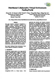
4. Collision detection and depth evaluation We chose to base our penetration depth computation neither on polyhedra nor polygons. Instead, we found convenient to use spheres to represent the volume of the bodies. Similarly to [12] and [11], we compute a scalar function for each object which characterizes the depth of a point inside the object. This field is then approximated by summing elementary depth maps generated by spheres (see Fig. 2). Since this construction is too slow to be performed at run time, it is only applied on unmovable or rigid bodies in the preparation phase. For each deformable model, an appropriate 2
And velocities, in specific cases.
construction method has to be found. If a volumetric body is decomposed into tetraedra for its mechanics, the collision model is obtained by surrounding each tetraedron with a sphere. For 2D body, we only sample the surface with a sufficient number of spheres (the sampling can be adaptive) (See Fig. 3.).
Fig. 2. A uterus modeled with 110 spheres
Fig. 3. Sampling of a tissue with about 500 spheres
During each simulation step, all the object spheres are put in a regular grid [29]: Only spheres in the same cell are checked for interpenetration. By checking spheres of the same body, this kind of CD can deal with self-collisions very easily. Several optimizations have been used such as time-stamping techniques to avoid emptying the grid or to prevent from generating the same colliding sphere couple twice. Moreover, the spheres of the unmovable bodies are put in the grid once for all, at the beginning of the simulation. Though not implemented yet, it would be convenient to use a hierarchical grid, to take into account various sphere radii.
Object A
Object B
Fig. 4. The colliding spheres and the generated forces between two objects
The previously seen method generates a list of colliding spheres. A collision between two bodies will generally induce several sphere overlaps. A local spring is then inserted between colliding spheres, which generates on their centers a force proportional to the interpenetration. Each body is submitted to the sum of all the forces acting on its spheres (see Fig. 4). This collision processing scheme has been adapted to
design an intermediate model for the control of haptic devices. More details can be found in [9].
5. Implementation 5.1.
Architecture of the system
The previous sections presented the fundamental ideas of our simulation testbed, called SPORE (Simulation of Physically-based Objects for Real-time Environments). It is implemented in C++ and operational on different platforms (Windows/Unix). In order to be as flexible as possible, SPORE relies on a minimal kernel in charge of all common processes, which include the integration of ODE, collisions and linking constraints (we use springs for such constraints). Apart from the kernel, a collection of physically-based models is proposed. Fig. 5 shows the software architecture. The bodies are grouped in three main categories: − Unmovable bodies: These objects cannot be moved, but can prevent objects from moving as they become obstacles. We can take benefit of this property in CD. − Active bodies: The position of these bodies are controlled by the user in a straightforward way. − Passive bodies: These objects are animated by the physical laws. They are called passive because they only undergo and react to external constraints and cannot move on their own.
The process of the kernel lies in the following simple loop: while (not_done) { forall active bodies get their position detect collisions forall colliding spheres compute collision response forall linking constraints compute their forces forall active bodies compute their force feedback forall passive objects sum their forces compute accelerations and velocities Integrate the state vector ODE Compute the new state vector of the system }
Kernel
Collection of autonomous physically-based models
Position sensors
Active Bodies
Unmovable Bodies
Force feedback devices
Integration Passive Bodies
Collisions
Constraints
Display
Fig. 5. Architecture of the SPORE environment
5.2.
Results
We have tested a number of mechanical bodies in our system, in the framework of a lapararoscopic surgical simulator for gynaecology. We currently simulate rigid bodies (see Plate 1), fluids as particles with Lennard-Jones interaction (see Plate 3), 2D mass/spring nets (see Plate 2), volumetric bodies with a deformable surface [21] (see Plate 4), dynamic splines [19] (see Plate 5). The computation time of a simulation loop is shown in Table 1: These times have been measured on a 1GHz Pentium III (see http://www.lifl.fr/~meseure/SPORE for videos). Table 1: Simulation times of various objects including CD with the tools and the environment. Rigid Body 1ms
Fluid 2ms
Mass/ spring 4ms
Deformable body 2ms
1D dyn. Spline 8ms
2D dyn. Spline 16ms
These times include the mechanical simulation and all the collisions of the scene (including tools and camera). The implicit integration scheme is always chosen except when it is useless (for fluids for instance). On Plate 6., we show the simulation of an intestine in the abdominal cavity. We also control laparoscopic forceps with force feedback.
6. Physical simulation vs special effects All the algorithms used in our library have been optimized to provide the most efficient simulation. However, the computation time tends to be prohibitive as the simulation becomes more complex. We have found convenient for some complex phenomena to use only visual effects instead of heavy physical simulations. For instance, we use textures to represent the coagulation steam, since the simulation and the visual representation of smoke is generally very time-consuming. For sucking up the blood and other liquids, we do not actually simulate the fluid flow, but instead we only discard some particles of the model. Other tools such as clamps are not physically simulated as well.
We are searching for some criteria allowing us to decide between a special effect and a physical simulation. For instance, if a phenomenon does not im-
ply behavioral alterations of the surrounding bodies, it can be only represented visually. However, if a realistic behavior is crucial, a physically-based approach is necessary.
7. Conclusion In this paper we have presented an environment which enables the simulation of various deformable bodies. It handles the mechanical behavior, the visualization and the interaction between bodies through a decomposition of models in three units. Our library provides a powerful tool to design surgical simulators. We are currently working on adding volumetric objects such as finite difference and/or finite element models. We are specially interested in multiresolution to trade-off between accuracy and computation time.
Acknowledgements This project has received a grant from ANVAR, the RNTL and the ACI 2001. The design of the intestine has been studied within a collaboration with the EVASION project of INRIA Rhône-Alpes which is supported by an ARC INRIA.
References 1. Baraff, D., and Witkin, A., “Large Steps in Cloth Simulation” Siggraph'98, Computer Graphics annual conference series, Orlando, 19-24 July 1998, 43-54. 2. Berkley, J., Weghorst, S., Gladstone, H., Raugi, G., Berg, D., and Ganter, M., “Banded Matrix Approach to Finite Element Modelling for Soft Tissue Simulation” Virtual Reality: Research, Development and Applications, 4, 203-212. 3. Bro-Nielsen, M., and Cotin, S., “Real-time Volumetric Deformable Models for Surgery Simulation using Finite Elements and Condensation” Eurographics’96, Computer Graphics Forum, 15 (3), Poitiers, 28-30 August 1996, 57-66. 4. Cani, M.P., “Layered Deformable Models with Implicit Surfaces” Graphics Interface’98, Vancouver, 18-20 June 1998, 201-208. 5. Chadwick, J.E., Hauman, D.R., and Parent R.E., “Layered Construction for Deformable Anima-ted Characters” SIGGRAPH’89, Computer Graphics, 23(3), Boston, 31 July- 4 August 1989, 243-252. 6. Cotin, S., Delingette, H., and Ayache, N., Real-Time Elastic Deformations of Soft Tissues for Surgery Simulation" IEEE Trans. on Visualization and Computer Graphics, 5 (1), January-March 1999, 62-73. 7. Cotin, S., Delingette, H., and Ayache, N., "A hybrid elastic model allowing real-time cutting, deformation and force-feedback for surgery training and simulation" The Visual Computer, 16 (8), 2000, 437-452. 8. Cover, A.S., Ezquerra, N.F., O’Brien, J., Rowe, R., Gadacz, T., and Palm, E., “Interactively Deformable Models for Surgery Simulation” IEEE Computer Graphics & Applications, 13 (6), November 1993, 68-75. 9. Davanne, J., Meseure, P., and Chaillou, C., “Stable Haptic Interaction in a Dynamic Virtual Environment” IEEE/RSJ IROS 2002, Lausanne, 1-3 October 2002.
10. Debunne, G., Desbrun, M., Cani, M.P., and Barr, A.H., “Dynamic Real-Time Deformations using Space & Time Adaptive Sampling” Siggraph’01, Computer Graphics annual conference series, Los Angeles, August 2001. 11. Eberhardt, B., Hahn, J., Klein, R., Strasser, W., and Weber, A., "Dynamic Implicit Surfaces for Fast Proximity Queries in Physically Based Modeling", Graphisch-Interaktive Systeme (WSI/GRIS), Universität Tübingen, 2000. 12. Fisher, S., and Lin, M.C., “Fast Penetration Depth Estimation for Elastic Bodies using Deformed Distance Fields” IEEE/RSJ IROS, 2001. 13. France, L., Lenoir, J., Meseure, P., and Chaillou, C., "Simulation of a Minimally Invasive Surgery of Intestines", VRIC 2002, Laval, 17-23 June 2002. 14. Hilde, L., Meseure, P., and Chaillou; C., "A fast implicit integration method for solving dynamic equations of movement" VRST'200, Banff, 15-17 November 2001, 71-76. 15. Hubbard, P.M., “Approximating Polyhedra with Spheres for Time-Critical Collision Detection” In ACM Trans. on Graphics, 15 (3), July 1996, p 179-209. 16. James, D.L., and Pai, D.K., "ARTDEFO: Accurate Real Time Deformable Objects" Siggraph'99, Computer Graphics annual conf. series, Los Angeles, 8-13 August 1999, 65-72. 17. Johnson, D.E., and Cohen, E., “Bound Coherence for Minimum Distance Computations” IEEE ICRA, Detroit, 10-15 Mai 1999, 1843-1848. 18. Kim, Y., Otaduy, M., Lin, M., and Manocha, D., “Fast Penetration Depth Computation for Physically-based Animation”, ACM Symp. on Computer Animation, 21-22 July 2002. 19. Lenoir, J., Meseure, P., Grisoni, L., and Chaillou, C., "Surgical Thread Simulation" MS4CMS, Rocquencourt, 12-15 November 2002. 20. Luciani, A., Habibi, A., Vapillon, A., et Duroc, Y., “A Physical Model of Turbulent Fluids” EUROGRAPHICS workshop on Animation and Simulation, Maastricht, 2-3 september 1995, 16-29. 21. Meseure, P., and Chaillou, C., "A Deformable Body Model for Surgical Simulation" Journal of Visualization and Computer Animation, 11 (4), September 2000, 197-208. 22. Moore, M., and Wilhelms, J., “Collision Detection and Response for Computer Animation” Siggraph’88, Computer Graphics, 22, 4, Atlanta, 1-5 August 1988, 289-298. 23. Nienhuys, H.W., and van der Stappen, A.F., "Combining Finite Element Deformation with Cutting for Surgery Simulations", Eurographics’00 (short presentations), Interlaken, 20-25 August 2000, 43-51. 24. Picinbono, G., Delingette, H., and Ayache, N., “Non-Linear and Anisotropic Elastic Soft Tissue Models for Medical Simulation” IEEE ICRA, Seoul, Korea, 2001. 25. Quinlan S., “Efficient Distance Computation between Non-Convex Objects” IEEE ICRA, 1994. 26. Rémion, Y., Nourrit, J.M., and Nocent, O., “Dynamic Animation of n-Dimensional Déformable Objects” WSCG’2000, Plzen, 7-11 February 2000. 27. Sagar M. A., Bullivant D., Mallinson G. D., Hunter P. J, and Hunter J. W., “A Virtual Environment and Model of the Eye for Surgical Simulation” Siggraph’94, Computer Graphics annual conf. series, Orlando, 24-29 July 1994, 205-212. 28. Triquet, F., Meseure, P., and Chaillou, C., “Fast Polygonization of Implicit Surfaces” WSCG’01 Conference, Plzen, 5-8 February 2001, 283-290. 29. Turk, G., Interactive Collision Detection for Molecular Graphics, Master Thesis, Technical Report TR90-014, University of North Carolina, 1989. 30. Van den Bergen G., “Proximity Queries and Penetration Depth Computation on 3D Game Objects” Game Developper Conference, 2001. 31. Wu, X., Downes, M., Goketin, T., and Tendick, F., “Adaptive Nonlinear Finite Elements for Deformable Body Simulation using Dynamic Progressive Meshes” Eurographics’01, Computer Graphics Forum, 20 (3), Manchester, 4-7 September 2001.
Plates
Plate 1: Simulation of a rigid ovary.
Plate 2: Simulation of a tissue.
Plate 3: Simulation of blood as a particle system.
Plate 4: Deformation of a surface body (an ovary).
Plate 5: Simulation of a piece of string modeled by a 1D dynamic spline.
Plate 6: Simulation of an intestine.
Plate 7: Coagulation steam.
Plate 8: Clamping of a fallopian tube.